Ceriatone Bluesbreaker JTM45 User manual

!
!
1
JTM45 “Bluesbreaker”
35W Amplifier
User’s Manual

!
!
2
Thank you for the purchase of your Ceriatone JTM45 Bluesbreaker guitar amplifier!
Here, we hope to explain how best to use your new amp.
Table of Contents
1) About the Bluesbreaker …...…………………………………………………………………………………………page 2
2) Quick setup……………………………………………………………………………………………………………page 3
3) Front Panel controls………………………………………………………………………………………………….page 4
4) Rear Panel controls…………………………………………………………………………………………………..page 7
5) Tube compliment and bias adjustment……………………………….……………………………………………page 9
6) Frequently Asked Questions………………………………………………………………………………………...page 13
7) Settings templates…………………………………………………………………………………………………….page 15
1) About the JTM45
Our British series of amplifiers has been overwhelmingly popular, and is still the backbone of our amplifier line. One of our
favorite circuits for all-around versatility is the JTM45.
This amplifier is based on the amp head that started the British sound, courtesy of a slightly modified Tweed Bassman circuit.
With a higher gain 12AX7 input tube, KT66 output tubes, and different transformers and component types gave the circuit new
life.This particular iteration is that used by Clapton, and was paramount in shaping the sound of rock and roll. It includes a
juicy bias-modulating tremolo that is footswitchable.
You’ll notice our version holds true sonically, but adds modern features including external bias measurement and adjustment,
an effects loop.
Most of all, we hope the Bluesbreaker becomes an integral part of your tone equation to exhilarate your playing and music.
Rock on!
-Nik Azam

!
!
3
2) QUICK SETUP (for instant gratification)
!
1) Plug your guitar using a 1/4” instrument cable into the upper I input on the right of the front panel
2) Plug a suitable power cable from the Plexi’s rear panel MAINS cable inlet to your wall power receptacle
3) Plug the Plexi into your speaker cabinet using 1/4” speaker cable
4) Set the IMPEDANCE SELECTOR to the match the impedance of your speaker cabinet
5) Plug a footswitch into the rear FOOTSWITCH 1/4” jack
6) Set all rotary tone and gain controls on the front panel to 12:00 (clock face)
7) Set VOLUME controls at just above minimum
8) Set front panel POWER switch in the ON position (down position, with adjacent STANDBY switch in the “STANDBY”
mode) for 30 seconds to allow tube filaments to warm up
9) Set front panel STANDBY switch to “ON” mode (down position)
10)ROCK!!!!!!

!
!
4
3) FRONT PANEL CONTROLS
From left to right:
1) POWER 2-way toggle switch
2) STANDBY 2-way toggle switch
3) INDICATOR LED
4) SPEED control
5) INTENSITY controll
6) PRESENCE control
7) BASS control
8) MIDDLE control
9) TREBLE control
10)VOLUME I control
11)VOLUME II control
12)INPUT I and II input ¼” instrument jack

!
!
5
POWER two-way toggle switch powers the JTM45 on and off. With the toggle switch in the DOWN (“ON”) position, the amp is
on. In the UP position, the amp is OFF.
STANDBY applies high voltage to the vacuum tube anodes (and screen grids) during use of the JTM45.To ensure long tube
life, first power the unit on with the STANDBY toggle switch in UP position for approximately 30 seconds. You can then switch
to DOWN (“ON”) to use the JTM45. With the toggle switch in the UP position, the JTM45 is in STANDBY mode. In the DOWN
position, the Plexi is in OPERATE mode
INDICATOR will illuminate when the Plexi is powered by turning the front panel POWER toggle switch to the ON position. If
INDICATOR does not turn on, check your power cable connections, and then the fuse on the rear of the unit.
SPEED adjusts the speed of the tremolo effect. Turning it clockwise increases how quickly the volume pulses.
INTENSITY adjusts how dramatic the volume sweep of the tremolo effect is. Turning it clockwise increases the difference
between the “quiet” and “loud” phases of the volume pulses.
PRESENCE adjusts the high frequency response of the power amplifier using negative feedback. Use this control to add
sparkle and clarity to your tone.
BASS adjusts low frequencies
MIDRANGE adjusts the mid frequency response
TREBLE adjusts the high frequency response
VOLUME I sets the overall volume and gain of the “BRIGHT” channel of the JTM45.
VOLUME II adjusts the overall volume and gain of the “NORMAL” channel of the JTM45

!
!
6
INPUT I and II are ¼” jacks for instrument cables. Plug your guitar in here. Use the I input for the BRIGHT channel. The
BRIGHT channel has more gain, more treble, and a more prototypical JTM45 tone. The UPPER I input is higher gain, whereas
the LOWER I input is lower gain. Use the II input for the NORMAL channel. The NORMAL channel is much darker, lower gain,
and has an abundance of lower frequencies. The UPPER II input is higher gain, whereas the LOWER II input is lower gain.

!
!
7
4) REAR PANEL CONTROLS
From left to right:
1) SEND ¼” instrument jack
2) RETURN ¼” instrument jack
3) IMPEDANCE SELECTOR three-way rotary selector
4) SPEAKERS ¼” speaker jacks (x2)
5) BIAS TEST probe jacks (x2)
6) COM probe jack
7) FULL / HALF 2-way toggle switch
8) TREMOLO FOOTSWITCH ¼” jack
9) HT FUSE
10)MAINS FUSE
11)MAINS IEC cable inlet
SEND ¼” instrument jack can be used to directly interface the preamps of the JTM45, thereby bypassing the power amplifier.
Conversely, this is usually used as the SEND of the effects loop. Plug the input of your effects unit, or interface device (ex – C-
lator, Klein-ulator) into this jack using ¼” instrument cable.
RETURN ¼” instrument jack can be used to directly interface the power amp of the JTM45, thereby bypassing the preamp and
using the amplifier as a power amplifier. Conversely, this is usually used as the RETURN of the effects loop. Plug the output of
your effects unit, or interface device (ex – C-lator, Klein-ulator) into this jack using ¼” instrument cable.

!
!
8
IMPEDANCE SELECTOR three-way rotary selector. Set to the position that matches the impedance of your speaker cabinet.
NOTE – if you are using two speaker cabinets in parallel (ex – two 16 Ohm cabinets), set the impedance selector to half that of
a single cabinet (in this case, 8 Ohms).
SPEAKERS ¼” speaker cable jacks. Use a ¼” speaker cable to connect your speaker cabinet to the amplifier using these
jacks. If you use one speaker cabinet, either jack is acceptable.
NOTE – never turn your amplifier to OPERATE mode (“1” / DOWN position on STANDBY) without connecting the amplifier to a
speaker cabinet or suitable dummy load! Failing to do so may damage your amplifier!
BIAS TEST and COM multimeter probe jacks – use this for external bias current measurements (see Section 5, Page 9)
FULL / HALF switches the power output of the power amp. For the JTM45, half mode is approximately 18W. HALF mode
configures the power tubes to run in triode operation, and this negates any need to reconfigure the IMPEDANCE SELECTOR.
TREMOLO FOOTSWITCH ¼” jack. Plug in the cable for the footswitch. The footswitch will turn the tremolo on and off.
HT FUSE T500mA fuse – used to protect your amplifier from voltage spikes or excessive current draw. Replace only when
necessary.
MAINS FUSE slow-blow fuse – used to protect your amplifier from voltage spikes or excessive current draw. Replace only
when necessary. 3A is used for amplifiers used with a 120VAC country supply, and 2A is used with 240VAC.
MAINS IEC cable inlet – plug a suitable IEC power cable into this inlet to power your amplifier

!
!
9
5) TUBE COMPLIMENT AND BIAS ADJUSTMENT
From left to right:
V1 – 12AX7/ECC83 (Input stage Bright and Normal channels)
V2 – 12AX7/ECC83 (stage 2 and tonestack cathode follower)
V3 – 12AX7/ECC83 (phase inverter for power amplifier)
V4 – KT66
V5 – KT66
V0 – 12AX7/ECC83 (driver for tremolo circuit)
V6 – GZ34/5AR4
BIAS ADJUSTMENT CONTROL IS INDICATED BY THE RED ARROW

!
!
10
To measure your power tube bias, carefully follow these steps with the amplifier in OPERATE, MASTER at minimum, and
connected to a speaker load (not doing so may damage your amplifier!):
1) Turn on a digital multimeter (DMM), and set it to read millivolts (mV) in the 100mV range (this will vary from DMM to
DMM)
2) Plug a black probe into the color-coded jack on your DMM, and do the same for a red probe
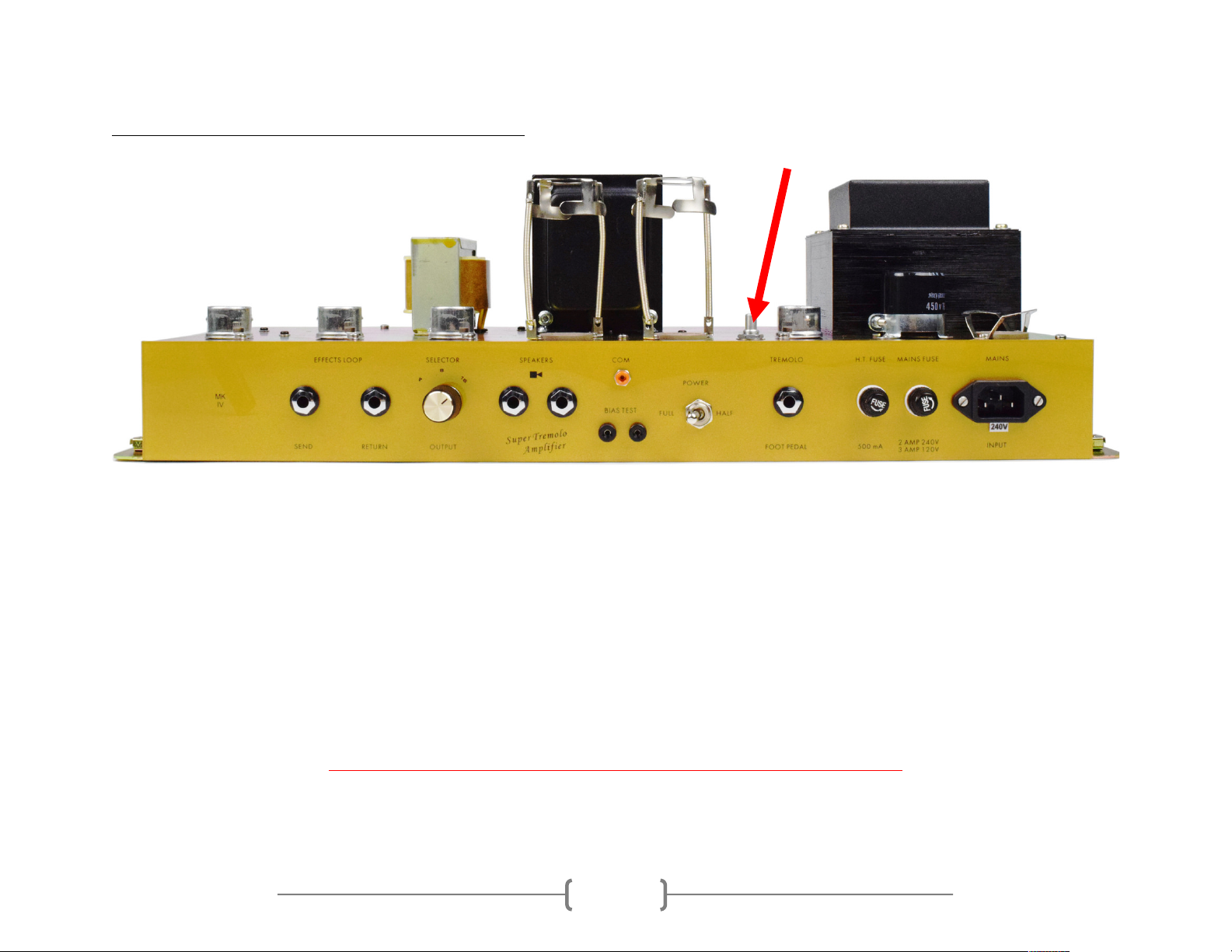
3) Plug the black probe tip into the COM multimeter jack on the rear of the amp
4) Plug the red probe tip into the LEFT BIAS multimeter jack on the rear of the amp. This measures bias for the KT66
closest to V3. Right down the value your DMM reads. You might expect a value between 30mV-40mV.
5) Repeat for the other power tube position by plugging your red probe into the RIGHT BIAS multimeter jack.
Okay, now I’ve measured my bias. Now what?
To calculate bias, there are two pieces of information you need to know: your amplifier’s power tube plate voltage, and the
published value for maximum plate dissipation for the power tubes used in your amplifier. To save you some time and energy,
here are those two values:
-Approximate plate voltage for JTM45 amplifiers = 420VDC
-Maximum plate dissipation for KT66s = 25W
…and now some math. The formula for calculating bias is as follows:
𝑚𝑎𝑥𝑖𝑚𝑢𝑚 𝑝𝑙𝑎𝑡𝑒 𝑑𝑖𝑠𝑠𝑖𝑝𝑎𝑡𝑖𝑜𝑛
𝑎𝑚𝑝𝑙𝑖𝑓𝑖𝑒𝑟 𝑝𝑙𝑎𝑡𝑒 𝑣𝑜𝑙𝑡𝑎𝑔𝑒 × 𝑝𝑒𝑟𝑐𝑒𝑛𝑡 𝑜𝑓 𝑚𝑎𝑥𝑖𝑚𝑢𝑚 𝑑𝑖𝑠𝑠𝑖𝑝𝑎𝑡𝑖𝑜𝑛 × 1000 =𝑏𝑖𝑎𝑠 𝑐𝑢𝑟𝑟𝑒𝑛𝑡 (𝑚𝐴)
In most cases, amplifiers are biased between 50% and 75% dissipation. We bias the JTM45 to 35mV reading on a DMM.

!
!
11
An example is as follows:
25𝑊
420𝑉𝐷𝐶 × 60% × 1000 =𝑎𝑏𝑜𝑢𝑡 35𝑚𝐴
You might wonder why your DMM is set to millivolts and not milliamps – simply, we have a 1 Ohm resistor placed between your
probe jacks and ground to convert a current reading to a voltage reading. That way, a bias current of 35mA measures as 35mV
on your DMM.
NOTE – Only set your DMM to mV for measuring bias on the amplifier. Not doing so may damage your DMM.
Now that you know how to calculate bias, all you need to do is:
1) Follow steps 1-5 on page 11
2) Calculate what bias voltage reading you will set your tubes to (in this case, we will use 35mV)
3) Place your red probe in the LEFT BIAS jack, and the black probe in the COM jack.
4) Turn the bias potentiometer shaft SLOWLY until your DMM reads 35mV
5) Wait 1 minute
6) Recheck all power tube bias measurements
7) Readjust bias potentiometer shaft if necessary

!
!
12
A FEW COMMENTS ON BIASING
Due to the nature of vacuum tube amplification, there are inherent risks when biasing your amplifier. Extremely high-voltages
are present, and vacuum tubes reach high temperatures during use.
The risk of electrical shock and/or skin burns should ALWAYS be kept in mind. Therefore, bias at your own risk, and only while
paying attention and taking all precautionary measures.
Biasing should only be done on a clean workbench with no distractions. Do not wear loose clothing or any jewelry. Take your
time, and think carefully before each step.
Again, bias at your own risk. Ceriatone Amplification is not responsible for any damages or injuries resulting from user biasing.

!
!
13
6) FREQUENTLY ASKED QUESTIONS
How do I hook up this thing?
-See Section 2, beginning on page 3.
Is the FX loop series or parallel? Active or passive?
-The FX loop is series, and is currently passive. However, we have plans to release an option for a tonally
transparent solid-state FX loop. Stay tuned!
When I plug effects into the effects loop, my tone noticeably changes. Sometimes the effects don’t sound quite right. What’s
the deal?
-Generally, what you’re hearing is a significant mismatching of impedances, and/or an overloading of the effect
unit itself. Most rack-mount units have different input impedance than pedals, and thus can sometimes
function fine without a buffer before them. In addition, some of these rack-mounted effects can pad the
volume they receive, preventing it from overloading. Pedals do not have proper input impedance or padding
ability, and therefore do not play nicely.
-For best results, an effects loop interface like the C-lator or Klein-ulator should be used. These units prevent
impedance mismatching, as well as provide the ability to pad down the volume sent to the effects units hence
preventing any overloading.

!
!
14
Can I substitute different tube types?
-Although you can try 12AT7s, 12AU7s, 5751s without any harm, the design is optimized for 12AX7s, and are
therefore the only recommended tube in the preamp positions. 5881 tubes are a suitable replacement, but
we prefer KT66s for this amplifier. Use only a GZ34/5AR4 rectifier tube.
Do I need to use a matched and balanced phase inverter?
-It is not necessary. Feel free to experiment with different tubes (of the same type) in your amp, though!
I’ve read that the components used in this type of amplifier are really important. What is inside my amplifier?
-We use a combination of parts custom-made for us to our specifications (power transformer, output
transformer, choke, high-temperature / low-ESR electrolytic capacitors) and those used in our British series
(1/2W carbon composition resistors, 1W carbon film resistors, TAD Mustard capacitors, high-voltage silver
mica capacitors, Belton tube sockets, and Alpha potentiometers, Cliff jacks). Finally, we occasionally use
NOS components from our vast surplus parts collection in locations they work well and complement the
voicing or enhance the performance of the amplifier.
I like to use rack-mounted multieffects units. What is the output level straight from the EFFECTS LOOP SEND jack, -10dB or
+4dB?
-While not exact, -10dB is a better approximation than +4dB. The actual output level will depend on your
settings, particularly the volume controls. +4dB is usually reserved for recording/P.A. equipment with
balanced connections.

!
!
15
7) Settings templates

!
!
16
Table of contents
Other Ceriatone Amplifier manuals

Ceriatone
Ceriatone JTM50 User manual

Ceriatone
Ceriatone Chupacabra HRP Series User manual

Ceriatone
Ceriatone Ceriatone User manual

Ceriatone
Ceriatone AFD 35 User manual

Ceriatone
Ceriatone Dizzy 30 User manual

Ceriatone
Ceriatone 2550 User manual

Ceriatone
Ceriatone AH Deluxe 50 User manual

Ceriatone
Ceriatone TMB User manual