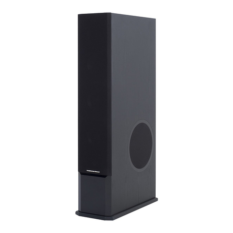
Advanced Visual Solutions CPS03 User manual

Advanced Visual Solutions Ltd
Unit 2, Eastman Way
Hemel Hempstead, Hertfordshire HP2 7DU
Telephone : ( 01442 ) 252280 Fax : ( 01442 ) 244578
DOCUMENT NUMBER AVS/CPS03/OEM/01 REV 4.0 11th October 2007
Model :-
CPS03 & CPS03A
6 Watt Public Address
Powered Loudspeaker
Ceiling Tile Mount
Installation and Operating
Instructions

CPS03 & CPS03A POWERED LOUDSPEAKER
The CPS03 series is designed to mount directly into a 209mm circular aperture in a ceiling tile or dry
wall, and will operate directly from the ADPRO Colour and Audio transmission systems.
It is supplied complete with an aluminium fire-check dome which must be installed with the unit.
The unit is designed to operate from any regulated power supply which provides 12 Volts DC @
1000mA.
The unit incorporates an audio pre-amplifier and an audio power amplifier giving a maximum output of
6 Watts RMS at 12 Volts DC. The pre-amplifier and power amplifier are in a single integrated device
and may be used with audio signals ranging from 50mVpp to 5000mVpp, with a source impedance of
up to 10k Ohms.
An internal sensitivity jumper selects high or low sensitivity (see specifications for details).
The balanced units (“A” suffix) may be used with balanced line equipment and incorporates a
balancing transformer.
When used in unbalanced mode, the screen of the input cable should be earthed (this is normally
connected to earth by the source equipment). See example connection drawings later in this
document.
CABLING
We strongly recommend that all audio signal cables should be a good quality type, with overall
screen. Failure to use the correct cable type may result in noisy or unusable audio performance.
PLEASE SEE INSTALLATION DRAWINGS LATER IN THIS DOCUMENT.
AUXILIARY POWER and “THROUGH” CONNECTIONS
If the unit is to be used as a “separate loudspeaker plus microphone” intercom system, a facility exists
to provide the microphone unit (AVS product code AVSM2 or AVSM3) with the required 12 Volts DC
from the speaker unit. The audio from the microphone can be routed through the speaker unit,
allowing audio both to and from the ADPRO transmitter to be carried in a single cable (a screened,
twin, twisted pair). This makes cabling simpler as all cables to/from the microphone only go to the
speaker unit (see sample drawings later in this document).
NOTE: The 12 Volt DC supply output from the speaker unit is current-limited and has independent
reservoir and filter capacitors. It intended to supply one AVSM2 microphone only.
DO NOT ATTEMPT TO USE THIS OUTPUT FOR ANY OTHER PURPOSE!
DOCUMENT NUMBER AVS/CPS03/OEM/01 REV 4.0 11th October 2007 Page 2 of 12

INSTALLATION
The kit includes :-
The Loudspeaker, quick-fit housing, fire-dome and audio amplifier module.
A regulated, 230VAC to 12 Volt DC, in-line power supply (1000mA)
A 15 pin “D” type socket (solder-bucket type)
A 15 pin “D” type metalised hood
Installation instructions and drawings
UNBALANCED SOURCE INSTALLATION ( e.g. Adpro fast-scan, FastVu or FastTrace )
The audio cable may be a simple microphone type e.g. RS Stock-Code 181-900.
IMPORTANT NOTE! The screen or drain-wire must be earthed at the SOURCE EQUIPMENT end
and MUST be connected to the connector marked “SCREEN” in the CPS03 unit when using single-
ended configuration. The power supply unit supplied has a floating 0 Volt line and should only be
replaced with a similar type.
The 12 Volt DC power should be supplied via a separate cable to the audio cable and needs only to
be a twin core, low-Voltage type. This cable does not require a screen and should ideally be of a
1.0mm2cross-section.
NOTE:- The 12 Volt DC power cable should be kept as short as possible and, in any event, no
longer than 10 metres.
BALANCED-LINE INSTALLATIONS (FOR CPS03A VERSION)
The system may be installed with source equipment which provides a balanced-line output. These
sources are normally low-impedance (e.g. 600 Ohm). A balancing/matching transformer is fitted in
models with an “A” suffix.
The audio cable should be of a twisted-pair type with overall screen e.g. RS Stock-code 365-8775
The audio signals may be switched using the AVS BINREL02 switcher. This unit incorporates audio
transformers which convert the un-balanced signals to and from the ADPRO equipment to true
balanced-line signals. If using a BINREL02 switcher, please see the installation drawings later in this
document.
IMPORTANT NOTE! The screen or drain-wire must be earthed at the SOURCE EQUIPMENT end
and should be connected at the CPS03A unit when using Balanced-Line configuration. The power
supply unit provided has a floating 0 Volt line and should only be replaced with a similar type.
The 12 Volt DC power should be supplied via a separate cable to the audio cable and needs only to
be a twin core, low-Voltage type. This cable does not require a screen and should ideally be of a
1.0mm2cross-section.
NOTE:- The 12 Volt DC power cable should be kept as short as possible and, in any event, no
longer than 10 metres.
DOCUMENT NUMBER AVS/CPS03/OEM/01 REV 4.0 11th October 2007 Page 3 of 12

TYPICAL INSTALLATION WIRING DIAGRAMS
CONNECTION DETAILS
CONNECTION POINT FUNCTION
AUDIO IN (H) AUDIO SIGNAL INPUT (HOT)
AUDIO IN (C) AUDIO SIGNAL INPUT (COLD)
SCREEN COMMON (0V) ( FOR CABLE SCREEN OR DRAIN )
OUT (H) THROUGH CONNECTION FROM IN (H) (from AVSM2 Microphone)
OUT (C) THROUGH CONNECTION FROM IN (C) (from AVSM2 Microphone)
+V OUT CURRENT LIMITED +12 VDC OUTPUT (for avsm2 microphone)
0V OUT COMMON (0V)
SCREEN COMMON (0V)
IN (H) AUXILIARY THROUGH (HOT) IN (From AVSM2 Microphone)
IN (C) AUXILIARY THROUGH (COLD)IN (From AVSM2 Microphone)
+VIN 12V DC POSITIVE SUPPLY INPUT
0V 12V DC 0V SUPPLY INPUT
LSP+ TO LOUDSPEAKER (HOT)
LSP- TO LOUDSPEAKER (COLD)
DOCUMENT NUMBER AVS/CPS03/OEM/01 REV 4.0 11th October 2007 Page 4 of 12

BASIC CONNECTION DETAILS : CPS03A POWERED LOUDSPEAKER PCB
Connection to an UNBALANCED Source
REMEMBER TO LINK THE SCREEN TERMINAL OF THE AMPLIFIER MODULE TO
THE INPUT(C) TERMINAL FOR UNBALANCED USE.
DOCUMENT NUMBER AVS/CPS03/OEM/01 REV 4.0 11th October 2007 Page 5 of 12

BASIC CONNECTION DETAILS : CPS03A POWERED LOUDSPEAKER PCB
Connection to a BALANCED Source
REMEMBER TO USE A SCREENED, TWISTED PAIR, OR A SCREENED 2-CORE
MICROPHONE CABLE FOR BALANCED USE.
DOCUMENT NUMBER AVS/CPS03/OEM/01 REV 4.0 11th October 2007 Page 6 of 12

BASIC CONNECTION DETAILS : CPS03A POWERED LOUDSPEAKER PCB
DIRECT CONNECTION TO ADPRO REMOTE A/V TRANSMITTER
REMEMBER TO LINK THE SCREEN TERMINAL OF THE AMPLIFIER MODULE TO
THE INPUT (C) TERMINAL FOR UNBALANCED USE.
DOCUMENT NUMBER AVS/CPS03/OEM/01 REV 4.0 11th October 2007 Page 7 of 12

POWERED LOUDSPEAKER AND AVS MICROPHONE COMBINATION
DIRECT CONNECTION TO ADPRO REMOTE A/V TRANSMITTER
DOCUMENT NUMBER AVS/CPS03/OEM/01 REV 4.0 11th October 2007 Page 8 of 12

POWERED LOUDSPEAKER AND AVS MICROPHONE COMBINATION
CONNECTION TO ADPRO TRANSMITTER VIA AVS BINREL02
SEE DIAGRAM ON FOLLOWING PAGE FOR DETAIL OF ADPRO CONNECTION TO BINREL02
DOCUMENT NUMBER AVS/CPS03/OEM/01 REV 4.0 11th October 2007 Page 9 of 12

POWERED LOUDSPEAKER AND AVS MICROPHONE COMBINATION
CONNECTION TO ADPRO TRANSMITTER VIA AVS BINREL02
ALL INPUT & OUTPUT CABLES TO BE SCREENED TWISTED-PAIR TYPES
DOCUMENT NUMBER AVS/CPS03/OEM/01 REV 4.0 11th October 2007 Page 10 of 12

SPECIFICATIONS
The electrical specifications for all units are the same and are as follows:-
All figures based on supply Voltage = 13.8 VDC : Audio frequency = 1000 Hz.
PARAMETER CONDITIONS MIN TYP MAX UNIT
Supply Voltage Range 6.00 13.80 17.00 VDC
Current Consumption 40.00 ------- 1200.00 mA
Input Impedance 300.00 1K 10K Ohms
Input Sensitivity High Setting 50.00 200.00 500.00 mV pp
Input Sensitivity Low Setting 500.00 1000.00 5000.00 mV pp
Output Power <0.5% THD 5.00 6.00 8.00 Watts RMS
THD @ 1 Watt RMS ------- ------- 0.1 %
Amp. Power Bandwidth THD=0.5% PO=5W 50.00 ------- 15000.00 Hz
Supply Ripple Rejection @100Hz ------- 34.00 ------- dB
Output Noise Voltage Source=10K ------- 350.00 700.00 uV
Operating Temperature Complete Unit 3.00 20.00 60.00 oC
Input Configuration, Standard :-
Unbalanced line (Single-Ended).
The screen and “INPUT C” terminals are connected to Power adapter 0 Volt.
Input Configuration, “A” suffix :-
Balanced line.
Screen terminals are connected to Power Adapter 0 Volt.
DIMENSIONS
Diameter 230mm
Depth (including firecheck dome) 95mm
Cut-out (aperture) Diameter 209mm
FEATURES
Optimised for connection to ADPRO Fast-Scan, FastVu, FastTrace and FastTx transmitters
Low-Voltage DC BTL amplifier
Good Power Supply Ripple Rejection
Thermally Protected Audio Power Output Device
Reverse Polarity Protected
Thermal (Self-Resetting) Internal Fuse
Anti-Thump Circuitry.....( No Switch on/off "Plop" )
Semiconductors ESD Protected
Balanced line input by quality audio transformer (“A” suffix models)
Switchable Input Sensitivity ( Low/High Jumper )
On-Board Volume Control
Easi-Fit Clips ( Ceiling mount version only )
DOCUMENT NUMBER AVS/CPS03/OEM/01 REV 4.0 11th October 2007 Page 11 of 12

GENERAL ADVICE FOR AUDIO INSTALLATIONS
NEVER Make a joint in an audio cable. If this is necessary, use a good quality, screened connector
such as an XLR type.
NEVER Run audio signal cables in close proximity to mains, telephone, data or 100V line cables. If you
need to cross such cables, run the audio cable across at 90o.
NEVER Exceed the amplifier’s output rating.
For 100 Volt line use, calculate the output power demand by adding together all the
loudspeakers’ power tapping figures
For Example, an installation has the following loudspeakers:-
2 speakers @ 4 Watts
1 speaker @ 15 Watts
3 speakers @ 6 Watts
1 speaker @ 30 Watts
TOTAL DEMAND =
2 X 4 watts = 8 Watts
1 X 15 watts = 15 Watts
3 X 6 watts = 18 Watts
1 X 30 watts = 30 Watts
Therefore demand is 8 + 15 + 18 + 30 = 71 Watts
It is wise to allow at least a 10% overhead on amplifier power output ratings so, in the above
example, the amplifier should have a minimum rating of at least 80 Watts RMS
NEVER Mix 100V line and low impedance loudspeakers on the same amplifier.
NEVER Run 100V line loudspeaker cables in close proximity to ANY low voltage cables e.g. Data
cables, Telecom Cables, Low Voltage DC Supply Cables etc.
NEVER Use low impedance loudspeakers on 100V Line amplifiers.
NEVER Use low impedance loudspeakers where more than two loudspeakers are required, or where
loudspeakers are required to be installed more than a few metres away from the amplifier.
NEVER Use re-entrant horn loudspeakers for low frequency or music use, unless the unit has been
manufactured specifically for this purpose.
ALWAYS Use good quality audio cable for low-level signals such as microphones etc.
ALWAYS Use low impedance or Balanced Line transmission where low-level signals are to be
transmitted over distances in excess of a few metres. Audio signal transformers may be
required for impedance matching or to convert single-ended signals to balanced line.
ALWAYS Use a mains rated, double insulated cable for 100V Line loudspeakers.
ALWAYS Ensure that there no short-circuits on loudspeaker cables before connecting to the amplifier. An
amplifier running into a short circuit won’t last long!
ALWAYS Ensure that loudspeakers are in-phase (i.e. observe polarity) for maximum efficiency.
DOCUMENT NUMBER AVS/CPS03/OEM/01 REV 4.0 11th October 2007 Page 12 of 12
This manual suits for next models
1
Table of contents
Other Advanced Visual Solutions Speakers manuals
