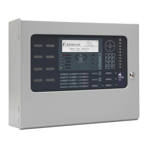
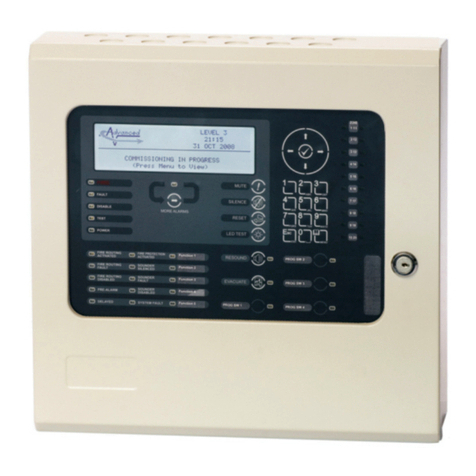
Advanced MxPro4 Series User manual

Installation Sheet &
Quick Reference Guide
www.advancedco.com
683-4000 REV 01
Controls & Indications
!!
E
V
A
C
U
A
T
E
S
I
L
E
N
C
E
/
R
E
S
O
U
N
D
R
E
S
E
T
M
U
T
E
P
Q
R
S
W
X
Y
Z
T
U
V
G
H
I
J
K
L
M
N
O
D
E
F
A
B
C
T
E
S
T
D
I
S
A
B
L
E
F
A
U
L
T
S
Y
S
T
E
M
F
A
U
L
T
S
O
U
N
D
E
R
D
I
S
A
B
L
E
D
S
O
U
N
D
E
R
S
I
L
E
N
C
E
D
S
O
U
N
D
E
R
F
A
U
L
T
P
O
W
E
R
D
E
L
A
Y
E
D
F
I
R
E
Navigation Buttons
Press to scroll through Menu Options.
Press to display more information.
Press to scroll through menu Options.
Press to scroll through lists of zones or devices.
Press to confirm entry of numeric or letter information
entry.
Press to confirm selection of a menu option.
Press to change some of the configuration options.
Number Buttons
to
9wxyz
0
Used to enter numbers or letters.
Esc
Press to return to a previous menu.
Press to exit the menu functions and return to the
normal display.
The panels may be fitted with separate zone fire indicators comprising of
20, 50, 100 or 200 red indicators –these show the zones in a fire alarm
condition.
In addition, the panels may be fitted with separate indications showing the
loaction of fire alarms in a pictorial display (mimic diagram).
Menu
Press to show or return to Level 1 or Level 2 Menu
Functions.
Main User functions are VIEW, TEST, DISABLE &
ENABLE.
Graphic Display
Control Buttons
The graphical display provides detailed information of the source of fires,
faults and warnings. It also shows menus for use when inspecting or
programming the operation of the panel.
Under normal conditions the panel display shows the time, date and
status: -
Reset: Press to reset the panel from a latched
condition.
Mute: Press to mute the internal buzzer.
LEVEL 2
16:05
04 MAR 2006
Silence / Re-sound: Press to silence the bells. Press
again to re-sound the bells.
Evacuate: Press to initiate a manual evacuation and
sound the alarms.
NORMAL PANEL OPERATION
(Press Menu to View)
Level 2 Access is required for Reset, Silence / Re-sound &
Evacuate buttons and for programming Menu functions. Level 2
operation can be enabled using a key-switch (if fitted) or by entry
of a pass-code.
The following is a typical menu display.
LED Status Indicators
[Level 2 Menu]
VIEW DISABLE ENABLE
TEST PRINT COMMISSION
STATUS
RED
Separate LED Indicators show the presence of a fire
alarm condition and (if configured) that the fire brigade
has been called.
YELLOW
Indicate other system operating conditions including
Fault, Test and Disablement conditions.
GREEN
Indicates the presence of power to the system –if
flashing, indicates that the panel is running on battery
standby power.
In the event of a fire alarm, call: -
For Service & Maintenance, contact: -
TEL:
TEL:
Graphic Liquid
Crystal Display
Navigation
Buttons
LED Status
Indicators
Control
Buttons
Number and
Letter Buttons
For full installation & commissioning information see document 680-014
For full operating instructions see document 680-015
www.advancedco.com/advanced-360-portal/premium-documents.aspx

MX-4100
MX-4010 / MX-4020
340
135
135
23
274
315
365
45
140
140
277
340
EARTH
LIVE
NEUTRAL
230V AC 50Hz 0.4A
POWER SUPPLY
OPTION (4100/L Only):
MXP-007 2-WAY RELAY CARD
See document 680-028
and/or
MXP-014 8-WAY INPUT CARD
See document 680-031
4100 320 x 345 x 88 mm
4100S 320 x 345 x 88 mm
4100/L 340 x 368 x 125 mm
ENCLOSURE: Steel IP30 RAL7035
DIMENSIONS:
ENCLOSURE: Steel IP30 RAL7035
DIMENSIONS:218 x 300 x 44 mm
113
113
296
213
23
173
INPUT
SCR
B
A
PSE EN54-4,
24V [15V-30V] DC 0.2A
OUTPUT 1
To Next Unit
POWER SUPPLY
PSE
FAULT
SCR
B
A
NETWORK
MX-4010, MX-4020 Standard Network
MX-4010/FT, MX-4020/FT Fault Tolerant Network
OUTPUT
For more information see document
680-029

Loop
Sounder Outputs
Relay 30V, 1A
1
Fault
2
Fire
24V DC 1.4A Load
4100 : 7Ah
4100/L : 12Ah
BATTERY
24V DC 0.5A
24V DC 1.0A
AUX Output
24V DC 0.5A
EOL
EOL
From Transformer
OPTION:
MXP-024 LED Card
Mounts behind chassis
(Requires alternate
fascia label) –see
document 680-036
INPUT
SCR
B
A
SCR
B
A
OUTPUT
NETWORK
OPTION: MXP-003 / MXP-009
Mounts behind chassis –see
document 680-027
Not available on MX-4100S
!!
EVACUATE
SILENCE/
RESOUND
RESET
MUTE
ESC MENU
PQRS WXYZTUV
GHI JKL MNO
DEFABC
TEST
DISABLE
FAULT
SYSTEMFAULT
SOUNDER
DISABLED
SOUNDER
SILENCED
SOUNDER
FAULT
POWER DELAYED
FIRE
EN 54-2
EN 54-4
BATTERIES:
38Ah max
!!
EVACUATE
SILENCE/
RESOUND
RESET
MUTE
ESC MENU
PQRS WXYZTUV
GHI JKL MNO
DEFABC
TEST
DISABLE
FAULT
SYSTEMFAULT
SOUNDER
DISABLED
SOUNDER
SILENCED
SOUNDER
FAULT
POWER DELAYED
FIRE
EN 54-2
EN 54-4
!!
EVACUATE
SILENCE/
RESOUND
RESET
MUTE
ESC MENU
PQRS WXYZTUV
GHI JKL MNO
DEFABC
TEST
DISABLE
FAULT
SYSTEMFAULT
SOUNDER
DISABLED
SOUNDER
SILENCED
SOUNDER
FAULT
POWER DELAYED
FIRE
EN 54-2
EN 54-4
LOOPS:
CHASSIS 1: 1-4
CHASSIS 2: 5-8
BATTERIES:
CHASSIS 1
CHASSIS 2
38Ah max
4200LE / 4400LE
4800
481
266
!!
EVACUATE
SILENCE/
RESOUND
RESET
MUTE
ESC MENU
PQRS WXYZTUV
GHI JKL MNO
DEFABC
TEST
DISABLE
FAULT
SYSTEM FAULT
SOUNDER
DISABLED
SOUNDER
SILENCED
SOUNDER
FAULT
POWER DELAYED
FIRE
EN 54-2
EN 54-4
4200R 266 (6U) x 481 (19”) x 100 mm
4400R 266 (6U) x 481 (19”) x 100 mm
NOTES:
IP30 rating is for the MX4000R
module only with the door
closed and with module
mounted in a standard rack
mount enclosure –assumes all
other rack mount positions are
occupied –no overall rating is
implied

MX-4200/4400/4800
OPTION:
MXP-013 LED Cards
Mounts on back of
panel door
(Requires alternate
door) –see document
680-036
OPTION:
MXP-007/008 2/8-WAY RELAY CARD
See document 680-028 and/or
MXP-014 8-WAY INPUT CARD
See document 680-031
Or other PBUS Module
See document supplied with the
module
Loops
Sounder Outputs
24V DC 2.6A Load
4200,4400 : 18Ah max
4200/D, 4400/D : 38Ah max
24V DC 0.5A
BATTERY
24V DC 1.0A
Sounder C&D are
not fitted on 4200
AUX Output
24V DC 0.5A
INPUT
SCR
B
A
OUTPUT
NETWORK
OPTION: MXP-003 / MXP-009
Mounts on chassis –see
document 680-027
EARTH
LIVE
NEUTRAL
POWER SUPPLY
220-240V AC 50Hz 1.0A
Relay 30V, 1A
2
Fire
1
OPTION: MXS-040
Battery Temp. Sensor
Supplied as standard on
4200LE, 4400LE and 4800.
This must be fitted to ensure
correct charging voltage.
EOL
EOL
EOL
EOL
PBUS
RS485
OPTION: MXP-031 PBUS I/F
Fits into socket on PCB
Required for connection of PBUS
modules –see document 680-083
for more information.
EVACUATE
SILENCE/
RESOUND
RESET
MUTE
670-1027-04c
ESC MENU
PQRS WXYZTUV
GHI JKL MNO
DEFABC
TEST
DISABLE
FAULT
SYSTEM FAULT
SOUNDER
DISABLED
SOUNDER
SILENCED
SOUNDER
FAULT
POWER DELAYED16 17 18 19 20
11 12 13 14 15
6 7 8 9 10
1 2 3 4 5
ZONE
EN 54-2
EN 54-4
!
FIRE
OPTION:
MXP-025 LED Card
Mounts on fascia plate
(Requires alternate
fascia label) –see
document 680-036
DISPLAY FASCIA PLATE IS NOT
SHOWN FOR CLARITY
LOOP DRIVER CARDS:
MXP-002: Apollo / Hochiki
MXP-069: Advanced AV
MXP-067: Nittan
All loop drivers must be of the same
type. Requires specific panel firmware
for protocol.
Loops 3&4 are not fitted on 4200
LOOP 1
A
B
SCR
LOOP 2
LOOP 3
LOOP 4
4200 & 4400 475 x 450 x 125 mm
4200/D & 4400/D 475 x 450 x 190 mm
ENCLOSURE: Steel IP30 RAL7035
DIMENSIONS:
450
190
190
45
410
475
450
190
190
45
370
950
885
4200LE 950 x 450 x 190 mm
4400LE
4800
Ratings are per
chassis!
Other manuals for MxPro4 Series
4
Other Advanced Fire Alarm manuals
Popular Fire Alarm manuals by other brands
SILENT KNIGHT
SILENT KNIGHT INTELLIKNIGHT 5820XL installation manual

ESP
ESP MAGPRO-WSS23 Installation instruction
Autronica
Autronica AutroSafe BS-3 manual
Mircom
Mircom FleX-Net FX-4000 user guide
SILENT KNIGHT
SILENT KNIGHT 5860 Installation quick reference

Honeywell
Honeywell HW-TG7FS-V Installation and operating guide

Bosch
Bosch FCP-320 Series Specifications
Incite Fire
Incite Fire Sigma-XT Installation and operation manual
Wheelock
Wheelock RSS-24MCW installation instructions
Panasonic
Panasonic Firetracker FT1020G3 CIE Technical and Programming Manual

Polon-Alfa
Polon-Alfa POLON 6000 manual
FireAngel
FireAngel W2-CO-10X Installation and user guide
