Overview
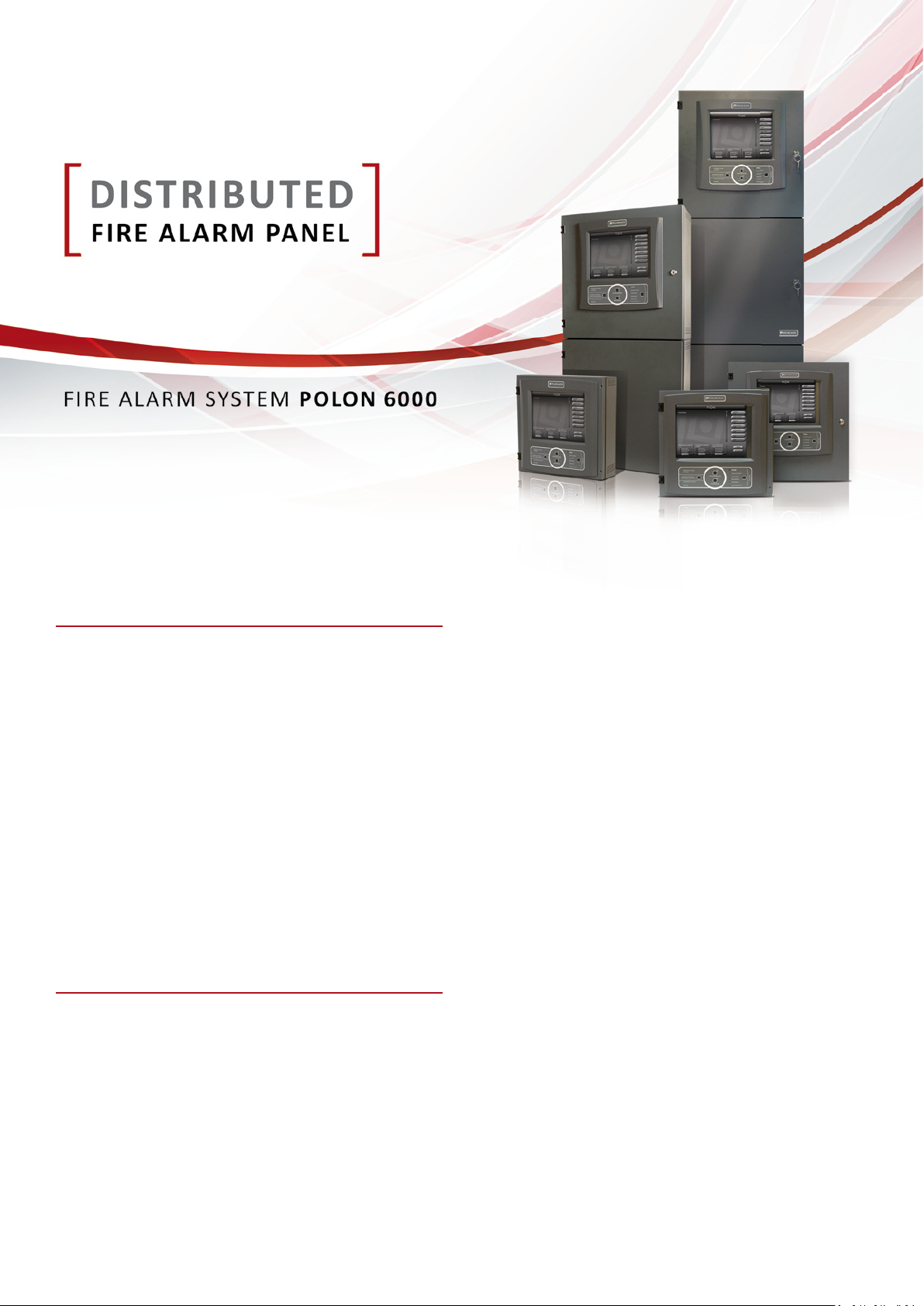
The POLON 6000 control panel
with a distributed architecture
The addressable, interac ve POLON 6000 re alarm system is a set
of latest technology equipment, designed for very fast detec on
and signaling of re, precise indica on of re origin, control of re
protec on safety devices, and informa on of appropriate interven-
on services or building guards about re. It enables protec on of
mid-size, large and very large facili es, especially so called “intelli-
gent” buildings with huge amount of re protec on safety devices.
POLON 6000 can be easily integrated with variety of exis ng buil-
ding management systems. Due to its speci c features it enables
to arrange perfect set of necessary devices, well- ed to site re-
quirements.
The POLON 6000 system is based on newly designed control panels
with distributed architecture and new range of line elements. All
devices of the POLON 6000 system meet requirements of the latest
edi on of EN 54 European Standards.
The POLON 6000 control panel design was based on the idea of a
module device with a distributed architecture. It consists of many
unified modules of various types, installed inside standardized ca-
binets. Cabinets can be arranged as separate units or combined
in sets (so called nodes) and can be located in different places of
site area, even if those locations are distant. All modules within
one node and nodes between themselves are connected with
a common, doubled (redundant) digital communication bus.
Each control panel can be flexibly assembled with modules and no-
des well-fitted to individual building requirements. Such solution
enables the arrangement of the control panel equipment, installed
in required locations. This provides maximum optimization of the
system, reduction costs of installation. All that is possible thanks to
implementation of doubled main processor controllers, communi-
cation buses and connections between nodes.
The POLON 6000 control panel consists of the PSO-60 operation
panels with 10’’ touch screen, functional modules: detection lines
MLD-61 and MLD-62, input-output MKS-60, relay outputs MPK-60,
signalling outputs MWS-60, conventionale line module MLK-60,
high current relay outputs MPW-61, supervision inputs MWK-60,
supply MZP-60 and transmission MTI-61, MTI-62, MTI-63 v2.
PSO panels and modules are installed inside the cabinets with stan-
dard dimensions, which can be mechanically binded. A set of such
mechanically connected cabinets create a control panel node. The
control panel need to have at least one node in which main con-
trol panel PSO-60 (having number 1) is installed. This is the “main
node” of the control panel. There is always only one “Main node”
in the system. The rest of elements (modules) of the control panel
is configured in form of external nodes which are connected to
the “main node”. The communication between nodes is provided
by double cable connection (RS-485) or double fiber optic cables.
Each node shall be equipped – depending on the size of node and
expected current consumption – with one or more supply modules.
Each node can contain line modules with connected detection lines,
input-output modules for direct control or supervision of fire safety
devices. In each external node the PSO-60 panel can be implemen-
ted, acting as the parallel operation panel.


