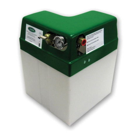
Advantage Controls GF User manual

1
Manual
Model GF
Digital Glycol
Feeder with
NANO
Installation
Maintenance
Repair
Manual
Advantage Controls
4700 Harold-Abitz Dr.
Muskogee, OK 74403
Phone: 800-743-7431
Fax: 888-686-6212
www.advantagecontrols.com 03/2021
GFPUMP-X
Style Pump

2
Table of Contents
I. Introduction .................................................................................................2
............................................3
III. Installation...................................................................................................4
Electrical Wiring ...............................................................................4
Mounting Instructions.......................................................................4
Typical Installation and Measurements ............................................5
Relay and Logic Cards.....................................................................6
Start Up and Test Procedure / Recommendations...........................7
IV. Front Panel Description ..............................................................................7
V. System Operation Overview .......................................................................7
Description of Set Up Menus ...........................................................7
VI. NanoTron mA Menu Map............................................................................8
VII. Parts List...................................................................................................10
VIII. Troubleshooting and Maintenance............................................................ 11
IX. Warranty ...................................................................................................13
Reference Chart % Propylene Glycol.............................................................................14
Reference Chart % Ethylene Glycol...............................................................................14
I. Introduction
The Advantage Controls Glycol Feed Systems are design to regulate pressure in closed loop Hydronic
Heating and Cooling applications.
Advantage Controls micro-processor base controller reads a solid state pressure transducer, displays
system pressure, and uses a keypad for the entry of control parameters. The micro-processor has built
in real-time clock and memory back-up for all user settings, in case of power interruptions. Setting for
all functions are made using the keypad, readings are displayed on a back lit 16 character alphanumeric
display.
Advantage Controls Glycol Feeders are stand alone pre-wired, pre-plumbed systems designed for ease
of installation. Our systems are mounted on a powder coated steel frame with anchor points.
model number against the selection guide for better understanding of your system.
Please read this instruction manual to become familiar with your system.

3
II. ModelNumberingandGeneralSpecications
BUILD A MODEL GF - __ __ __ __ __ __ - __ __
TANK SELECTION
0 = No tank
1 = 55 gallon poly
2 = 100 gallon poly
3 = 30 gallon poly
7 = 150 gallon poly
STAND SELECTION
A = Powder Coated steel stand
B = Powder Coated steel stand w/ mixer bracket
C = Tank top mount (no tank included)
D = Portable stand with built in rollers
PUMP SELECTION
0 = No pump
4 = 10 gpm at 100 PSI; 1 hp
PUMP CONFIGURATION
B = Alternating pumps for single loops
(requires 2 pump selections)
C = Pump plumbed for transfer duty into tank
LOOP SELECTION
0 = No loop
1 = Sch 80 PVC loop; 100 PSI max; 100°F max
2 = Copper/brass loop; 100 PSI max; 180°F max
3 = Carbon steel loop; 100 PSI max
CONTROL SELECTION
M = ETL listed NANO-N with alarm buzzer and dry contact
OPTIONS
1 = 240V
5 = Position backcheck to use tank for expansion
H = 0-200 PSI pressure transducer and gauge
M = Mixer controls (order mixer separate)
Most units include poly tank and stand, low
level switch with audible alarm (100db) with
silence switch, dry contact alarm, pressure
relief valve and plumbing assembly with
pressure gauge.
NOTE: Pump selections represent models
built after 03/2021.

4
III. Installation
Electrical Wiring
The standard digital glycol feeder controller has an internal regulated power supply that will operate in
the range of approximately 100 to 250 VAC on the incoming wiring. Output relay(s) are protected with a
replaceable fuse. Each relay’s output voltage will equal incoming line voltage. The Standard prewired units
are supplied with a 8 foot, 16 AWG, 3 wire grounded, 120 VAC USA power cord for incoming power.
NOTE:Liquidtightttingsandlabeledsignalleadcablesareprovidedforallsignal(lowvoltage)
connections,lowdrumlevelandpressuretransducer.
WARNINGS:
1. The controller should be connected to its own isolated circuit breaker, and for best
results, the ground should be a true earth ground, not shared. Wiring must be done
according to all applicable local codes.
2. Power(linevoltage)mustbedisconnectedwhilemakinganyconnections.Ifpoweris
suppliedtotheunit,linevoltagewillbepresentontherelaycards.
3. Lowvoltagesignalwires(transducer,level,alarm,etc.)shouldneverberuninconduit
withhighvoltagewires.
Mounting Instructions
Select a mounting location that provides the operator easy access to the unit and a clear view of the controller.
The location should be convenient to grounded electrical connections and system plumbing connections.
Mount the glycol feeder stand to a level concrete pad using the ½” mounting holes in the base of the stand.
Concrete pad construction and anchoring bolts must comply with local building codes. The required sample
line plumbing should be connected to the return header of the Hydronic system
WARNING:
Avoid locations that expose the controller to direct sunlight, vapors, vibration,
liquid spills or extreme temperatures; less than 0°F (-17.8°C) or greater than 120°F (50°C).
EMI(electromagnetic interference) from radio transmissions and electric motors can also
causedamageorinterferenceandshouldbeavoided.
!
!

5
Typical Installation and Measurements
System
Connection
Circulation Pump
GFPUMP-X
Style Pump
1/4” bolt hole drilled
3/4” from outside edge
Note: This is for mounting
holes only. Controller will
extend beyond this depth.
GLYCOL STAND FOOT PRINT
C
D
A B C D E
30gal
113.5L
23 ¾”
60.3 cm
51”
129.5 cm
27 ½”
69.8 cm
25 ½”
64.7 cm
30 ½”
77.4 cm
55gal
208.1L
27 ½”
69.8 cm
65”
165.1 cm
27 ½”
69.8 cm
25 ½”
64.7 cm
32”
81.2 cm
100gal
378.5L
31 ¼”
79.3 cm
66”
167.6 cm
37”
93.9 cm
35”
88.9 cm
38”
96.5 cm
B
Side View Shown
E
A

6
+-+-+-
Pulse
Out
mA
OUTPUT
EXT INT
mA OUT
POWER
+-
Flow
Switch
+-+-+
Battery
-
mA
INPUT
Internal
24 VDC
Power
Output
J2
NanoTron-N Logic Card
Contrast
Power
1 2 3
4 5
ON
OFF
If the mA OUT Power switch is on
INT the unit’s internal 24 VDC is
applied to the output. If set for
EXT the external loop out power
supplied is used on the output.
+-+-+-
Pulse
Out
mA OUT
+-
Flow
Switch
+-
WM or
Dig In
+-+-
mA IN Internal
24 VDC
Ext Out
Loop
Power
Input Device +
Input Device -
Jump from 24+
to mA IN +
Wiring for two-wire
input sensors that
need 12-24 VDC
on the loop.
+-+-+-
Pulse
Out
mA OUT
+-
Flow
Switch
+-
WM or
Dig In
+-+-
mA IN Internal
24 VDC
Ext Out
Loop
Power
Input Device mA+
Input Device mA -
Wiring for four-wire
input sensors that
need 12-24 VDC
on power input.
Input Device Power+
Input Device Power-
External
Power for
mA Out
36 VDC
Max
Digital In:
Water
Meter
or Drum
Level
+-+-+-
Pulse
Out
mA
OUTPUT
EXT INT
mA OUT
POWER
+-
Flow
Switch
+-+-+
Battery
-
mA
INPUT
Internal
24 VDC
Power
Output
J2
NanoTron-N Logic Card
Contrast
Power
1 2 3
4 5
ON
OFF
If the mA OUT Power switch is on
INT the unit’s internal 24 VDC is
applied to the output. If set for
EXT the external loop out power
supplied is used on the output.
+-+-+-
Pulse
Out
mA OUT
+-
Flow
Switch
+-
WM or
Dig In
+-+-
mA IN Internal
24 VDC
Ext Out
Loop
Power
Input Device +
Input Device -
Jump from 24+
to mA IN +
Wiring for two-wire
input sensors that
need 12-24 VDC
on the loop.
+-+-+-
Pulse
Out
mA OUT
+-
Flow
Switch
+-
WM or
Dig In
+-+-
mA IN Internal
24 VDC
Ext Out
Loop
Power
Input Device mA+
Input Device mA -
Wiring for four-wire
input sensors that
need 12-24 VDC
on power input.
Input Device Power+
Input Device Power-
External
Power for
mA Out
36 VDC
Max
Digital In:
Water
Meter
or Drum
Level
Switch # Position Function
1 OFF Backlighto;ashesonw/alarm
1 ON Backlighton;ashesow/alarm
2 OFF Normal Operation
2 ON “Burn-in”Mode
3 OFF Normal Operation
3 ON Resets to factory defaults
FUSE
Relay 1
Ribbon
Cable
Relay 2
Power In
H N G
FUSE
POWER SUPPLY
RELAY 1 RELAY 2
Dry
GND
Hot
Neutral
Ground
N. O.
N. C.
Neutral
Ground
N. O.
N. C.
GND
Dry Hot
Relay
1
Relay
2
Relay Card
NO NC
COM
NEU
CONTROL
HOT

7
StartUpandTestProcedure/Recommendations
debris.
2. Check plumbing as it may have become loose from vibrations during shipping.
3. Fill Tank
4. Open isolation valve to system.
5. If there are no leaks verify that the pressure gauge agrees with system pressure. This value may vary do to
connection to Hydronic systems placement.
6. Before applying power to the controller, remove fuse from lower relay enclosure. (There will be two (2) fuses
on dual pump system) Reasoning behind this is, factory settings may not agree with your system and this
gives time for you to set your parameters before applying power to the pump or pumps.
7. Apply power to your system. Plug it in.
8. Once you are familiar with the controller from either reading the instruction manual or trial and error. Proceed
with setting perimeters that are correct for your hydronic system.
IV. Front Panel Description
FORCE
ON/OFF
MENU
1 2
Wed10:59:57am
MENU
FORCE
ON/OFF
ENTER
Press MENU to access menus or go back
one layer in menu structure.
Press FORCE to activate relays manually
again for Off and a third time back to auto.
Press ENTER to go a layer deeper in menu,
to initiate a setting change and to set change.
Use up or down arrows to navigate through
menu selections or setting options.
Use left or right arrows to move cursor
while making a numerical value change.
ENTER
V. SystemOperationOverview
Description of Menus
NanoTron controllers have three modes of operation, Run, Menu and Force. All menus are circular. Pressing the DOWN
key will display the next line of information on the display.
Run- This mode is for normal operation. The control relays will only be automatically active in this mode. In the
status.
The Run menu will display values such as day, time, date and other values depending upon the features
present on the unit. The unit will automatically return to the Run mode if no keys are pressed for three
minutes.
Menu - This mode is used to make adjustments to settings and readings on the controller. To access the Menu
mode from the run screen, press the Menu key. Use the up or down arrow to scroll through the various
menu you will be able to step through that menu’s options with the up or down arrow key.
Force-
to force
same amount of time. Press a third time to go back to automatic Run mode. Unit returns to the Run mode
automatically when the force time has elapsed.

8
Calibration Control Set
Setpoint 500.0
Diff 050.0
Direction: Rise
High Alarm 700.0
Low Alarm 300.0
Limit hh:mm
Calibration
1 Point Cal: Y/N
2 Point Cal: Y/N
20mA Applied: Y/N
Units: PSI
Decimal: XXX.X
4mA = 000.0
20mA = 100.0
Timer Set
Post Control 010% of Cntrl
Limit Time hh:mm
With Control
Limit Time hh:mm
Alarm Control
Batch Run Tim mm:ss
28-Day (Bio) A: All Days
A: All Weeks
A: Start 12:00a
A: Run Time hh:mm
A: Prbld hh:mm
A: Lkout hh:mm
B: All Days
B: All Weeks
B: Start 12:00a
B: Run Time hh:mm
B: Prbld hh:mm
B: Lkout hh:mm
Recycle Off Time hh:mm
Run Time mm:ss
Utility
Clock Set Force Set Diagnostics
Password 0000 Set Time Force On: Both Nano-4-20
Hi Lvl: Open
Set Date FW: ?.?.?
DigIn: Drum 1&2
Set Day & Week Test Keypad
Test Display
R1 Cntrl mm:ss
Reset Cal? N
Pressure Set
ON at: XXX.X
OFF at: XXX.X
High Alarm: XXX.X
Low Alarm: XXX.X
Limit : HH : MM
R2 Timer mm:ss
Feed OK w/Ctrl
Raw A/D: ????
Digi 0/1
If Yes is selected the
current calibration A/D
values are stored.
If a Reset Cal is done
these A/D values are
restored for the 4 & 20.
0-32,767 scale
Identify logic state
of vaious digital
inputs.
4-20 Output
4 mA = 000.0
Sim 4mA: OFF
20mA= 999.9
Sim 20mA: OFF
Pulse Output
HiMax = 0125
HiRate= 700.0
HiMax should
match pump
max stroke/ min
speed rate.
LoRate is sensor
reading desired
for slowest pulse
output.
Hi Rate is sensor
reading for high
pulse rate.
LoRate= 000.0
Set 4 and 20mA
out at desired
sensor reading.
Sim 4 and 20mA
will force output
to either 4 or 20
regardless of
reading.
4mA applied: N
4mA In: 04350
20mA applied: N
20mA In: 21350
Press Enter only
if a 4mA or 20mA
signal is being
received when in
those calibration
screens.
Set the decimal
for displayed
numerical format
and the 4mA and
20mA for what the
value of that range
desired at those
two mA values
CAL 20: 2948
CAL 4: 0590
Set Default? N
The CAL 4 or 20
can be used to
change the signal
of either the 4 or
20 value to match
those two points
with the recieving
device
Disabled
Cal: XX.XX
Simulator: Y/N
4mA Applied: Y/N
For Firmwares prior
to Nano-N 5.1.5.E:
VI. NanoTron mA Menu Map
NanoTron conductivity units have a main menu circle that includes:
Calibration - Calibrating the reading
Pressure Set - Setting the set point and alarms
Timer Set - Select the timer type and run values
Congure - Password, units of measure, and more
4-20Output - Calibrate and set the range of the mA output
Pulse Output - Set the range and speed of the pulse output
Clock Set - Set time, date and week
Force Set - Set the force on time for manual relay activations
Diagnostics - Tests and calibration reset

9
Calibration Control Set
Setpoint 500.0
Diff 050.0
Direction: Rise
High Alarm 700.0
Low Alarm 300.0
Limit hh:mm
Calibration
1 Point Cal: Y/N
2 Point Cal: Y/N
20mA Applied: Y/N
Units: PSI
Decimal: XXX.X
4mA = 000.0
20mA = 100.0
Timer Set
Post Control 010% of Cntrl
Limit Time hh:mm
With Control
Limit Time hh:mm
Alarm Control
Batch Run Tim mm:ss
28-Day (Bio) A: All Days
A: All Weeks
A: Start 12:00a
A: Run Time hh:mm
A: Prbld hh:mm
A: Lkout hh:mm
B: All Days
B: All Weeks
B: Start 12:00a
B: Run Time hh:mm
B: Prbld hh:mm
B: Lkout hh:mm
Recycle Off Time hh:mm
Run Time mm:ss
Utility
Clock Set Force Set Diagnostics
Password 0000 Set Time Force On: Both Nano-4-20
Hi Lvl: Open
Set Date FW: ?.?.?
DigIn: Drum 1&2
Set Day & Week Test Keypad
Test Display
R1 Cntrl mm:ss
Reset Cal? N
Pressure Set
ON at: XXX.X
OFF at: XXX.X
High Alarm: XXX.X
Low Alarm: XXX.X
Limit : HH : MM
R2 Timer mm:ss
Feed OK w/Ctrl
Raw A/D: ????
Digi 0/1
If Yes is selected the
current calibration A/D
values are stored.
If a Reset Cal is done
these A/D values are
restored for the 4 & 20.
0-32,767 scale
Identify logic state
of vaious digital
inputs.
4-20 Output
4 mA = 000.0
Sim 4mA: OFF
20mA= 999.9
Sim 20mA: OFF
Pulse Output
HiMax = 0125
HiRate= 700.0
HiMax should
match pump
max stroke/ min
speed rate.
LoRate is sensor
reading desired
for slowest pulse
output.
Hi Rate is sensor
reading for high
pulse rate.
LoRate= 000.0
Set 4 and 20mA
out at desired
sensor reading.
Sim 4 and 20mA
will force output
to either 4 or 20
regardless of
reading.
4mA applied: N
4mA In: 04350
20mA applied: N
20mA In: 21350
Press Enter only
if a 4mA or 20mA
signal is being
received when in
those calibration
screens.
Set the decimal
for displayed
numerical format
and the 4mA and
20mA for what the
value of that range
desired at those
two mA values
CAL 20: 2948
CAL 4: 0590
Set Default? N
The CAL 4 or 20
can be used to
change the signal
of either the 4 or
20 value to match
those two points
with the recieving
device
Disabled
Cal: XX.XX
Simulator: Y/N
4mA Applied: Y/N
For Firmwares prior
to Nano-N 5.1.5.E:

10
VII. Parts List
Parts List
1. Level wand for 30 gl = ALL-S30; 55 gl = ALL-S42
2. Tank lid for 30 gl = LID-30-C1D; 55 gl =LID-55-C1D
3. Tank for 30gl = AGF-APCT-30; for 55 gl =AGF-APCT-55
4. Pressure relief valve = AGF-PRV
5. Glycol feeder controller = GF-NANO-M
6. Isolation valve = BV-3/4 for PVC; GV-3/4 for copper
7. Back check = CKV-3/4PP for PVC; CKV-3/4B for copper
8. Pressure gauge = AGF-PG
9. Pressure transducer = AGF-PTD (0-100 psi)
AGF-SUCTION
11. Pump = See model number too identify
desired replacement pump output.
1= GFPUMP-1 for 2 gpm @ 150 psi
2= GFPUMP-2 for 3.3 gpm @ 150 psi
3= GFPUMP-3 for 5.5 gpm @ 100 psi
4= GFPUMP-4 for 10 gpm @ 100 psi
Note: This list covers most of our popular models.
For models not covered, consult factory.
PressureReliefValveSpecications
•
• Inlet (bottom) is male threaded, NPT
• Outlet (side) is female threaded, NPT.
• Buna-N disc on machined body seat.
Gallons per Minute at Pressure
Model 50psi 100psi 150psi 200psi 250psi
GFPUMP-1 2.1 2.05 2 1.95 0
GFPUMP-2 3.6 3.4 3.2 3.1 0
GFPUMP-3 5.51 5.5 5.41 0 0
GFPUMP-4 10.2 10.1 10 9.5 9.2
1
2
3
4
5
6
7
8
11
10
6
9
GFPUMP-X
Style Pump

11
VIII. Troubleshooting & Maintenance
The Advantage Glycol Feeder is designed for many years of trouble-free operation. Should a problem occur,
refer to the following to help identify the problem.
NO POWER TO CONTROLLER
1. Disconnect plug from live receptacle.
2. Remove keypad panel to access relay board in the back of the enclosure (see page 6).
3. Locate green 3 position connector in bottom right corner of board and make sure it is securely plugged in with all three
wires tightly screwed down in the connector.
4. Locate logic ribbon cable on left side of relay board and make sure it is securely connected at both ends.
5. Before replacing the panel, do a quick visual of all connections and wiring to ensure no other damage has occurred.
6. Replace panel and secure.
7. Plug in power cord and proceed with Start-up.
8. If power issue was not corrected. Record Model /Serial Numbers and call customer service at 918-686-6211.
PUMP DOES NOT RUN WHEN RELAY INDICATOR IS ILLUMINATED
1. Check fuse and that the fuse holder is secure.
2. Check pump wiring.
3.
PUMP DOES NOT SHUT OFF WHEN TANK IS EMPTY
1.
2. Disconnect level wand connection and short tips together in connector going back to controller (this is low voltage).
Alarm should sound and pump stop when the input sees a closed contact.
have free movement, up and down.
• If No, inspect wire for damage. If no damage visible inspect internal wiring (see page 6).
3. If no resolution is found, record Serial / Model numbers and call customer service.
LOW LEVEL ALARM STAYS ON
1. The low level input goes into alarm when there is a closed contact on the input. Disconnect level wand connection and
2.
3.
4.
5. If no resolution record Model / Serial numbers and call customer service.
PUMP WILL NOT RUN OR BLOWS FUSE
recommended that you replace the pump.
replacement for older models that used a gear pump. The newer pumps may require a new larger suction strainer assembly
and tubing. Here are the models and required suction sizing based on the Pump selection code in the model number (see
model numbering on page 3):
Pump Code Replacement Suction Assembly
1 GFPUMP-1 GF-1-SUCTION includes ½” strainer and 3/8” tubing
2 GFPUMP-2 GF-2-SUCTION includes ½” strainer and ½” tubing
3 GFPUMP-3 GF-2-SUCTION includes ½” strainer and ½” tubing
4 GFPUMP-4 GF-4-SUCTION includes ¾” strainer and ¾” tubing

12
Maintenance
Maintenance and care will depend upon the usage and environment in which the system is subjected to. The
following is the suggested regular maintenance required to keep the glycol feed system operating properly:
TANK AND PLUMBING
Periodically check the piping and tubing to insure proper discharge of the glycol solution. The strainer should
be periodically checked for clogging and wear. The level wand should be removed and cleaned to prevent
clogging.
FEED PUMP
Check for proper operation. If any pump/motor noises, leaks or changes in operation are detected, the pump
PRESSURE RELIEF VALVE
Periodic checking and replacement of the adjustment seal is the only maintenance required.

13
IX. Manufacturer’s Product Warranty
Advantage Controls warrants units of its manufacture to be free of defects in material or workmanship. Liability
under this policy extends for 12 months from date of installation for all aspects of the glycol feeder with the controller
only covered for an additional 12 months. Liability is limited to repair or replacement of any failed equipment or part
proven defective in material or workmanship upon manufacturer’s examination. Removal and installation costs
are not included under this warranty. Manufacturer’s liability shall never exceed the selling price of equipment
or part in question. Advantage disclaims all liability for damage caused by its products by improper installation,
maintenance, use or attempts to operate products beyond their intended functionality, intentionally or otherwise,
or any unauthorized repair. Advantage is not responsible for damages, injuries or expense incurred through the
use of its products.
The above warranty is in lieu of other warranties, either expressed or implied. No agent of ours is authorized to
provide any warranty other than the above.
30DayBillingMemoPolicy
Advantage Controls maintains a unique factory exchange program to ensure uninterrupted service with minimum
downtime. If your unit malfunctions, call 1-800-743-7431, and provide our technician with Model and Serial Number
information. If we are unable to diagnose and solve your problem over the phone, a fully warranted replacement
unit will be shipped, usually within 48 hours, on a 30 Day Billing Memo. This service requires a purchase order and
the replacement unit is billed to your regular account for payment.
The replacement unit will be billed at current list price for that model less any applicable resale discount. Upon
return of your old unit, credit will be issued to your account if the unit is in warranty. If the unit is out of warranty
or the damage not covered, a partial credit will be applied based upon a prorated replacement price schedule
dependent on the age of the unit. Any exchange covers only the controller or pump. Electrodes, liquid end
components and other external accessories are not included.

14

15
- Notes -

16
GettheAdvantageinWaterTreatmentEquipment
Advantage Controls can give you the Advantage in products, knowledge
and support on all of your water treatment equipment needs.
Cooling Tower Controllers
Boiler Blow Down Controllers
Blow Down Valve Packages
Solenoid Valves
Water Meters
Chemical Metering Pumps
Corrosion Coupon Racks
Chemical Solution Tanks
Solid Feed Systems
Feed Timers
Filter Equipment
Glycol Feed Systems
Pre Fabricated Systems
Get the Advantage
5
4
3
2
1
ENTER
HELP
5
4
3
CHANGE
RUN
SET UP
0
9
8
2
1
7
6
HOME
BACK
Other manuals for GF
1
Table of contents
