MF200 and MF300 HYDRONIC SYSTEM FEEDER
INSTALLATION, OPERATION AND MAINTENANCE INSTRUCTIONS
The System Feeder is used to maintain a minimum system pressure within a hydronic heating
or cooling system. It should be used to pressurize the system while system temperature is at
it’s lowest.
Installation Instructions
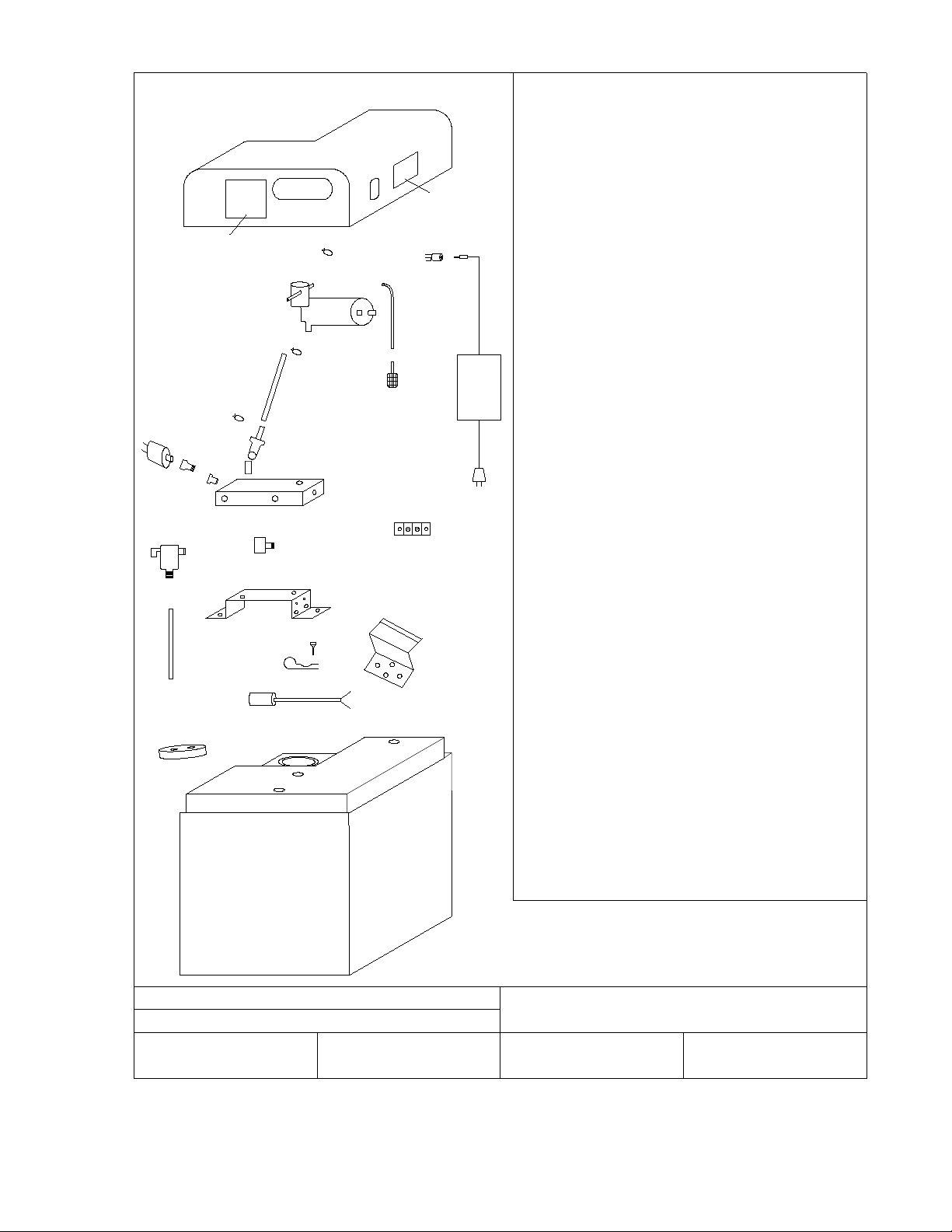
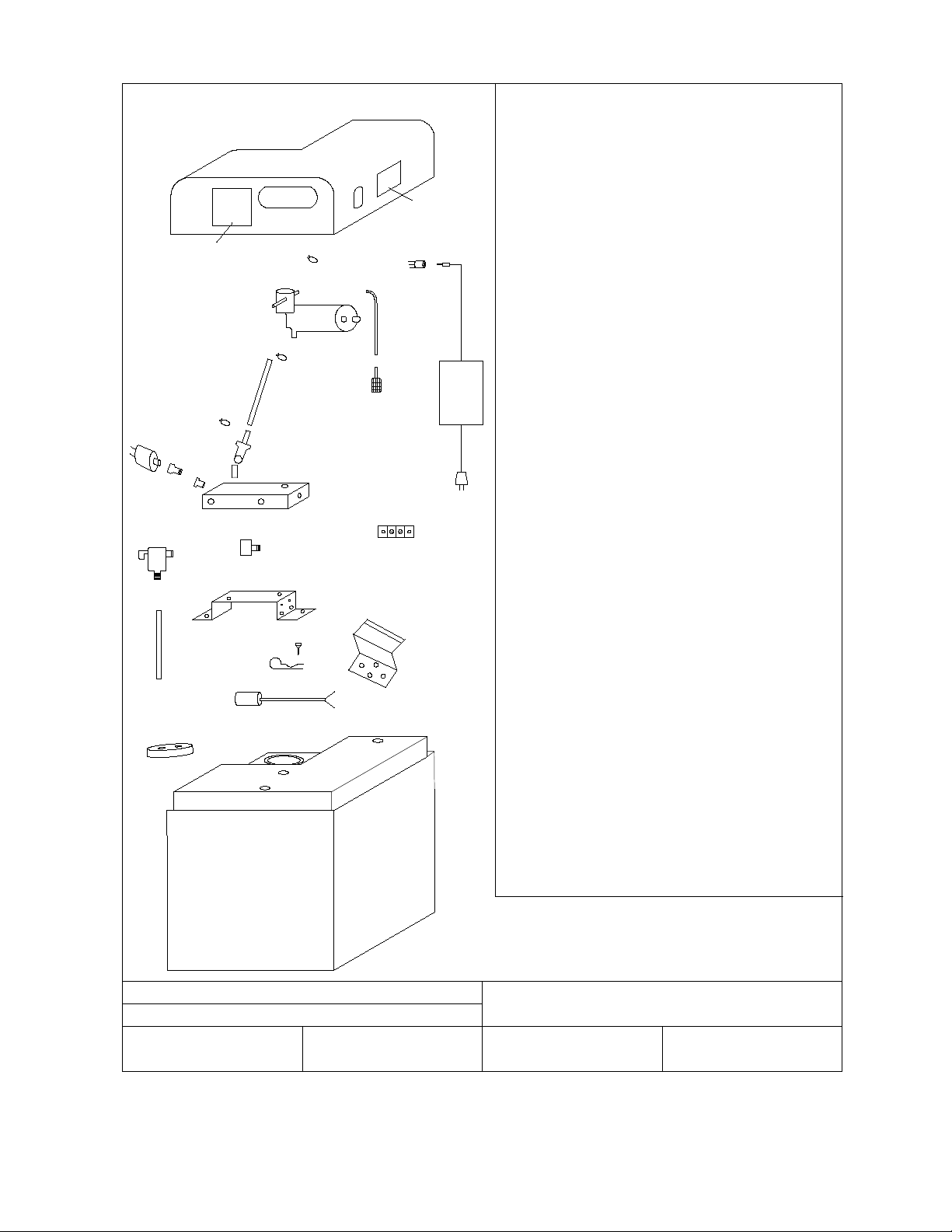
1. Set System Feeder on a secure and level base or in the optional tank shelf.
2. Connect the unit to the system using copper or plastic tubing. Ensure that there is a system
isolation valve installed to allow for isolation of the unit. DO NOT INSTALL A CHECK
VALVE OR PRESSURE REGULATOR BETWEEN SYSTEM FEEDER AND SYSTEM.
3. Mount power supply and secure with mounting bracket. Do not power up System Feeder
until a system connection is made, isolation valve is closed and Feeder valve is set to mix.
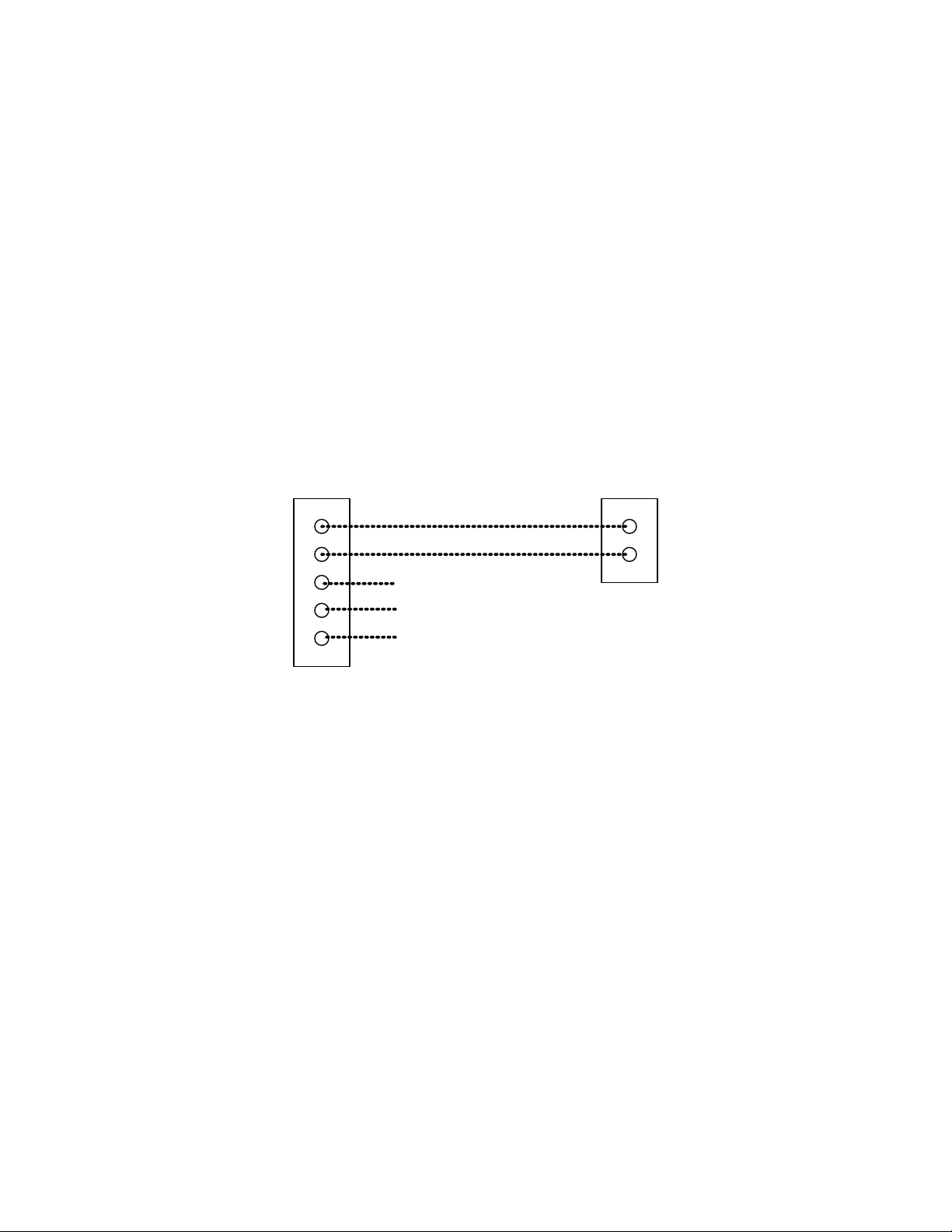
4. If the System Feeder will be connected to an alarm system connect alarm circuit to terminals
below discharge connection.
5. Install proper water/glycol mix in the tank to a level above minimum level indication on tank
scale. A 30-50% Polypropylene Glycol is Recommended.
6. Close system isolation valve, turn feeder valve to vertical position (mix position).
7. Insert DC plug into the System Feeder first, and then plug power supply into 120v outlet.
The red LED in the power supply cord should light up. If it does not, check the fuse and
power receptacle.
8. Once the pump is primed, turn the feeder valve handle to horizontal position (run position),
open system isolation valve and allow pump to pressurize system. If system pressure is
below pressure switch setting (18 psi), the pump will start. The System Feeder will run until
system is pressurized to approximately 18 psi. and shut-off. It may cycle rapidly a number of
times while system pressure stabilizes and while air is removed from the system. The
cycling will stop once system pressure rises above 18 psi due to thermal expansion.
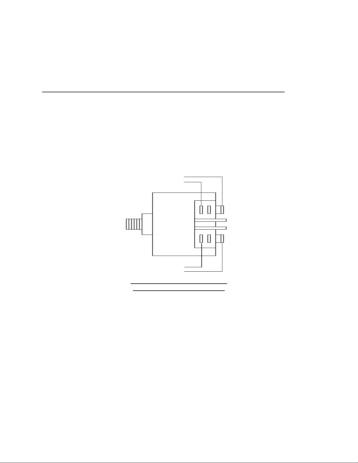
9. If a higher fill pressure is required (up to 25 psi) the internal pressure switch may be
adjusted by turning the center adjusting screw clockwise to increase pressure. Access to the
pressure switch can be gained by lifting the left side of the top cover.
10. The MF200 is shipped with a small amount of 50% propylene glycol (non-toxic) in the
discharge tubing between the pump and the check valve. This is to aid in priming.
Please note that the pressure gauge supplied with the unit may read differently from another
gauge, which may be installed elsewhere in the system. This may be due to gauge calibration or
differences in elevation within the system and should not be a concern.
The System Feeder does not require any scheduled maintenance. Should you wish to test
pump operation, turn mix/purge valve to vertical position to start pump. Turning mix/purge valve
handle to horizontal position will stop pump.
NDUSTRIES LIMITED