Kemppi KEMPOWELD WIRE 200 User manual

KEMPOWELD
WIRE 200
Operation instructions • english
Gebrauchsanweisung • deutsch
Gebruiksaanwijzing • nederlands
Manuel d’utilisation • français
1922030E
0546

2 – KEMPOWELD WIRE 200 / 0546 © KEMPPI OY
CONTENTS
1. PREFACE ...................................................................................................................... 3
1.1. INTRODUCTION ......................................................................................................... 3
1.2. PRODUCT INTRODUCTION ...................................................................................... 3
1.3. OPERATION SAFETY ................................................................................................. 3
2. PARTS OF WIRE FEED MECHANISM WIRE 200 ........................................................ 4
3. KEMPOWELD PANELS ................................................................................................ 5
3.1. OPERATION CONTROL AND CONNECTORS .......................................................... 5
3.2. WIRE FEED PANELS .................................................................................................. 6
3.3. INSIDE OF WIRE FEED UNIT .................................................................................... 6
4. ASSEMBLY OF KEMPOWELD EQUIPMENT ............................................................... 7
5. INSTALLATION .............................................................................................................. 7
5.1. ACCESSORIES CORRESPONDING TO WIRE DIAMETER ...................................... 7
5.2. INSTALLING MIG WELDING GUN ............................................................................. 7
5.3. MOUNTING AND LOCKING WIRE REEL ................................................................... 8
5.4. AUTOMATIC WIRE FEED TO GUN ............................................................................ 8
5.5. ADJUSTING PRESSURE ........................................................................................... 8
5.6. ADJUSTING THE TIGHTNESS OF WIRE REEL BRAKE ........................................... 8
5.7. RETURN CURRENT CABLE ...................................................................................... 8
5.8. SHIELD GAS ............................................................................................................... 9
5.8.1. INSTALLING GAS BOTTLE ........................................................................... 9
6. CONTROL PANELS AND ADJUSTMENTS .................................................................. 9
6.1. WIRE FEED SPEED POTENTIOMETER ................................................................... 9
6.2. BURN BACK TIME ...................................................................................................... 9
6.3. KMW TIMER FUNCTIONS ........................................................................................ 10
7. OPERATION DISTURBANCES ................................................................................... 10
7.1. REGULAR MAINTENANCE OF EQUIPMENT ...........................................................11
8. ORDERING NUMBERS ................................................................................................11
9. TECHNICAL DATA .......................................................................................................11
10. DISPOSAL OF THE MACHINE ................................................................................. 12
11. TERMS OF GUARANTEE ......................................................................................... 12

KEMPOWELD WIRE 200 / 0546 – 3© KEMPPI OY
1. PREFACE
1.1. INTRODUCTION
Congratulations on having purchased this product. Properly installed Kemppi products should prove to be productive
machines requiring maintenance at only regular intervals. This manual is arranged to give you a good understanding
of the equipment and its safe operation. It also contains maintenance information and technical specifications.
Read this manual from front to back before installing, operating or maintaining the equipment for the first time.
For further information on Kemppi products please contact us or your nearest Kemppi distributor.
The specifications and designs presented in this manual are subject to change without prior notice.
In this document, for danger to life or injury the following symbol is used:
Read the warning texts carefully and follow the instructions. Please also study the Operation safety instructions
and respect them when installing, operating and servicing the machine.
1.2. PRODUCT INTRODUCTION
Kempoweld WIRE 200 wire feed unit is used with Kempoweld product range, designed for demanding professional
use with air-cooled MIG guns. Push-pull guns are used with accessory KMW sync.
You can also equip the Kempoweld power source and the wire feed unit with an air-cooled long distance intercon-
nection cable.
1.3. OPERATION SAFETY
Please study these Operation safety instructions and respect them when installing, operating and servicing the
machine.
Welding arc and spatters
Welding arc hurts unprotected eyes. Be careful also with reflecting arc flash. Welding arc and spatter burn unprotected
skin. Use safety gloves and protective clothing.
Danger for fire or explosion
Pay attention to fire safety regulations. Remove flammable or explosive materials from welding place. Always
reserve sufficient fire-fighting equipment on welding place. Be prepared for hazards in special welding jobs, eg.
for the danger of fire or explosion when welding container type work pieces. Note! Fire can break out from sparks
even several hours after the welding work has been finished!
Mains voltage
Never take welding machine inside a work piece (eg. container or truck). Do not place welding machine on a wet
surface. Always check cables before operating the machine. Change defect cables without delay. Defect cables
may cause an injury or set out a fire. Connection cable must not be compressed, it must not touch sharp edges or
hot work pieces.
Welding power circuit
Isolate yourself by using proper protective clothing, do not wear wet clothing. Never work on a wet surface or use
defect cables. Do not put MIG-gun or welding cables on welding machine or on other electric equipment. Do not
press MIG-gun switch, if the gun is not directed towards a work piece.
Welding fumes
Take care that there is sufficient ventilation during welding. Take special safety precautions when welding metals
which contain lead, cadmium, zinc, mercury or beryllium.
This equipment’s electromagnetic compatibility (EMC) is designed for use in an industrial environment.
Class A equipment is not intended for use in residential location where the electrical power is provided
by the public low-voltage supply system.

4 – KEMPOWELD WIRE 200 / 0546 © KEMPPI OY
2. PARTS OF WIRE FEED MECHANISM WIRE 200

KEMPOWELD WIRE 200 / 0546 – 5© KEMPPI OY
3. KEMPOWELD PANELS
3.1. OPERATION CONTROL AND CONNECTORS
Welding current connector of wire feed unit (+ pole)
Main switch (pilot lamp)
Pilot lamp for overheating (power source)
Voltage selecting switches
Return current connector
Fuse of auxiliary transformer (8 A delayed)
Control connector of wire feed unit
Inlet of mains cable

6 – KEMPOWELD WIRE 200 / 0546 © KEMPPI OY
3.2. WIRE FEED PANELS
3.3. INSIDE OF WIRE FEED UNIT
Front panel
Adjustment of wire feed
KMW timer
Trigger function mode (continuous/hold)
Welding mode selection (continuous/spot/cycle arc)
Adjustment of welding mode timing (spot or cycle time)
Welding gun connector (EURO)
Rear panel
Welding current connection
(Kempoweld or interconnection cable)
Control cable connector
(Kempoweld or interconnection cable)
Shielding gas connector
Burn back time (according to filler material and wire feed)
Wire inch switch (wire feed into gun)
Wire reel locking device
Box door lock
Wire feed mechanism

KEMPOWELD WIRE 200 / 0546 – 7© KEMPPI OY
4. ASSEMBLY OF KEMPOWELD EQUIPMENT
Kempoweld power source: Read chapter “Installation” in the Operation Instructions of the power source.
Wire feed unit:
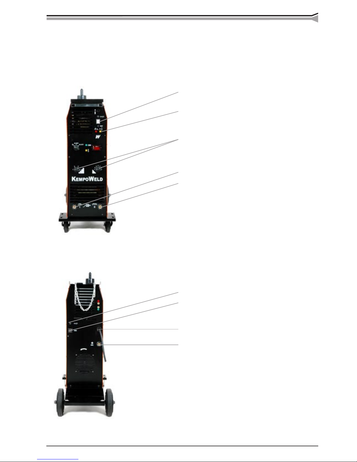
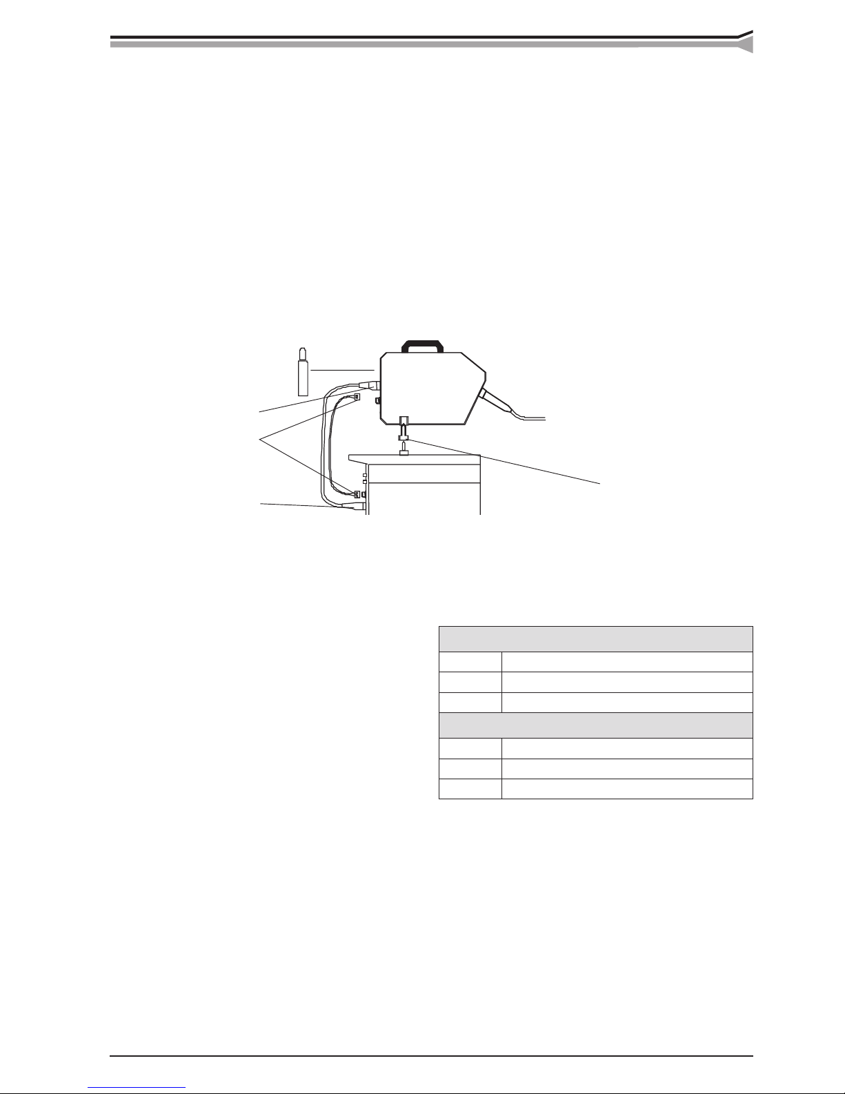
1. Mount wire feed unit on the pin on the power source cover.
2. Mount control cable and welding current cable to the connectors to the rear walls and return current cable
to the connector on Kempoweld front panel.
3. Welding current polarity: When the connection has been done according to the markings, the gun has positive
voltage. In order to change polarity, interchange the welding and return current cable ends connection to the
power source.
4. Connect the interconnection cable plugs with the corresponding sockets in units.
5. If the wire feed unit is mounted to boom, it may not have galvanic contact with lift hook and boom.
6. MIG-gun is connected with EURO connector. Use guide tubes and contact tips according to manufacturer´s
operation instructions. Accessories which are too tight or otherwise unsuitable for the wire type used, will
cause disturbances and excessive stress on accessories.
Bearing bushing
DIX connector
Amphenol connectors
DIX connector
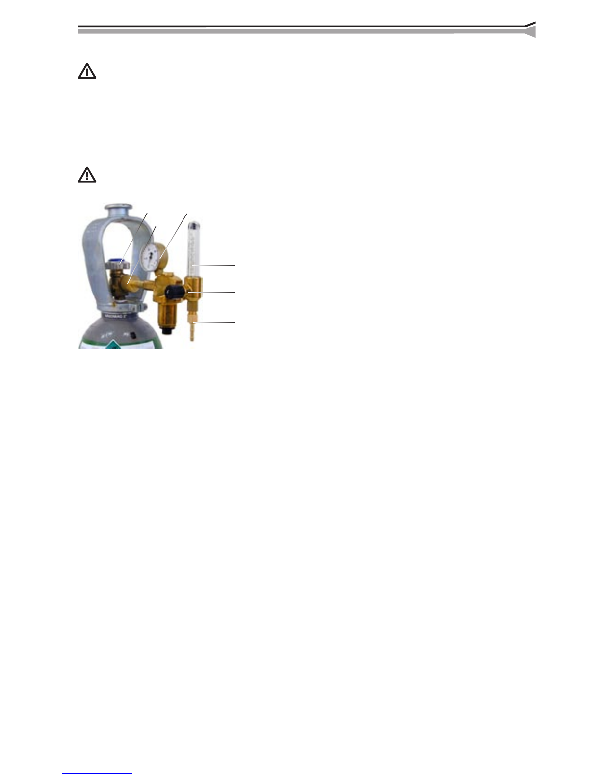
7. Shielding gas hose is mounted to the rear wall of wire feed unit. For installing gas bottle and shielding gas
flow adjustment, see the paragraph Shielding gas.
5. INSTALLATION
5.1. ACCESSORIES CORRESPONDING TO WIRE DIAMETER
Feed rolls
colour filler wire ø mm (inch)
white 0.6 and 0.8 (0.030)
red 0.9/1.0 and 1.2 (0.035, 0.045 and 0.052)
Guide tubes
colour filler wire ø mm (inch)
white 0.6 and 0.8 (0.030)
orange 0.9-1.6 (0.035, 00.45 and 0.052)
The wire feed rolls have two grooves for different filler wire diameters. Correct wire groove is chosen by moving
selecting washer from one side of feed roll to another. The feed rolls and wire guide tubes of wire feed unit have
colour codes in order to make identification easier (see table on page 4). On delivery the Kempoweld WIRE 200 is
equipped with red feed rolls with plain groove and with orange wire guide tubes for welding filler wires of 0.9-1.2
mm (0.035", 0.045" and 0.052").
5.2. INSTALLING MIG WELDING GUN
To ensure problem-free welding, check in the Operation Instructions of the gun that the wire guide tube and contact
tip are in accordance with the manufacturer´s recommendation, and suitable to be used for wire feed diameter
and type in question. An overly tight wire guide tube may cause excessive stress on wire feed unit, resulting in
disturbances in wire feed.
Screw the snap connector of gun tightly, to avoid voltage losses on connecting surface. A loose connection will heat
gun and wire feed unit. After tightening, check that guide tube inside connector is not in contact with feed rolls.
The wire feed rolls are available with plain groove,
knurled groove and with trapezoidal groove for different
purposes.
Feed rolls with plain groove:
1. Universal feed roll for welding of all kind of wires.
2. Special feed rolls for heavy duty use.
Feed rolls with knurled groove:
Special feed roll for cored wires and steel wires.
Feed rolls with trapezoidal groove:
Special feed roll for aluminium wires.

8 – KEMPOWELD WIRE 200 / 0546 © KEMPPI OY
5.3. MOUNTING AND LOCKING WIRE REEL
– Release locking nails of wire reel hub by turning locking knob
to the position OPEN.
– Put the reel at its place. Note the rotating direction of reel!
– Turn locking knob to the position LOCKED.
Check filler wire reel for no protruding parts, which could e.g. chaff against chassis or wire feed unit
door. Dragging parts could expose chassis of wire feed unit under voltage.
5.4. AUTOMATIC WIRE FEED TO GUN
Automatic wire feed makes the change of wire reel quicker. The pressure on feed rolls need not be released and
filler wire goes automatically to correct wire line.
– Make sure that the groove of feed roll matches the diameter of
welding wire used. Feed roll groove is selected by moving the
groove selection washer. Also the selector plate for changing
the feed roll groove has to be moved similarly. (see table on
page 4).
– Release the wire end from the reel and cut off the bent length.
Be careful that the wire does not spill from the reel to the sides!
groove selecting washer
– Straighten approximately 20 cm of the wire. Ensure that the wire end has no sharp edges, if necessary file
them off. A sharp edge may damage the wire guide tube and contact tip of welding gun.
– Draw a piece of loose wire from wire reel. Feed wire through back liner to feed rolls. Do not release the
pressure of the feed rolls!
– Press the gun switch or wire inch switch and feed a piece of wire through feed rolls to the gun. Ensure that
wire is in the grooves of both feed rolls!
– Hold down the switch until the wire has come through the contact tip.
Automatic feed may sometimes fail with thin wires (Fe, Ss: 0,6...0,8 mm, Al, Fc: 0,8...1,0 mm). In this case,
open feed rolls and feed the wire through manually.
5.5. ADJUSTING PRESSURE
Adjust the pressure of feed rolls with control screw, so that the wire is fed into the wire guide tube evenly, and
allows a little braking when coming out from the contact tip, without slipping on the feed rolls.
Excessive pressure causes flattening of the filler wire and damage to the coating. It also causes friction
and undue wear of the feed rolls.
5.6. ADJUSTING THE TIGHTNESS OF WIRE REEL BRAKE
Brake force is adjusted through a hole in the locking device
of reel hub by tightening/loosening the adjustment screw with
a screwdriver.
Adjust the brake force so big that the wire does not slip from
the full reel when the reel stops rotating. The need for brake
force is increased with wire feed speed.
Standard accessory: 200 mm wire reel adaptor
Make sure that the welding gun is designed for the maximum welding current! Do not use a damaged
welding gun!
5.7. RETURN CURRENT CABLE
Fasten earth clamp of return current cable carefully, preferably direct to welding piece. Contact surface of the clamp
should always be as large as possible.
Clean the fastening surface from paint and rust!
Use copper cables in your Kempoweld equipment. A too small cross-sectional area might cause overheating of
connectors and insulations.
LOCKED OPEN
groove selecting washer
adjusting screw

KEMPOWELD WIRE 200 / 0546 – 9© KEMPPI OY
A
B
C
D
E
F
G
5.8. SHIELD GAS
Handle gas bottle with care. There is a risk for injury if gas bottle or bottle valve is damaged!
For welding stainless steels, mixed gases are normally used. Check that the gas bottle valve is suitable for the gas.
The flow rate is set according to the welding power used in the job. A suitable flow rate is normally 8 - 10 l/min.
If the gas flow is not suitable, the welded joint will be sporous. Contact your local Kemppi-dealer for choosing
gas and equipment.
5.8.1. Installing gas bottle
Always fasten gas bottle properly in vertical position in a special holder on the wall or on a carriage.
Remember to close gas bottle valve after having finished welding.
Parts of gas flow regulator
A Gas bottle valve
B Press regulation screw
C Connecting nut
D Hose spindle
E Jacket nut
F Gas bottle pressure meter
G Gas hose pressure meter
The following installing instructions are valid for most of the gas flow regulator types:
1. Step aside and open the bottle valve (A) for a while to blow out possible impurities from the bottle valve.
2. Turn the press regulation screw (B) of the regulator until no spring pressure can be felt.
3. Close needle valve, if there is one in the regulator.
4. Install the regulator on bottle valve and tighten connecting nut (C) with a wrench.
5. Install hose spindle (D) and jacket nut (E) into gas hose and tighten with hose clamp.
6. Connect the hose with the regulator and the other end with the wire feed unit. Tighten the jacket nut.
7. Open bottle valve slowly. Gas bottle pressure meter (F) shows the bottle pressure. Note! Do not use the
whole contents of the bottle. The bottle should be filled when the bottle pressure is 2 bar.
8. Open needle valve if there is one in the regulator.
9. Turn regulation screw (B) until hose pressure meter (G) shows the required flow (or pressure). When regulating
flow amount, the power source should be in switched on and the gun switch pressed simultaniously.
Close bottle valve after having finished welding. If the machine will be out of use for a long time, unscrew the
pressure regulation screw.
6. CONTROL PANELS AND ADJUSTMENTS
6.1. WIRE FEED SPEED POTENTIOMETER
The wire feed speed is adjusted with the potentiometer on the front panel, see the chapter Panels. The potentiometer
has a memory scale for max. speeds of 18 m/min.
6.2. BURN BACK TIME
Different filler materials and shielding gases behave in different ways in the completion of welding. The welding
current should be selected for a burn back time suitable for the welding work.
If you try to cease welding with an unsuitable burn back time, the wire will burn in the contact tip, there will be a
too large amount of wire at the wire end, or the wire will stick at the stopping point.
Factors influencing the delay:
The requred burn back time depends a lot of the wire feed speed. For low wire feed speeds always select a short
burn back time.

10 – KEMPOWELD WIRE 200 / 0546 © KEMPPI OY
1 3 4 2 5
Spot, cycle arc and continuous welding (only in the 2-sequence procedure)
Spot welding
1. Set the spot time with potentiometer.
2. Press the gun switch: welding starts
3. Welding ends automatically after the preset time.
Cycle arc welding
1. Set the welding cycle time with the potentiometer. The pause time is adjusted automatically.
2. Press the gun switch: cycle welding is continued as long as the switch remains pressed.
7. OPERATION DISTURBANCES
The use and working environment of the equipment should be taken into consideration when planning the maintenance
of the wire feed unit. Careful use and preventive maintenance will help to ensure problem-free operation.
The following maintenance operations should be carried out at least every six months:
Check:
– The wear of feed roll grooves. Excessive wear of grooves will cause problems in wire feed.
– The wear of wire guide tubes in wire feed unit. Worn-out feed rolls and wire guide tubes should be
replaced.
– The wire guide tube in the gun should be set as close to the feed rolls as possible, but not in contact with
them. The wire must be in a straight line from the end of the tube to the feed roll groove.
– Reel brake adjustment
– Electric connections
* Oxidised couplings must be cleaned.
* Loose couplings must be tightened.
Clean dust and dirt from the equipment.
In case of problems contact your Kemppi dealer.
When using compressed air, always use proper eye protection.
In the instruction labels of filler wires, starting points for adjustment are
given. Fine-adjustment should be carried out case-specific.
1. Aluminium melts much quicker than other materials, so the burn
back time can be shorter.
2. Steel and especially flux cored wires require a longer burn back time
than stainless materials.
3. Thicker filler wires require a longer time. Also, when the wire feed
speed increases the burn back time must be extended.
4. Memory scale for potentiometer.
5. Wire inch
Welding with the 2-sequence trigger procedure
1. Switch pressed: welding starts
2. Switch open: welding stops
Welding with the 4-sequence trigger procedure
1. Switch pressed: shielding gas flows
2. Switch open: welding starts
3. Switch pressed: welding stops
4. Switch open: gas flow stops after the post gas time
Wire inch
With wire inch, wire feed motor and mechanism can be operated without starting the power source.
The filler wire can be driven into the wire feed unit and gun also by pressing the welding gun switch, but then the
power source will start and the wire becomes live, which can cause a danger of accidental contacts with surrounding
objects!
6.3. KMW TIMER FUNCTIONS
2 / 4-sequence procedure

KEMPOWELD WIRE 200 / 0546 – 11© KEMPPI OY
7.1. REGULAR MAINTENANCE OF EQUIPMENT
Kemppi service workshops make special service contracts with customers about regular maintenance.
The major points of the maintenance are:
– Cleaning the equipment
– Checking and maintenance of the welding tools
– Checking connectors, switches and potentiometers
– Checking electric connections
– Inspecting metering units
– Checking mains cable and plug
– Replacing damaged parts or parts in bad condition
– Maintenance testing. Operation and performance of the equipment are checked,
and the values are adjusted when necessary with the test equipment.
8. ORDERING NUMBERS
Wire feed unit
Kempoweld WIRE 200 62172001
Accessory
P500 transport unit (feeder) 6185265
Hub for wheel reel 4289880
Power source
Kempoweld 2501 240 V 6211255
MIG gun
KMG 25 3 m 6252123
Interconnection cable
KW 35-5-GH 5 m 6260355
Return current cable
35 mm2 5 m (part 7) 6184311
9. TECHNICAL DATA
The products meet the conformity
requirements of CE-marking.
WIRE 200
Working voltage 30 VAC
Connection power 150 VA
Loading capacity 40 % ED 400 A
(nominal values) 60 % ED - - -
100 % ED 260 A
Operation principle 2-roll drive
Diameter of wheel roll 32 mm
Wire feed speed 0...18 m / min
Filler wires ø Fe, Ss 0,6...1,2 mm
ø Cored wire 0,8...1,6 mm
ø Al 1,0...1,6 mm
Wire reel max. weight 20 kg
max. size ø 300 mm
Gun connector Euro
Operation temperature range -20...+40 °C
Storage temperature range -40...+60 °C
Degree of protection IP 23C
Dimensions lenght 570 mm
width 210 mm
height 440 mm
Weight 12 kg
twice
a year

12 – KEMPOWELD WIRE 200 / 0546 © KEMPPI OY
10. DISPOSAL OF THE MACHINE
Do not dispose of electrical equipment together with normal waste!
In observance of European Directive 2002/96/EC on Waste Electrical and Electronic Equipment and
its implementation in accordance with national law, electrical equipment that has reached the end of its
life must be collected separately and returned to an environmentally compatible recycling facility. As
the owner of the equipment, you should get information on approved collection systems from our local
representative.
By applying this European Directive you will improve the environment and human health!
11. TERMS OF GUARANTEE
Kemppi Oy provides a guarantee for products manufactured and sold by them if defects in manufacture and materials
occur. Guarantee repairs must be carried out only by an Authorised Kemppi Service Agent. Packing, freight and
insurance costs to be paid by orderer. The guarantee is effected on the date of purchase. Verbal promises which do
not comply with the terms of guarantee are not binding on guarantor.
Limitations on guarantee
The following conditions are not covered under the terms of guarantee: defects due to natural wear and tear, non-
compliance with operating and maintenance instructions, connection to incorrect or faulty supply voltage (including
voltage surges outside equipment spec.), incorrect gas pressure, overloading, transport or storage damage, fire of
damage due to natural causes i.e. lightning or flooding.
This guarantee does not cover direct or indirect travelling costs, daily allowances or accommodation. Note: Under
the terms of guarantee, welding torches and their consumables, feeder drive rolls and feeder guide tubes are not
covered. Direct or indirect damage due to a defective product is not covered under the guarantee. The guarantee
is void if changes are made to the product without approval of the manufacturer, or if repairs are carried out using
non-approved spare parts.
The guarantee is also void if repairs are carried out by non-authorised agents.
Undertaking guarantee repairs
Guarantee defects must be informed to Kemppi or authorised Kemppi Service Agents within the guarantee period.
Before any guarantee work is undertaken, the customer must provide proof of guarantee or proof of purchase, and
serial number of the equipment in order to validate the guarantee. The parts replaced under the terns of guarantee
remain the property of Kemppi.
Following the guarantee repair, the guarantee of the machine or equipment, repaired or replaced, will be continued
to the end of the original guarantee period.

KEMPPI OY
PL 13
FIN – 15801 LAHTI
FINLAND
Tel (03) 899 11
Telefax (03) 899 428
www.kemppi.com
KEMPPIKONEET OY
PL 13
FIN – 15801 LAHTI
FINLAND
Tel (03) 899 11
Telefax (03) 7348 398
e-mail: myynti.fi@kemppi.com
KEMPPI SVERIGE AB
Box 717
S – 194 27 UPPLANDS VÄSBY
SVERIGE
Tel (08) 590 783 00
Telefax (08) 590 823 94
e-mail: sales.se@kemppi.com
KEMPPI NORGE A/S
Postboks 2151, Postterminalen
N – 3103 TØNSBERG
NORGE
Tel 33 34 60 00
Telefax 33 34 60 10
e-mail: sales.no@kemppi.com
KEMPPI DANMARK A/S
Literbuen 11
DK – 2740 SKOVLUNDE
DANMARK
Tel 44 941 677
Telefax 44 941 536
e-mail:sales.dk@kemppi.com
KEMPPI BENELUX B.V.
Postbus 5603
NL – 4801 EA BREDA
NEDERLAND
Tel +31 (0)76-5717750
Telefax +31 (0)76-5716345
e-mail: sales.nl@kemppi.com
KEMPPI (UK) Ltd
Martti Kemppi Building
Fraser Road
Priory Business Park
BEDFORD, MK443WH
ENGLAND
Tel 0845 6444201
Fax 0845 6444202
e-mail: sales.uk@kemppi.com
KEMPPI FRANCE S.A.
65 Avenue de la Couronne des Prés
78681 EPONE CEDEX
FRANCE
Tel (01) 30 90 04 40
Telefax (01) 30 90 04 45
e-mail: sales.fr@kemppi.com
KEMPPI GmbH
Otto – Hahn – Straße 14
D – 35510 BUTZBACH
DEUTSCHLAND
Tel (06033) 88 020
Telefax (06033) 72 528
e-mail:sales.de@kemppi.com
KEMPPI SP. z o.o.
Ul. Piłsudskiego 2
05-091 ZA¸BKI
Poland
Tel +48 22 781 6162
Telefax +48 22 781 6505
e-mail: info.pl@kemppi.com
KEMPPI WELDING
MACHINES AUSTRALIA PTY LTD
P.O. Box 404 (2/58 Lancaster Street)
Ingleburn NSW 2565, Australia
Tel. +61-2-9605 9500
Telefax +61-2-9605 5999
e-mail: info.au@kemppi.com
www.kemppi.com
Ver. 9
Table of contents
Other Kemppi Wire Feeder manuals