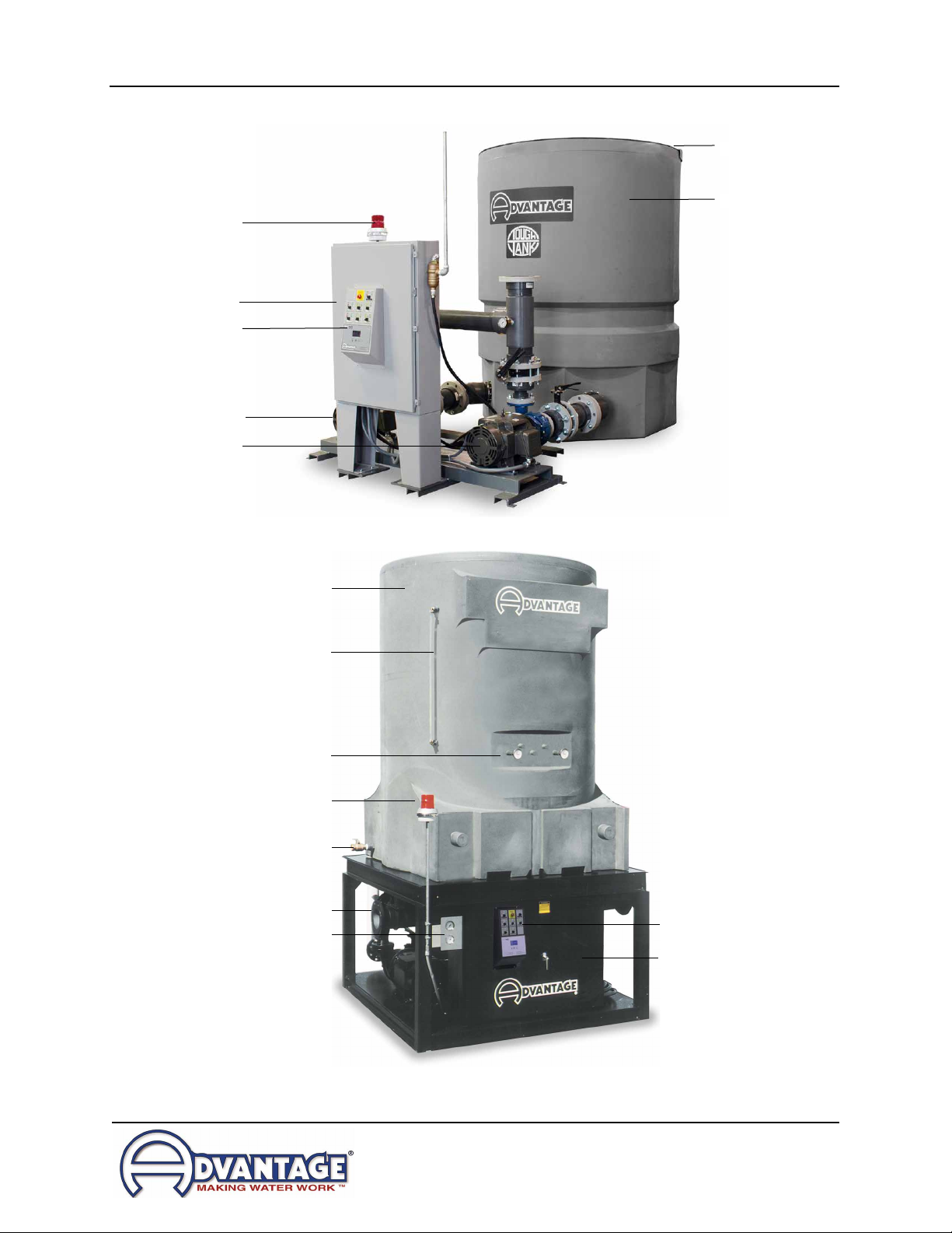
TTK Series Polyethylene Pump Tank Station with Checkmate Control System
Page: 8
ADVANTAGE ENGINEERING, INC.
525 East Stop 18 Road Greenwood, Indiana 46142
317-887-0729 Fax: 317-881-1277
Service Department Fax: 317-885-8683
2.1 INSTALLATION DRAWINGS
A. A number of typical drawings have been provided within this manual and with the unit. It
is necessary to review all drawings supplied to assure proper installation.
B. Contactthefactoryfortheelectricaldiagramthatisspecictoyourunit.
C. You will need the unit serial number when contacting the factory.
2.2 PUMP BASE TO TANK MATING INSTRUCTIONS
A. The following instructions detail the mating of the pump base to the polyethylene tank.
Refer to the drawing on the next page.
B. Unless otherwise noted, all necessary parts have been supplied by the factory.
C. Optional standby pump, alarm automatic water make-up and control console are shown
in the drawing. Not all systems are supplied with these options.
D. Pleasenotethatthecontrolconsoleisshown‘offbase’fordrawingpurpose’sonly.
E. Pump discharge manifold and sight glass are not shown in the drawing.
F. Mate the pump base to the tank.
2.3 PLANT WATER DISTRIBUTION
A. Please note that all material used in the installation should be rated for 150°F and 200 psi
minimum. Also note that the materials should have the equivalent diameter or larger of
their process connections.
B. Plant water distribution system design is critical to maximum performance of the system.
Careful attention should be paid to the pipe sizing, length of runs, number of elbows, tees
andvalving,asspecied.Normally,themostsuccessfulinstallationsarethosewhich
insuremaximumowsandminimumpressuredrops.
C. All water distribution piping should be properly braced to prevent sway and undue stress.
Brace all pipes to assure no excess loads or strains are applied to the unit. Insulate all
pipes to control excessive condensation and to help maintain set temperature to the
process (on chilled water systems).
2.4 WATER TREATMENT
A. A water treatment system must be part of any cooling tower or chilled water
system installation. The services of a professional qualied water treatment
company is required. A water treatment system typically consists of a plan to
control scaling, corrosion and biological growth. Failure to control the quality of
the water can result in premature unit failure, fouling of plant wide heat transfer
surfaces and biological growth that can cause sickness and even death.
B. Keeping the water in a cooling tower or chilled water system clean has benet
by reducing scale and fouling and ensuring that the cooling process is operating