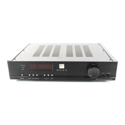
AEB ADVANCED NATIVE TECHNOLOGIES BBA 240 User manual

MULTI-ZONE P.A. AMPLIFIER
AMPLIFICATORE P.A. MULTI-ZONA
AMPLIFICATEUR P.A. MULTI-ZONES
MEHRZONEN-PA-VERSTÄRKER
AMPLIFICADOR MULTIZONA PA
EN USER MANUAL | SECTION 1
IT MANUALE D’USO | SEZIONE 1
FR NOTICE D’EMPLOI | SECTION 1
DE BEDIENUNGSANLEITUNG | KAPITEL 1
ES MANUAL DE USO | SECCIÓN 1

ENGLISH
BBA 240 | User manual
2
3
User manual | BBA 240
TABLE OF CONTENTS
1| Introduction 3
2| Installation 4
3| Description 5
3.1 | Inputs & controls 5
3.1.1 | Front panel 5
3.1.2 | Rear panel 7
4| Bluetooth®10
5| Connections 11
6| Troubleshooting 12
7| Technical specications 13
8| Notes 15
The warnings in this manual must be observed together with the
“USER MANUAL - SECTION 2”.
PACKAGE CONTENT
• 1x 5-channel 4-zone P.A. amplier
- n.1 mains cord (VDE)
• 1x User manual - Section 1
• 1x User manual - Section 2
1| INTRODUCTION
Thank you for choosing a A.N.T - Advanced Native Technologies
- product!
In this multi-zone P.A. amplifier we have put our passion and our
technological background gained over the years, to offer products that
meet your needs, maintaining the quality over time.
Specically designed for an immediate and user-friendly application,
meeting the needs of those who are looking for a perfect solution to provide
amplication to premises and multi-zone venues.
Characterized by an elegant and contemporary prole, this amplier perfectly
combines great quality professional features and exceptional value like:
• 5 input channels, 4 mic/line channels with 48V Phantom power
for condenser microphones;
• Bluetooth®connection for audio streaming via smartphone/tablet;
• Gain, MUTE and 2-band EQ for each channel;
• 4 assignable zones, with dedicated pre-listening;
• Independent volume and level indicator for each zone;
• Monitor and headphones independent volumes,
with specic level indicator;
• Total compatibility with BBM BP / WP installation speakers.
Please, dedicate some minutes to read this instruction manual in order to
quickly achieve the best performances from this product.
For safety precautions, warranty and disposal, please refer to attached
Section 2.
For further information about all A.N.T products catalog, please visit our
website: www.ant-intomusic.com.

ENGLISH
BBA 240 | User manual
4
5
User manual | BBA 240
2| INSTALLATION
The amplier features:
A| Standard 19 "rack mounting ears
B| Front handles for lifting and installing the unit
C| Sturdy sheet metal frame, 3U height
D| Anti-slip rubber feet - removable for rack mounting of the unit
3| DESCRIPTION
3.1 | INPUTS & CONTROLS
3.1.1 | FRONT PANEL
1 ZONE SELECTOR (CH1-CH5)
Independent selectors for assigning
input signals to each of the 4 zones.
2 GAIN (CH1-CH5)
This knob adjusts the gain of the
channel signal, turn the knob to the
right to raise the level or to the left
to decrease it.
3 HIGH (CH1-CH5)
This knob boosts or cuts high
frequencies to get the right mix
with any musical genre and in any
environment.
4 LOW (CH1-CH5)
This knob boosts or cuts low
frequencies to get the right mix
with any musical genre and in any
environment.
5 MUTE & LED (CH1-CH5)
Pressthisbuttontomutetheselected
channelsource.ThelitLEDindicates
command activation.
6 VOL (CH1-CH5)
Use this knob to adjust the channel
volume. Turn it to the right to raise
the level or to the left to decrease it.
1
2
3
4
6
5
C A A C
C
A AB B B B
D
D

ENGLISH
BBA 240 | User manual
6
7
User manual | BBA 240
7 PAIR AND BLUETOOTH®LED
Initializing Bluetooth®sync with
your device, the LED shows the
connection status; audio streaming
volume control is adjusted by
channel knob 5.
For instructions on synchronizing
and connecting your devices, refer
to chapter 4 - BLUETOOTH®.
8 VOLUME & VU METER
(ZONE 1-4)
The LED ladder shows the level of
signal output for each zone. The
volume of each zone is controlled by
the correspondent VOLUME knob,
turn it to the right to raise the level
or to the left to decrease it.
9 MONITOR PHONES
(ZONES 1-4)
Pressthisbuttontoassignthesignal
of each zone to the PHONES and
MONITOR controls.
10 PHONES VOLUME
Adjust this knob to set the PHONES
output level. The headphone allows
you to monitor the signals of the 4
ZONES.
11 MONITOR VOLUME
Adjustthis knob toset theMONITOR
output level.
12 PHONES OUTPUT
Outputforconnectiontoheadphones
with a 6.35mm stereo jack socket.
NOTE: Carefully adjust the volume
of the PHONES knob, thus avoiding
temporary or permanent damage to
your hearing.
13 MONITOR OUTPUT LEVEL
This LED ladder indicates the output level of the MONITOR section.
14 ON LED
Unit power on indicator.
15 POWER ON/OFF
Use this switch to turn ON/OFF the unit.
NOTE: for correct operation always turn on the amplier last and turn
off the amplier rst.
Before turning on the amplier, make sure that all the volume knobs
are at minimum.
3.1.2 | REAR PANEL
1 COOLING FAN
AND VENTILATION SLOTS
The cooling process of the
amplifier and temperature
control within law limits are
ensuredbyproperventilation
of the system, thus it’s
recommended to don’t
obstruct or cover in any way
rear panel ventilation slots.
11
14
10
8
7
9
12
15
13
1

ENGLISH
BBA 240 | User manual
8
9
User manual | BBA 240
2 LINE OUT MONITOR
Monitor signal output to be connected to an amplier, recorder or any other external
device capable of receiving line level signals.
3 MONITOR1W8Ω
Monitor signal output to connect a passive speaker to listen the MONITOR signal.
4 PRIORITY
By short-circuiting, via an external electrical switch or button, these terminals, the
inputs 2-5 audio signals are attenuated, giving priority to input 1 and TEL.
5 TEL PAGING
This balanced connector allows you to connect an external auxiliary signal, for
example that of a desktop microphone or a telephone line, with priority over all
the other signals.
6 VOLTAGE SELECTOR
Operating voltage selector. Generally it is not necessary to act on this command
since it is properly set at factory. WARNING: before switching on the device, make
sure that the mains voltage and that of the device match.
7 MAINS INPUT
IEC input socket. Every package is supplied with the necessary power cord, specic
foryourarea.Plug the powercordintothis socket but makesurethedeviceisturned
off before connecting the cable to the mains. For your safety, never disconnect the
grounding prong. The protection fuse is embedded in the electrical socket.
CAUTION:replacethe fuseonlywith one ofthesametype and withthesamevalues.
If the fuse blows repeatedly, contact an authorized service center.
8 GND
Earth connection of the device and electrical ground.
9 TEL ZONE
This dip switch selector allows you to choose to which zones assign the auxiliary
telephone signal to.
10 TEL VOLUME
Usethiscontroltoadjustthephonesignalvolume.Useasmallflat-bladescrewdriver
to rotate the trimmer.
11 BT/LINE SELECTOR & L/R CH INPUTS
This selector allows you to choose the input signal of channel 5 between
BLUETOOTH®and LINE. The LINE signal input for this channel the RCA jacks
located under the selector.
12 SELECTOR & INPUTS CH 1-4
This selector allows you to
choose the type of input signal
of channels 1-4 among the
following options:
- LINE: line level signal
- PHANTOM: condenser
microphone
- MIC: dynamic microphone.
Theinputconnectorisacombo
(XLR F + 6.35mm jack).
6
9
10
78
2 3 4 5
11 12

ENGLISH
BBA 240 | User manual
10
11
User manual | BBA 240
5| CONNECTIONS
WARNING: The total power of all the speakers/loudspeakers wired to
each channel must not exceed the nominal power of the amplier. For
safety reasons, it is recommended that the total power of all speakers
wired to the BBA 240 unit is less than 3/4 of amplier nominal power.
13 LINE OUT BAL/UNBAL (ZONE 1-4)
Unbalanced/balanced outputs of each zone output signal.
14 POWER AMP OUTPUT (ZONE 1-4)
Amplied outputs 4Ω and 8Ω constant impedance systems, or 25V, 70V and 100V
constant voltage systems.
Connect only one amplied output for each zone, respecting the positive and
negative polarities of the amplier and the speakers.
4| BLUETOOTH®
Follow this procedure to synchronize a Bluetooth® device with the amplier:
• When the unit is turned on, the blue LED flashes slowly;
• Press the PAIR button for three seconds until the LED starts flashing quickly, it
indicates the start of synchronization with your smartphone or tablet;
• Now the amplier is shown - with its name BBA 240 - in device Bluetooth®menu,
then select the name to make the connection;
• Once connected, the LED remains lit steadily until the device is disconnected.
14
13
Amplifier
Recorder
Horn speaker
BBM BP/WP Speaker
Column speaker
Mains CD player
AM/FM tuner
Total impedance: 4Ω
Microphone
Desktop microphone
Total impedance: 8Ω
Connection to 25V constant voltage speakers
Connection to 70V constant voltage speakers
Connection to 100V constant voltage speak
ers
Speaker
“VOICE PRIORITY”
contact
AUX signal

ENGLISH
BBA 240 | User manual
12
13
User manual | BBA 240
6 | TROUBLESHOOTING
PROBLEM LED SOLUTION
No sound or very low
sound level Power LED turned off.
Make sure the system is properly
connected to the mains outlet.
Check voltage selector correct position.
Make sure that mains plug is rmly
inserted into the socket.
POWER LED on but low
GAIN of input channel Raise the GAIN level
POWER LED on, GAIN
up but MUTE button
pressed
Raise the MUTE button
POWER LED on but low
VOL of input channel Raise the VOL level
POWER LED on but
low VOLUME of output
zones
Raise VOLUME of the channels.
POWER LED on, all
controls active but
Phantom not activated
Put the input selector in central position,
thus activating the phantom power
All above checked but
there is no sound
Check the connections between the
sources and the inputs.
Distortion PEAK LED on in a zone
Adjust the GAIN of the entrance
Make sure you have not connected a dial
tone to a MIC jack
Check the source level.
Attenuate VOLUME of the specic ZONE
Red LEDs constantly lit
on all ZONES
Attenuate GAIN/VOL of the inputs and/or
zones VOLUME
Muddy sound
Make sure you haven't simultaneously
connected multiple active sources on the
same channel
Check that you haven't connected
multiple speakers to the same zone
7| TECHNICAL SPECIFICATIONS
Input connectors CH1-4 - Combo (XLR+6,35mm. jack)
CH5 - Pin jack
Tel - RJ11
Input sensitivity CH1-4 - Mic/Phantom: -50dBV;
Line: -10dBV balanced
CH5 - unbalanced -10dBV
Tel - balanced -10dBV
Signal-to-noise ratio Mic >65dB
Line >75dB
Tel >65dB
Indicators 5 MUTE LED for inputs
1 Bluetooth
®
PAIR LED
4 zone level indicators
1 monitor zone level indicator
1 ON LED
Frequency response (-3dB) 60Hz-17KHz
EQ controls - HIGH/LOW +/-10 @ 10KHz; +/-10 @ 100Hz
THD < 1%
Output connectors Line, Monitor & Speakers - Phoenix
Phones - 6,35mm. jack
POWER AMP. OUTPUT connections Constant impedance – 4Ω/8Ω
Constant voltage – 25V/70V/100V
POWER AMP. OUTPUT power 120W RMS x 4CH @ 4Ω
MONITOR LINE OUT 1V (600Ω)
Uscita MONITOR 1W8Ω 1W RMS

ENGLISH
BBA 240 | User manual
14
15
User manual | BBA 240
LINE OUT BAL/UNBAL 2V balanced
PHONES OUTPUT 1V (47Ω)
Protections Short-circuit, overcurrent, double limiter
Cooling Fan
Power supply Selectable 110-120V~ or 220-240V~
Fuse T12A L 250V / 110-120V~
T6.3A L 250V / 220-240V~
Power consumption 1200W
Dimensions in mm. (L x H x P) 483 x 133 x 395
Net weight 7Kg
BLUETOOTH®V4.0
Modulation GFSK, π/4 DQPSK, 8DPSK
Supported protocols HFP V1.6, HSP V1.2, A2DP V1.2,
AVRCP V1.4, DI V1.3
Transmission power 5dBm
Frequency band 2402 – 2480 MHz
Operating temperature -40°C to +80°C
8 | NOTES

16
17
ITALIANO
BBA 240 | Manuale d’uso
Manuale d’uso | BBA 240
INDICE
1| Introduzione 17
2| Installazione 18
3| Descrizione 19
3.1 | Ingressi & controlli 19
3.1.1 | Pannello anteriore 19
3.1.2 | Pannello posteriore 21
4| Bluetooth®24
5| Collegamenti 25
6| Soluzione dei problemi 26
7| Speciche tecniche 27
8| Note 29
Le avvertenze nel presente manuale devono essere osservate congiuntamente al
“MANUALE D’USO - SEZIONE 2”.
CONTENUTO DELL’IMBALLO
• 1x amplicatore P.A. 5 canali 4 zone
- n.1 cavo di alimentazione (VDE)
• 1x Manuale d’uso - Sezione 1
• 1x Manuale d’uso - Sezione 2
1| INTRODUZIONE
GrazieperaveracquistatounprodottoA.N.T-AdvancedNativeTechnologies!
In questo amplicatore P.A. multi-zona abbiamo profuso la nostra passione
ed il nostro know-how maturato nel corso degli anni per offrirvi un prodotto
che soddis le vostre esigenze e mantenga la sua qualità nel tempo.
Progettato appositamente per un utilizzo estremamente immediato e
semplice, risponde alle esigenze di quanti desiderano una soluzione ideale
per la sonorizzazione in locali e ambienti multi-zona.
Caratterizzato da un look elegante e contemporaneo, coniuga in maniera
ottimale caratteristiche professionali di grande qualità ed eccezionale
valore quali:
• 5 Ingressi selezionabili, 4 mic/linea con 48V per i microfoni
• Sincronizzazione con dispositivi Bluetooth®per l'ingresso n.5;
• Gain MUTE ed EQ per ogni ingresso;
• Uscite per 4 zone con preascolto per ogni zona;
• Volume indipendente ed indicatore di livelli per ogni zona;
• Volumi indipendenti per monitor e cufa, con relativo indicatore di livelli;
• Eccezionale rapporto potenza/dimensioni.
Ritagliatevi qualche minuto per leggere questo manuale di istruzioni in
modo tale da ottenere rapidamente il massimo delle performance da
questo prodotto.
Per le istruzioni relative a sicurezza, le precauzioni, la garanzia e lo smaltimento
fate riferimento all'allegato sezione 2.
Per ulteriori informazioni su tutti i prodotti del catalogo A.N.T consultate il
nostro sito: www.ant-intomusic.com.

18
19
ITALIANO
BBA 240 | Manuale d’uso
Manuale d’uso | BBA 240
2| INSTALLAZIONE
L'amplicatore è dotato di:
A| Alette per montaggio rack standard da 19”
B| Maniglie frontali per il sollevamento e l’installazione dell’unità
C| Robusto telaio in lamiera, altezza 3U
D| Piedini anti-scivolamento in gomma - rimovibili per montaggio dell’unità a rack
3| DESCRIZIONE
3.1 | INGRESSI & CONTROLLI
3.1.1 | PANNELLO ANTERIORE
1 ZONE SELECTOR (CH1-CH5)
Selettori indipendenti per
l’assegnazione dei segnali di ingresso
a ognuna delle 4 zone.
2 GAIN (CH1-CH5)
Questamanopolaregolailguadagno
del segnale del canale, ruotatela
verso destra per alzare il livello o
verso sinistra per diminuirlo.
3 HIGH (CH1-CH5)
Questa manopola serve per
enfatizzare o attenuare le frequenze
alte per ottenere il giusto mix con
qualsiasi genere musicale ed in
qualsiasi ambiente.
4 LOW (CH1-CH5)
Questa manopola serve per
enfatizzare o attenuare le frequenze
basse per ottenere il giusto mix con
qualsiasi genere musicale ed in
qualsiasi ambiente.
5 MUTE & LED (CH1-CH5)
Premete questo tasto per silenziare
la sorgente del canale selezionato.
Il led acceso indica l’attivazione del
comando.
6 VOL (CH1-CH5)
Usatequestamanopolaperregolare
ilvolume del canale.Ruotatelaverso
destra per alzare il livello o verso
sinistra per diminuirlo.
1
2
3
4
6
5
C A A C
C
A AB B B B
D
D

20
21
ITALIANO
BBA 240 | Manuale d’uso
Manuale d’uso | BBA 240
7 PAIR E LED BLUETOOTH®
Inizializzando la sincronizzazione
del Bluetooth®con il vostro
dispositivo, il LED mostra lo stato
della connessione; il controllo del
volume dello streaming audio è
stabilito dalla manopola del canale 5.
Per le istruzioni di sincronizzazione
e collegamento dei vostri dispositivi
fate riferimento al capitolo 4 -
BLUETOOTH®.
8 VOLUME & VU METER (ZONE 1-4)
La scala di led mostra il livello del
segnale in uscita per ogni zona. Il
volume di ogni zona è controllato
dalla relativa manopola VOLUME,
ruotatela verso destra per alzare il
livello o verso sinistra per diminuirlo.
9 MONITOR PHONES (ZONE 1-4)
Premete questo tasto per assegnare
il segnale di ogni zona ai controlli
PHONES e MONITOR.
10 PHONES VOLUME
Regolate questa manopola per
stabilire il livello dell’uscita cufa
PHONES. La cufa vi consente di
monitorare i segnali delle 4 ZONE.
11 MONITOR VOLUME
Regolate questa manopola per
stabilire il livello dell’uscita MONITOR.
12 PHONES OUTPUT
Uscita per il collegamento a una
cuffia con presa jack stereo da
6,35mm. NOTA: regolate il volume
della manopola PHONES in modo
prudente,evitandodannitemporanei
o permanenti al vostro udito.
13 MONITOR OUTPUT LEVEL
La scala di led indica il livello di uscita della sezione MONITOR.
14 LED ON
Indicatore di accensione dell’unità.
15 POWER ON/OFF
Interruttore per accensione/spegnimento dell’unità.
NOTA: per un corretto funzionamento accendete sempre l’amplicatore
per ultimo e spegnetelo per primo.
Prima di accendere l’amplicatore assicuratevi che tutte le manopole
dei volumi siano al minimo.
3.1.2 | PANNELLO POSTERIORE
1 VENTOLA DI
RAFFREDDAMENTO
E FORI DI AERAZIONE
Il processo di raffreddamento
dell’amplificatore e il
mantenimento della
temperatura del pannello
nei limiti di legge è garantito
da una corretta aerazione,
pertantosiraccomandadinon
ostruire o coprire in nessun
modo i fori di ventilazione
presenti sul telaio posteriore.
1110
8
7
9
12
14
15
13
1

22
23
ITALIANO
BBA 240 | Manuale d’uso
Manuale d’uso | BBA 240
2 MONITOR LINE OUT
Uscita del segnale monitor da collegare a un amplicatore, registratore o qualsiasi
altro dispositivo esterno atto a ricevere segnali di livello linea.
3 MONITOR1W8Ω
Uscita del segnale monitor per collegare un altoparlante passivo per l’ascolto del
segnale MONITOR.
4 PRIORITY
Cortocircuitandoquestiterminali,tramiteuninterruttoreopulsanteelettricoesterno,
i segnali audio degli ingressi 2-5 sono attenuati, dando la priorità all’ingresso 1 e
a quello TEL.
5 TEL PAGING
Questo connettore bilanciato vi permette di collegare un segnale ausiliario esterno,
per esempio quello di una basetta microfonica o un telefono sso, con priorità su
tutti gli altri segnali.
6 VOLTAGE SELECTOR
Selettore della tensione di esercizio. Generalmente non occorre agire su questo
comando poiché è impostato in fabbrica. ATTENZIONE: Prima di accendere
l’apparecchio assicuratevi che la tensione di rete e quella del dispositivo coincidano.
7 MAINS INPUT
Presa IEC di ingresso. Ogni confezione è fornita del cavo di alimentazione necessario,
specico per la vostra area. Inserite in questa presa il cavo di alimentazione elettrica
ma accertatevi che l’apparecchio sia spento prima di collegare il cavo alla rete. Per
la vostra sicurezza, non scollegate mai il polo di messa a terra. Nella presa elettrica
è integrato il fusibile di protezione. ATTENZIONE: Sostituite il fusibile unicamente
con uno dello stesso tipo e con gli stessi valori. Se il fusibile continua a saltare
rivolgetevi ad un centro di assistenza autorizzato.
8 GND
Collegamento a terra del telaio e della massa elettrica.
9 TEL ZONE
Questo selettore dip switch vi permette di scegliere a quali zone assegnare il segnale
ausiliario telefonico.
10 TEL VOLUME
Usate questo controllo per regolare il volume del segnale telefonico. Utilizzate un
piccolo cacciavite a croce per ruotare il trimmer.
11 SELETTORE BT/LINE & INGRESSI L/R CH
Questo selettore consente di poter scegliere il segnale in ingresso del canale 5 fra
BLUETOOTH® e LINE.
L’ingresso del segnale di linea
(LINE) per questo canale
proviene dalle prese RCA
poste sotto al selettore.
12 SELETTORE & INGRESSI
CH 1-4
Questo selettore consente
di scegliere il tipo di segnale
d’ingresso dei canali 1-4 fra le
seguenti opzioni:
- LINE: segnale di linea
- PHANTOM: microfono a
condensatore
- MIC: microfono dinamico.
Il connettore di ingresso è un
combo (XLR F + jack da 6,35mm).
6
9
10
78
2 3 4 5
11 12

24
25
ITALIANO
BBA 240 | Manuale d’uso
Manuale d’uso | BBA 240
Amplificatore
Registratore
Diffusore a tromba
Diffusore BBM BP/WP
Diffusore a colonna
Presa elettrica Lettore CD
Sintonizzatore AM/FM
Impedenza totale: 4Ω
Microfono
Basetta microfonica
Impedenza totale: 8Ω
Collegamento diffusori in
modalità tensione constante 25V
Collegamento diffusori in
modalità tensione constante 70V
Collegamento diffusori in
modalità tensione constante 100V
Altoparlante
Contatto
“VOICE PRIORITY”
Segnale Ausiliario
5| COLLEGAMENTI
ATTENZIONE: La potenza totale di tutti i diffusori/altoparlanti cablati per
ogni canale non deve superare la potenza nominale dell’amplicatore.
Per motivi di sicurezza si consiglia che la potenza totale di tutti i
diffusori/altoparlanti collegati all’unità BBA 240 sia inferiore a 3/4
della potenza nominale dell’amplificatore.
13 LINE OUT BAL/UNBAL (ZONE 1-4)
Uscite bilanciate/sbilanciate non amplicate del segnale di uscita per ogni zona.
14 POWER AMP OUTPUT (ZONE 1-4)
Uscite amplicate per impianti a impedenza costante da 4Ω e 8Ω o a tensione
costante a 25V, 70V e 100V.
Collegate solamente una uscita amplicata per ogni zona, rispettando le polarità
positive e negative dell’amplicatore e dei diffusori.
4| BLUETOOTH®
Per sincronizzare un dispositivo Bluetooth® con l’amplicatore seguite questa
procedura:
• All'accensione dell'unità il LED di colore blu lampeggia lentamente;
• Premete per tre secondi il tasto PAIR nché il Led inizia a lampeggiare velocemente,
ciò indica l’inizio della sincronizzazione con il vostro smartphone o tablet;
• A questo punto nel menù Bluetooth® del dispositivo è individuato l’amplicatore
con la sigla BBA 240, quindi selezionate il nome per effettuare la connessione;
• A connessione avvenuta il LED rimane acceso in modo sso no alla disconnessione
del dispositivo.
14
13

26
27
ITALIANO
BBA 240 | Manuale d’uso
Manuale d’uso | BBA 240
6 | SOLUZIONE DEI PROBLEMI
PROBLEMA SPIE LUMINOSE SOLUZIONE
Assenza di suono o suono
troppo basso Led POWER spento.
Assicuratevi che l'apparecchio sia
collegato correttamente alla presa di
corrente elettrica.
Controllate che il selettore di tensione sia
nella posizione corretta.
Accertatevi che la spina di rete sia
saldamente inserita nella presa.
Led POWER acceso
ma GAIN del canale di
ingresso abbassato
Alzate il livello di GAIN
Led POWER acceso,
GAIN alzato ma tasto
MUTE premuto
Alzate il tasto MUTE
Led POWER acceso
ma VOL del canale di
ingresso abbassato
Alzate VOLUME dei canali.
POWER LED on but
low VOLUME of output
zones
Alzate VOLUME dei canali.
Led POWER acceso,
tutti i controlli attivi ma
Phantom non attivata
Mettete il selettore degli ingressi nella
posizione centrale, in modo da attivare
l'alimentazione Phantom
Controllato quanto
sopra ma non c'è
suono
Controllate i collegamenti tra le sorgenti
e gli ingressi.
Distorsione Led PEAK acceso in
una zona
Attenuate il GAIN dell'ingresso
Assicuratevi di non aver collegato un
segnale di linea in una presa MIC
Controllate il livello della sorgente.
Attenuate VOLUME della ZONE specica
Led rossi accesi
costantemente di tutte
le ZONE
Attenuate GAIN/VOL dell'ingresso e/o
VOLUME delle zone
Suono confuso
Assicuratevi di non aver collegato
contemporaneamente più sorgenti attive
sullo stesso canale
Controllate di non aver collegato più
altoparlanti per la stessa zona
7| SPECIFICHE TECNICHE
Connettori di ingresso CH1-4 - Combo (XLR+jack da 6,35mm.)
CH5 - Pin jack
Tel - RJ11
Sensibilità degli ingressi CH1-4 - Mic/Phantom: -50dBV;
Line: -10dBV bilanciata
CH5 - sbilanciata -10dBV
Tel - bilanciata -10dBV
Rapporto segnale/rumore Mic >65dB
Line >75dB
Tel >65dB
Indicatori 5 led di MUTE per gli ingressi
1 led PAIR per il Bluetooth
4 indicatori dei livelli delle zone
1 indicatore dei livelli del monitor
1 led di accensione
Risposta in frequenza (-3dB) 60Hz-17KHz
Controlli EQ - HIGH/LOW +/-10 @ 10KHz; +/-10 @ 100Hz
THD < 1%
Connettori di uscita Linea, Monitor & altoparlanti - Phoenix
Cufa - jack da 6,35mm
Uscite POWER AMP. OUTPUT Impedenza costante – 4Ω/8Ω
Tensione costante – 25V/70V/100V
Potenza di uscita POWER AMP. OUTPUT 120W RMS x 4CH @ 4Ω
Uscita MONITOR LINE OUT 1V (600Ω)
Uscita MONITOR 1W8Ω 1W RMS

28
29
ITALIANO
BBA 240 | Manuale d’uso
Manuale d’uso | BBA 240
Uscite LINE OUT BAL/UNBAL 2V bilanciata
Uscita PHONES OUTPUT 1V (47Ω)
Protezioni Cortocircuito, sovracorrente, doppio limitatore
Raffreddamento Ventola
Alimentazione Selezionabile 110-120V~ o 220-240V~
Fusibile T12A L 250V / 110-120V~
T6.3A L 250V / 220-240V~
Max assorbimento di potenza 1200W
Dimensioni in mm. (L x H x P) 483 x 133 x 395
Peso netto 7Kg
BLUETOOTH®V4.0
Modulazione GFSK, π/4 DQPSK, 8DPSK
Protocolli supportati HFP V1.6, HSP V1.2, A2DP V1.2,
AVRCP V1.4, DI V1.3
Potenza di trasmissione 5dBm
Banda di frequenza 2402 – 2480 MHz
Temperatura di funzionamento -40°C to +80°C
8 | NOTE

30
31
FRANÇAIS
BBA 240 | Notice d’emploi
Notice d’emploi | BBA 240
TABLE DES MATIÈRES
1| Introduction 31
2| Installation 32
3| Description 33
3.1 | Entrées et contrôles 33
3.1.1 | Panneau avant 33
3.1.2 | Panneau arrière 35
4| Bluetooth®38
5| Connexions 39
6| Dépannage 40
7| Spécications techniques 41
8| Notes 43
Respectez impérativement les avertissements ou mises en garde contenus dans la
présente notice ainsi que les indications de la “NOTICE D’EMPLOI - SECTION 2”.
CONTENU DE L’EMBALLAGE
• 1x amplicateur P.A. 5 canaux 4 zones
- n.1 câble d’alimentation (VDE)
• 1x Notice d’emploi - Section 1
• 1x Notice d’emploi - Section 2
1| INTRODUCTION
Nous vous remercions d'avoir acheté un produit A.N.T - Advanced Native
Technologies!
Cet amplicateur P.A multi-zones est le fruit à la fois de notre grande passion
pournotre métier etde notre expériencepluriannuelle.Il aété développé pour
vous offrir un produit répondant à toutes vos exigences et attentes, tout en
maintenant durablement ses performances et sa qualité de haut niveau.
Conçu spéciquement pour une utilisation extrêmement immédiate et simple,
il répond aux besoins de ceux qui recherchent une solution idéale pour la
sonorisation dans des salles et des environnements multi-zones.
Caractérisé par un look élégant et contemporain, il allie de manière optimale
des caractéristiques professionnelles de grande qualité et une valeur
exceptionnelle telle que :
• 5 Entrées sélectionnables, 4 mic/ligne à 48V pour les microphones ;
• Synchronisation avec des périphériques Bluetooth pour l’entrée n.5 ;
• Gain MUTE et EQ pour chaque entrée ;
• Sorties pour 4 zones avec pré-écoute pour chaque zone ;
• Volume indépendant et indicateur de niveaux pour chaque zone ;
• Volume indépendant pour moniteur et casque, avec indicateur
de niveau relatif ;
• Rapport puissance/taille exceptionnel.
Les quelques instants que vous consacrerez à la lecture de cette notice
d’emploi vous permettront de bien connaître ce produit et par là même de
bénécier pleinement de ses performances.
Pour les consignes de sécurité, les précautions, la garantie et l'élimination,
se référer à la section 2.
Pour d’autres informations sur tous les produits du catalogue A.N.T, rendez-
vous sur notre site : www.ant-intomusic.com.

32
33
FRANÇAIS
BBA 240 | Notice d’emploi
Notice d’emploi | BBA 240
2| INSTALLATION
L'amplicateur est équipé de :
A| Ailettes de montage rack standard de 19 "
B| Poignées avant pour le levage et l'installation de l'unité
C| Cadre en tôle robuste, hauteur 3U
D| Pieds en caoutchouc antidérapants - amovibles pour le montage de l'unité en rack
3| DESCRIPTION
3.1 | ENTRÉES ET CONTRÔLES
3.1.1 | FACE AVANT
1 ZONE SELECTOR (CH1-CH5)
Sélecteurs indépendants pour
l'affectation de signaux d'entrée à
chacune des 4 zones.
2 GAIN (CH1-CH5)
Ce bouton ajuste le gain du signal
du canal, tournez vers la droite pour
augmenter le niveau, vers la gauche
pour le diminuer.
3 HIGH (CH1-CH5)
Ce bouton est utilisé pour accentuer
ou atténuer les hautes fréquences
an d’obtenir le bon mélange avec
tout genre de musique et dans
n’importe quel environnement.
4 LOW (CH1-CH5)
Ce bouton est utilisé pour accentuer
ou atténuer les basses fréquences
an d’obtenir le bon mélange avec
tout genre de musique et dans
n’importe quel environnement.
5 MUTE & LED (CH1-CH5)
Appuyez sur ce bouton pour couper
la source du canal sélectionné. La
LED allumée indique l'activation de
la commande.
6 VOL (CH1-CH5)
Utilisez ce bouton pour régler le
volume du canal. Tournez vers la
droite pour augmenter le niveau ou
vers la gauche pour le diminuer.
1
2
3
4
6
5
C A A C
C
A AB B B B
D
D

34
35
FRANÇAIS
BBA 240 | Notice d’emploi
Notice d’emploi | BBA 240
7 PAIR ET LED BLUETOOTH®
En initialisant la synchronisation de
Bluetooth® avec votre appareil, le
voyant indique l’état de la connexion ;
le contrôle du volume du flux audio
est établi par le bouton du canal 5.
Pour obtenir des instructions sur
la synchronisation et la connexion
de vos appareils, reportez-vous au
chapitre 4 - BLUETOOTH®.
8 VOLUME & VU METER (ZONE 1-4)
L'échelle LED indique le niveau du
signal de sortie pour chaque zone.
Le volume de chaque zone est
contrôlé par le bouton VOLUME
relatif. Tournez vers la droite pour
augmenter le niveau ou vers la
gauche pour le diminuer.
9 MONITOR PHONES (ZONES 1-4)
Appuyez sur ce bouton pour affecter
le signal de chaque zone aux
commandes PHONES et MONITOR.
10 PHONES VOLUME
Ajustez ce bouton pour régler le
niveau de sortie de casque PHONES.
Le casque permet de surveiller les
signaux des 4 ZONES.
11 MONITOR VOLUME
Ajustez ce bouton pour régler le
niveau de la sortie MONITOR.
12 PHONES OUTPUT
Sortie pour la connexion à un casque
avec prise jack stéréo de 6,35 mm.
REMARQUE : réglez le volume du
bouton PHONES avec prudence, en
évitant d’endommager votre ouïe de
façon temporaire ou permanente.
13 MONITOR OUTPUT LEVEL
L'échelle de leds indique le niveau de sortie de la section MONITOR.
14 LED ON
Indicateur de mise sous tension de l'unité.
15 POWER ON / OFF
Interrupteur d’allumage/extinction de l'appareil.
REMARQUE : pour un fonctionnement correct, allumez toujours
l’amplicateur en dernier et éteignez-le en premier.
Avant d'allumer l'amplicateur, assurez-vous que tous les boutons de
volume sont au minimum.
3.1.2 | FACE ARRIÈRE
1 VENTILATEUR DE
REFROIDISSEMENT ET
TROUS DE VENTILATION
Le processus de refroidissement
de l'amplicateur et le maintien
de la température du panneau
dans les limites de la loi sont
garantis par une ventilation
adéquate de l'appareil. Il est
donc recommandé de ne pas
obstruer ou recouvrir les orices
d'aération situés à l’arrière.
1110
8
7
9
12 14
15
13
1

36
37
FRANÇAIS
BBA 240 | Notice d’emploi
Notice d’emploi | BBA 240
2 MONITOR LINE OUT
La sortie du signal du moniteur doit être connectée à un amplicateur, un enregistreur
ou tout autre appareil externe capable de recevoir des signaux de niveau ligne.
3 MONITOR1W8Ω
Sortie du signal moniteur pour connecter une enceinte passive an d’écouter le
signal MONITOR.
4 PRIORITY
En court-circuitant ces bornes, via un bouton ou un commutateur électrique
externe, les signaux audio des entrées 2-5 sont atténués, en donnant la priorité
aux entrées 1 et TEL.
5 TEL PAGING
Ce connecteur symétrique permet de connecter un signal auxiliaire externe, par
exemple celui d'un socle de microphone ou d'un téléphone xe, avec priorité sur
tous les autres signaux.
6 VOLTAGE SELECTOR
Sélecteur de tension de fonctionnement. En général inutile d’agir sur cette commande,
congurée d’usine.ATTENTION:avant de mettre l'appareil en marche, assurez-vous
que la tension du secteur et celle de l'appareil correspondent.
7 MAINS INPUT
Prise IEC d'entrée. Chaque emballage contient le cordon d'alimentation nécessaire,
spécique de votre région. Insérez le câble d'alimentation dans cette prise, mais
assurez-vous que l'appareil est éteint avant de brancher le câble au secteur. Pour
votre sécurité ne débranchez jamais le pôle de terre.La prise électrique est équipée
d’un fusible de protection. ATTENTION : remplacez le fusible uniquement par un
fusible du même type et avec les mêmes valeurs. Si le fusible continue à sauter,
contactez un centre de service agréé.
8 GND
Connexion à la terre du cadre et de la masse électrique.
9 TEL ZONE
Ce sélecteur dip switch permet de choisir les zones auxquelles attribuer le signal
auxiliaire du téléphone.
10 TEL VOLUME
Utilisez cette commande pour régler le volume du signal du téléphone. Utilisez un
petit tournevis cruciforme pour faire pivoter le trimmer.
11 SÉLECTEUR BT/LINE & ENTRÉES L/R CH
Ce sélecteur permet de choisir le signal d'entrée du canal 5 entre BLUETOOTH®etLINE.
L'entrée du signal de ligne
(LINE) pour ce canal provient
des prises RCA situées sous
le sélecteur.
12 SÉLECTEUR ET ENTRÉES
CH 1-4
Ce sélecteur permet de choisir
le type de signal d’entrée des
canaux 1-4 parmi les options
suivantes :
- LINE : signal de ligne
- PHANTOM : microphone à
condensateur
- MIC : microphone dynamique.
Le connecteur d’entrée est
un combo (prise XLR F + 6,35 mm).
6
9
10
78
2 3 4 5
11 12

38
39
FRANÇAIS
BBA 240 | Notice d’emploi
Notice d’emploi | BBA 240
5| CONNEXIONS
ATTENTION : La puissance totale de toutes les enceintes/haut-parleurs
câblés pour chaque canal ne doit pas dépasser la puissance nominale
de l'amplicateur. Pour des raisons de sécurité, il est recommandé que la
puissance totale de toutes les enceintes/haut-parleurs raccordés à l'unité
BBA 240 soit inférieure à 3/4 de la puissance nominale de l'amplicateur.
13 LINE OUT BAL/UNBAL (ZONE 1-4)
Sorties symétriques/asymétriques non amplifiées du signal de sortie pour
chaque zone.
14 POWER AMP OUTPUT (ZONE 1-4)
Sorties ampliées pour systèmes à impédance constante de 4Ω et 8Ω ou à tension
constante à 25V, 70V et 100V.
Connectez une seule sortie ampliée pour chaque zone, en respectant les polarités
positive et négative de l'amplicateur et des enceintes.
4| BLUETOOTH®
Pour synchroniser un périphérique Bluetooth® avec l'amplicateur, suivez cette procédure :
• Lorsque l'appareil est allumé, la LED bleu clignote lentement ;
• Appuyez sur le bouton PAIR pendant trois secondes jusqu'à ce que la LED clignote
rapidement. Ceci indique le début de la synchronisation avec votre smartphone ou
votre tablette.
• À ce stade dans le menu Bluetooth® du dispositif est identié l'amplicateur avec
le sigle BBA 240, sélectionnez le nom pour effectuer la connexion ;
• Une fois connecté, la LED reste allumée xe jusqu'à ce que l'appareil soit déconnecté.
14
13
Amplificateur
Enregistreur
Enceinte à trompe
Enceinte BBM BP/WP
Enceinte à colonne
Prise électrique Lecteur CD
Syntoniseur AM/FM
Impédance totale : 4Ω
Microphone
Base microphone
Impédance totale : 8Ω
Connexion des enceintes
en mode tension constante 25V
Connexion des enceintes
en mode tension constante 70V
Connexion des enceintes
en mode tension constante 100V
Enceinte
Signal auxiliaire
Contact
“VOICE PRIORITY”
Table of contents
Languages:
