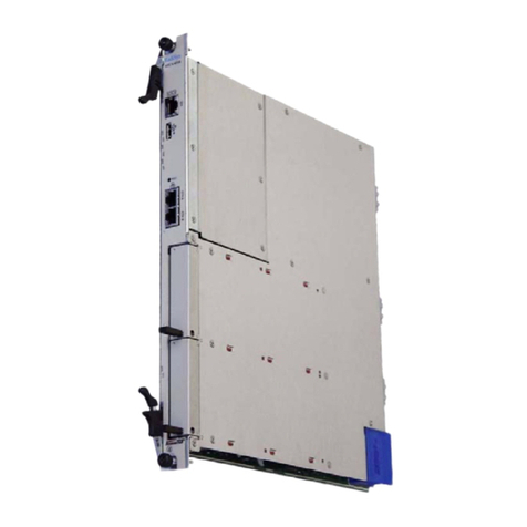
Aemulus AMOEBA 4200 Series User manual

Aemulus
DM482e
User Manual
Version 1.2, 10-2013

AEMULUS 1
Table of Contents
TABLE OF CONTENTS .............................................................................................................................. 1
SAFETY PRECAUTIONS............................................................................................................................ 2
A. GENERAL INFORMATION ................................................................................................................ 2
B. IDENTIFICATION AND DISCOURAGEMENT OF HAZARDOUS APPLICATIONS .................................................. 3
C. IDENTIFICATION OF AUTHORIZED PERSONNEL .................................................................................... 4
SECTION 1: QUICK START ........................................................................................................................ 6
1.1 PRODUCT START-UP CONFIGURATION..................................................................................................... 6
1.2 PRODUCT SOFTWARE &HARDWARE INSTALLATION ................................................................................... 7
SECTION 2: OPERATION ..........................................................................................................................8
2.1 FRONT PANEL CONNECTORS.................................................................................................................8
2.2 SOFT FRONT PANEL.......................................................................................................................... 12
2.2.1 General Functions ................................................................................................................................ 12
2.2.2 MIPI Functions ......................................................................................................................................17
2.3 REMOTE OPERATION......................................................................................................................... 20
SECTION 3: BRIEF TECHNICAL DESCRIPTION ......................................................................................... 21
3.1 BASIC OPERATION ............................................................................................................................ 21
3.1.1 Per Pin Parametric Measurement Unit (PPMU) Functions .................................................................... 21
3.1.2 Pin Electronics (PE) Functions .............................................................................................................. 23
3.1.3 Vector Engine Functions....................................................................................................................... 25
3.1.4 Triggers................................................................................................................................................ 27
3.1.5 MIPI ................................................................................................................................................... 28
3.2 SIGNAL CONNECTION ........................................................................................................................ 30
SECTION 4: MAINTENANCE ................................................................................................................... 31
4.1 CLEANING....................................................................................................................................... 31
4.2 CALIBRATION .................................................................................................................................. 31
4.3 SERVICING ...................................................................................................................................... 31
SECTION 5: WARRANTY......................................................................................................................... 32
SECTION 6: REVISION HISTORY............................................................................................................. 33
SECTION 7: CONTACT US....................................................................................................................... 34

DM482e User Manual
AEMULUS 2
Safety Precautions
A. General Information
Refer to the User Manual prepared by the manufacturer for proper usage of the
instrument.
If the product is used in a manner not specified, the protection provided by the
instrument warranty may be impaired.
Return the instrument to Aemulus for service and repair to ensure that safety
features are maintained.
The WARNING heading explains hazards that might
occur if an operating procedure, practice, or the like
that, if not correctly performed or adhered to might
result in personal injury or death. Always read the
associated information very carefully and make sure
the indicated information is met before performing the
indicated procedure.
The CAUTION heading in the user documentation
explains hazards that could damage the instrument.
Such damage may invalidate the warranty.
WARNING
CAUTION

DM482e User Manual
AEMULUS 3
B. Identification and Discouragement of Hazardous Applications
Main Power
Ensure that the mains power is turned off before plugging
or removing the PXI module into or from the chassis.
Make sure the power cord is plugged properly to the
chassis before applying power.
The chassis that carries the instrument has to be plugged
into a grounded (earthed) power outlet. By not doing so, it
will defeat the power cord safety ground feature.
Ensure that the power is removed from the product before
connecting/disconnecting the cables to the product
connectors.
Instrument Cables /
Connectors
Inspection of the connecting cable and test leads for
possible wear, cracks, or breaks must be done before each
use.
Make sure the cables used for the product are rated to the
specified voltage and current level.
Instrument Output
Extreme caution is to be practiced when a shock hazard is
present. Lethal voltage may be present on cable connector
jacks.
When power is applied to the circuit under test, do not
touch the product and test cables or test leads.
Do not touch the connector jacks or cables when the
output of the product is turned on.
If the DM482e has been in use, it might exceed safe handling
temperatures and cause burns. Allow some cooling time
before removing the DM482e from the chassis.
Hot Surface
WARNING
CAUTION
WARNING
WARNING

DM482e User Manual
AEMULUS 4
Operating
Temperature
The fan speed of the chassis that carries the instrument
has to be in HIGH speed to allow proper heat ventilation.
Make sure the product temperature is under 46˚C before
operating the product.
WARNING

DM482e User Manual
AEMULUS 5
C. Identification of Authorized Personnel
End user
Individual or group who is responsible for the use and maintenance
of the product, as well as being responsible for ensuring that the
product is operated within its specifications. Knowledge on
electrical safety procedures and proper use of the product are
prerequisite before operating the product.
Maintenance
personnel
Individual or group who is responsible for performing routine
procedures on the product to keep it operating properly. Any service
should only be done by qualified service personnel.
Service
personnel
Installation and service procedures may only be carried out by
properly trained service personnel. Knowledge on working with live
circuits, performing safe installations, and repairing the products are
prerequisite for this individual or group.

DM482e User Manual
AEMULUS 6
Section 1: Quick Start
1.1 Product Start-up Configuration
Each product is carefully inspected before it leaves the factory. Upon receipt and before
unpacking the product, please inspect the unit for any obvious damage that may occur during
shipment. If any damage is found, notify the instrument manufacturer immediately.
Please verify that the following items are included in the original packing of this product.
Contact the instrument manufacturer immediately if any of these items are found missing.
Reference / Drivers CD-ROM
The product is designed to be used in an indoor environment, an area with low condensation
and a temperature of between 23°C ± 10°C. Ensure that the area where the product is installed
is free from the presence of any explosive or flammable fumes or gases.
The product is shipped in materials that prevent static damage to the
module. The module should only be removed from the packaging in an
anti-static area ensuring that correct anti-static precautions are taken.
Store all modules in anti-static envelopes when not in use.
CAUTION

DM482e User Manual
AEMULUS 7
1.2 Product Software & Hardware Installation
Refer to installation guide.

DM482e User Manual
AEMULUS 8
Section 2: Operation
2.1 Front Panel Connectors
1 OUTPUT (VHDCI, 68-Position, Receptacle)
Figure 1: DM482e Front Panel

DM482e User Manual
AEMULUS 9
Pin
Signal Name (Primary)
Signal Name (MIPI)
Description
1
HV3
High Voltage Driver 3
2
HV4
High Voltage Driver 4
3
HV5
High Voltage Driver 5
4
-
-
5
-
-
6
-
-
7
PIN11_SH
Pin 11 Sense-High
8
PIN10_PIN11_L
VIO3_GND
Pin 10-11 Low
9
PIN11_FH
VIO3
Pin 11 Force-High
10
PIN8_PIN9_L
SCLK3_GND
Pin 8-9 Low
11
PIN9_FH
SCLK3
Pin 9 Force-High
12
PIN9_SH
Pin 9 Sense-High
13
PIN7_SH
Pin 7 Sense-High
14
PIN6_PIN7_L
SDATA2_GND
Pin 6-7 Low
15
PIN7_FH
SDATA2
Pin 7 Force-High
16
-
-
17
-
-
18
HV0
High Voltage Driver 0
19
HV1
High Voltage Driver 1
20
HV2
High Voltage Driver 2
21
EXT_TRIGIN0
External Trigger Input 0
22
GND
Ground
23
EXT_TRIGOUT0
External Trigger Output 0
24
GND
Ground
25
PIN5_SH
Pin 5 Sense-High
26
PIN4_PIN5_L
SDATA1_GND
Pin 4-5 Low
27
PIN5_FH
SDATA1
Pin 5 Force-High
28
PIN2_PIN3_L
VIO1_GND
Pin 2-3 Low
29
PIN3_FH
VIO1
Pin 3 Force-High
30
PIN3_SH
Pin 3 Sense-High
31
PIN1_FH
SDATA0
Pin 1 Force-High
32
PIN0_PIN1_L
SDATA0_GND
Pin 0-1 Low
33
PIN1_SH
Pin 1 Sense-High
34
-
-
Table 1: I/O Pin-out (Pins 1-34)

DM482e User Manual
AEMULUS 10
Pin
Signal Name (Primary)
Signal Name (MIPI)
Description
35
-
-
36
-
-
37
-
-
38
-
-
39
-
-
40
-
-
41
PIN10_SH
Pin 10 Sense-High
42
PIN10_PIN11_L
SDATA3_GND
Pin 10-11 Low
43
PIN10_FH
SDATA3
Pin 10 Force-High
44
PIN8_PIN9_L
VIO2_GND
Pin 8-9 Low
45
PIN8_FH
VIO2
Pin 8 Force-High
46
PIN8_SH
Pin 8 Sense-High
47
PIN6_SH
Pin 6 Sense-High
48
PIN6_PIN7_L
SCLK2_GND
Pin 6-7 Low
49
PIN6_FH
SCLK2
Pin 6 Force-High
50
GND
Ground
51
EXT_TRIGOUT1
External Trigger Output 1
52
GND
Ground
53
EXT_TRIGIN1
External Trigger Input 1
54
-
-
55
-
-
56
-
-
57
-
-
58
-
-
59
PIN4_SH
Pin 4 Sense-High
60
PIN4_PIN5_L
SCLK1_GND
Pin 4-5 Low
61
PIN4_FH
SCLK1
Pin 4 Force-High
62
PIN2_PIN3_L
VIO0_GND
Pin 2-3 Low
63
PIN2_FH
VIO0
Pin 2 Force-High
64
PIN2_SH
Pin 2 Sense-High
65
PIN0_FH
SCLK0
Pin 0 Force-High
66
PIN0_PIN1_L
SCLK0_GND
Pin 0-1 Low
67
PIN0_SH
Pin 0 Sense-High
68
-
-
Table 2: I/O Pin-out (Pins 35-68)

DM482e User Manual
AEMULUS 11
Signal Name
Description
HVx
High voltage driver capable of generating up to 13.5V.
PINx_FH
The I/O for a pin for all operating modes (PMU, VECTOR, DIO,
CLOCK, INVERTED_CLOCK). Refer to programming manual for
details.
PINx_SH
The remote sense line when operating in PMU mode.
PINx_PIN(x+1)_L
The ground reference level for a pin. 2 pins (PINx and PIN(x+1))
share the same reference level, and these 2 pins can be configured
as a differential pins.
EXT_TRIGOUTx
External trigger output from the module.
EXT_TRIGINx
External trigger input to the module.
SCLKx
SCLK pin for MIPI.
SDATAx
SDATA pin for MIPI.
VIOx
VIO pin for MIPI.
SCLKx_GND
SDATAx_GND
VIOx_GND
GND pin for MIPI. User should short all the GND pins together.
Table 3: Pin Function Description

DM482e User Manual
AEMULUS 12
2.2 Soft Front Panel
The soft front panel provides a graphical interface for operating the module. It is intended for
testing and diagnosing, for demonstration and training, and for basic operation of the module.
It represents most of the functions available in the instrument driver. It is not however a
comprehensive application suitable for measurements; for this, remote programming the
module.
2.2.1 General Functions
Figure 2: DM482e Soft Front Panel
1
2
3
4
7
6a
6
5
7a
8

DM482e User Manual
AEMULUS 13
Item
Description
1
Select the PXI address of the module. A list of addresses is shown for all detected
modules in the chassis.
2
Select the pin group.
3
Set the number of power line cycle, in second.
4
Set the frequency of the power line (50Hz or 60Hz).
3
Initialize the selected module. This includes opening a session to communicate with
the module, and then reset the module in its default state
5
Un-initialize the selected module. This includes closing the current communication
session to the module.
6
Per Pin Parametric Measurement Unit (PPMU) function:
a
Output Function
DC DVCI: Drive-Voltage Clamp-Current operation.
Continuous mode.
DC DICV: Drive-Current Clamp-Voltage operation.
Continuous mode.
b
Voltage Level
Voltage level
c
V Range
Range of the voltage level
d
Current Level
Current level (Current level setting is not required
in DVCI mode. “I Range” will decide the
compliance value)
e
I Range
Range of the current level
f
Sense
Select either Remote or Local sense connection
6a
Click the “Start” button for the selected pin to execute PMU commands. The
button will immediately turn to “Stop”. Press it to exit from PMU functions.
Following results are shown for each pin:
a. Voltage (V)
b. Current (A)
c. On-board temperature

DM482e User Manual
AEMULUS 14
7
Pin Electronics (PE):
Generic Setting:
a
DPIN Force
Sets the operation mode:
Mode
Description
VECTOR
Vector engine
DIO
General purpose I/O
CLOCK
Drive clock signal
INVERTED_CLOCK
Drive inverted clock
signal. This is when 2 pins
are selected as differential
outputs
b
DPIN Level
Set the levels for each pin.
c
DPIN On
Turn on/off the selected pin.
d
DPIN PE Attribute
Enable/disable active load and input termination
Vector:
a
DPIN Period
Specifies the timing set to be used, as well as its
period setting
b
DPIN VecLoad
Load the specified vector set in the vector file to
the module
c
DPIN RunVec
Run the specified vector set.
Clock/Invert Clock:
a
Configure Clock
Frequency
Configure the clock frequency when mode
“CLOCK” or “INVERTED_CLOCK” is selected.
DIO:
a
Set Pin Direction
Specifies the direction of the selected pin.
b
Set Port Direction
Specifies the direction of the selected pin group.

DM482e User Manual
AEMULUS 15
c
Drive/Read
Select Pin
Specifies the pin
Drive Pin Value
Specifies the logic level of the
pin to be driven
Drive Port Value
Enter the port value (in HEX) if
you want to drive to the whole
pin group
Select Function
Select from a list of available
DIO functions:
- Drive Pin
- Drive Port
- Read Pin
- Read Port
Click the “Start” button for the selected pin to execute the command.
The results for read functions for each pin will be displayed as either “H”
(logic high), “L” (logic low) or “Z” (undefined).
8
Display the actions taken in the background.
Table 4: Soft Front Panel Control

DM482e User Manual
AEMULUS 16
Quick steps to configure the module:
1. Select PXIe address of the targeted module from the drop-down list.
2. Select the targeted pin group. In this example, select “All Groups (PIN0-11)”.
3. Press “Initialize”.
4. The module is set to drive 1V and its current compliance is set to 25mA, in DVCI
mode.
5. Press “Start” to execute the commands. The button will immediate to “Stop”.
6. Both voltage and current are measured.
7. Press “Stop” to exit from PMU mode.
8. Press “Un-Initialize” to turn off the whole module.
Figure 3: PMU Operation

DM482e User Manual
AEMULUS 17
2.2.2 MIPI Functions
Figure 4: MIPI SFP
Item
Description
1
Tick to enable loop-back1operation
2
Display the address of the module connected. A list of addresses is shown for all
detected modules in the computer.
3
Set/ display the voltage supply of the module
4
Set/ display the frequency of the MIPI operation
5
Initialize or un-initialize the module
6
Data to be written into the module

DM482e User Manual
AEMULUS 18
7
Channel 0 control panel:
a
Start
Execute the operation
b
Command
The command to be sent to module for different
MIPI operation
c
Select Feature
Select either DM482e_MIPI_RFFE_WR,
DM482e_MIPI_RFFE_RD and
DM482e_MIPI_RFFE_RETRIEVE
d
Reset
Reset all ports to input, drive logic low. Reset all
internal registers
8
Channel 1 control panel:
a
Start
Execute the operation
b
Command
The command to be sent to module for different
MIPI operation
c
Select Feature
Select either DM482e_MIPI_RFFE_WR,
DM482e_MIPI_RFFE_RD and
DM482e_MIPI_RFFE_RETRIEVE
d
Reset
Reset all ports to input, drive logic low. Reset all
internal registers
9
Display the data after read operation, together with its corresponding parity check
bit.
10
Counter to display the number of data byte read
Table 5: MIPI Soft Front Panel Control
Note:
1. Loop-back –is an operation whereby the routing of signals or flows of items back to
their originating devices or facilities without intentional processing or modification.
This is used to test the transmission or transportation infrastructure.

DM482e User Manual
AEMULUS 19
Quick steps to configure the module:
1. Select PXIe address of the targeted module from the drop-down list.
2. Set the desired voltage level.
3. Set the desired frequency.
4. Press “Initialize”.
5. Set desired operation from the feature in channel 0 or channel 1. For example,
DM482e_MIPI_RFFE_WR.
6. Set the desired operation command, for example, 0x0202.
7. Set the data that should be written to the module at part (6). Refer to Figure 4.
8. Press “Start” to execute the command.
9. Press “Un-Initialize” to turn off the whole module.
Note:
Retrieve result and counter will be displayed after the operation of
DM482e_MIPI_RFFE_RETRIEVE.
This manual suits for next models
1
Table of contents
