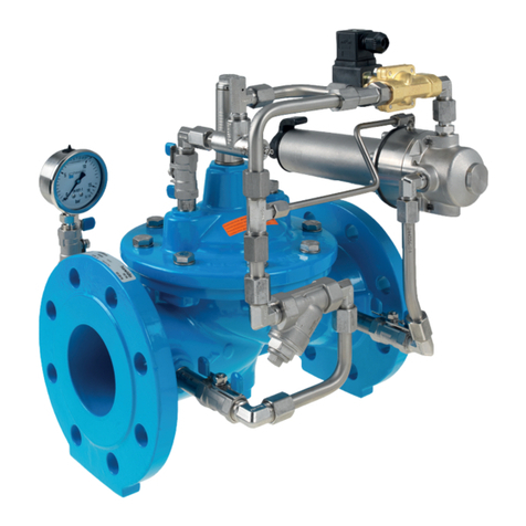
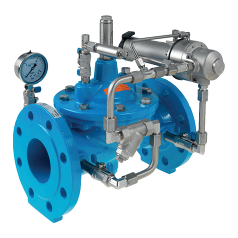
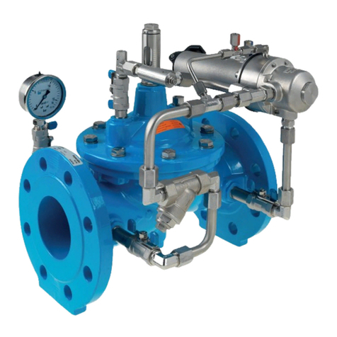
Hawle HAWIDO 1703 User manual

manual
On/Off valve for electrical remote control - closed without current®

HAWIDO - REGULATING VALVES
Instruction for
On/Off valve for electrical drive
Type 1703/04
ND40 - ND100
Keep this instruction manual at the location of the valve!

Example of rating plate
After the commissioning, enter the following data and make use of this additional information regarding the
valve type, pressure and flow ratios when consulting the manufacturer or the supplier or asking them questions:
Serial number: ................................................... DN ……………… PN: …………………..
Year of manufacture:...................................................
Anleitung Stand September 2018 - 1/plü Subject to technical changes!

-1-
CONTENTS
A. DESCRIPTION 2
1. FUNCTION 2
2. GENERAL SAFETY INSTRUCTIONS 2
3. RECOMMENDED INSTALLATION 3
B. COMMISSIONING 4
1. FUNCTIONAL DIAGRAM (1703) 4
2. PREPARATORY WORK 4
3. VENTING 4
4. SETTING-UP 5
5. SETTING THE REACTION SPEED 5
6. CHECKING FOR LEAKAGE 5
7. EMERGENCY MANUAL OPERATION 1703 5
C. FAULT FINDING 6
D. PUTTING OUT OF SERVICE AND MAINTENANCE 7
1. PUTTING OUT OF SERVICE 7
2. MAINTENANCE AND SERVICE 7
2.1 GENERAL INFORMATION 7
2.2 ANNUAL FUNCTIONAL CHECKS 7
2.3 4TO 5-YEAR MAINTENANCE 8
3. REPAIR KITS AND SPARE PARTS 9
3.1 BASE VALVE DN 40 TO DN 100 (DRAWING)10
3.2 MAIN VALVE (PARTS LIST)11
3.3 CONTROL LINE INDIVIDUAL PARTS AND ACCESSORIES 12
E. ANNEX 17
1. TORQUES 17
F. HAWLE IN EUROPE 18

-2-
A. Description
1. Function
The HAWIDO 1703 and HAWIDO 1704 are valve units with an electrical solenoid valve. The filling or
emptying of the control chamber of the main valve (1) are controlled by the electrical solenoid valve (5). The
pressure of its own medium therefore closes or opens the valve. Depending on the electrical solenoid valve
type (5), the valve can be positively or negatively controlled, i.e. the main valve (1) is normally-closed and
opens under voltage (HAWIDO 1703), or it is normally open and closes when under voltage (HAWIDO
1704).
The closing speed can be adjusted using the one-way flow restrictor (4).
Technical features:
Medium: Drinking water
Pressure stages: PN 10 (from DN 200 Standard)
PN16 (up to DN150 Standard)
PN25
Flanges: Connection dimensions according to DIN 1092 -2
Pressure gauge: EN 837-1; Accuracy class 1.6
Main valve material: EN-GJS-400-15
Temperature range: 2 –40 °C
2. General safety instructions
These instructions must be read through carefully and understood before starting the commissioning.
Damage to property and injuries to persons could occur as a result of improper installation, commissioning,
operation and maintenance.
The Hawle regulating valve (HAWIDO) has been designed for use in drinking and process water supplies.
Other application media only after consultation with the manufacturer.
The technical regulations (e.g. SVGW, ÖVGW, DVGW...) and codes of practice (e.g. VDE, VDI ...), laws and
standards are taken as a minimum standard, and must be adhered to and applied.
Work on electrical installations (e.g. installation of magnetic position switches, solenoid valves, etc.) may only
be carried out by personnel authorised for this work.
In principle, the responsibility for the layout, the installation position, the installation and the commissioning of
the fittings in the pipe work lies with the designer, the installation company and/or the operator. Design or
installation errors can adversely affect the safe operation of the regulating valve, and can represent a
significant risk. Please consult us in case of doubt.

-3-
3. Recommended installation
Before the installation of the fitting, the pipe lines must be carefully blown or flushed through to prevent any
foreign material, such as pieces of wood, stones etc., from entering the regulating valve.
The HAWIDO must be installed horizontally with the valve cover upwards (other models available on
request). We recommend that a gate valve and a dirt trap be fitted in front of the valve, as well as the
mounting of a gate valve at the outlet.
During maintenance, the valve must be decommissioned. A by-pass installation should be considered here
in order to ensure the supply.
Before the installation, check that no coarse foreign objects can penetrate into the HAWIDO.
Please contact us for other types of installation.
Installation note:
The water will be drained out of the valve chamber when the solenoid valve is switched (5). This water must
be led to the sewage system in accordance with local situation.

-4-
B. Commissioning
1. Functional diagram (1703)
Components
1 Main valve 1200
2 Ball valve
3 Filter
4 One-way flow restrictor (flow control valve)
Solenoid valve(drawn for Hawido Valve 1703,for
Hawido Valve 1704 solenoid valve no flow
without power)
6 Pressure gauge with ball valve
7 Valve opening limiter
electrical position indicator (optional)
2. Preparatory work
Before commissioning the valve, check that the gate valves on the inlet and outlet sides of the valve are
closed and that the flange connections have been correctly tightened and sealed.
Attention: Electrical work may only be carried out by qualified specialist personnel!
On the valve:
•The ball valve (2A) must be opened and the lock nut of the adjusting screw on the one-way flow
restrictor (4) must be loosened
•Unscrew the adjusting screw on the one-way flow restrictor (4) by approximately 10 turns. (The line
to the control chamber is open).
•Loosen the threaded pin in the central plug on the position indicator by a few turns.
•Slightly loosen a union of the control line at its highest point (approximately one turn).
•The solenoid valve (5)- must be free from voltage for the Hawido 1703 or- must have voltage for
the Hawido 1704
3. Venting
Procedure:
Loosen the threaded pin of the optical position indicator 2 –3 turns with a screwdriver (caution: Do not
completely unscrew the threaded pin!)
Slowly open the inlet gate valve on the inlet side until water flows into the valve. The valve fills with water
and the air escapes through the slightly open screw connection and the vent hole in the plug.
Once the valve venting procedure has caused all the air to be expelled from the control line, retighten the
plug screw and the loosened union. Check that all the fittings are properly sealed, and re-tighten if
necessary.
Slowly open the inlet gate valve completely.

-5-
Check: If the shut-off gate valve on the outlet side is slightly opened, the valve should close or remain
closed. Then close the shut-off gate valve again.
If the valve does not close, the commissioning procedure must be repeated from the previous chapter.
Particular care must then be taken to ensure that the upper valve chamber and control lines are properly
vented.
4. Setting-up
Procedure:
•Slowly and gradually open the shutoff gate valve on the outlet side.
•After opening the shut-off gate valve on the outlet side, completely open the shut-off gate valve on
the inlet side. The valve must remain closed.
•The solenoid valve (5)- is to have power applied to it (the main valve opens) on the Hawido 1703
or- is to have power removed from it on the Hawido 1704 (the main valve opens).
5. Setting the reaction speed
If the HAWIDO does not operate quietly, or if pressure shocks occur in the supply network, this can be
corrected by the corresponding adjustment of the one-way flow restrictor (4).
Procedure:
Loosen the locknut. Screw in the set screw clockwise with a screwdriver until the valve operates quietly.
Then retighten the locknut.
CautionThe setting screw must always remain at least 2 -3 turns open, otherwise the valve will not re-open
quickly enough after the closing sequence.
A special setting is necessary for very high inlet pressures.
6. Checking for leakage
HAWIDO valves are tested at the factory for both leakage and function before delivery. When checking for
leakage under operational conditions, particular attention must therefore be given to the seals of the flange
connections, the control line and the central plug screw on the valve cover. Where necessary, ensure the
seal by retightening the connections.
7. Emergency manual operation 1703
If the valve has to be opened manually during a power failure, proceed as described below:
•Slowly close the ball valve (2)
•Slightly loosen the plug (or corresponding accessories such as: opening limiter, valve position
indicator etc.) on the valve cover ➔the valve cover chamber drains itself and the valve opens.
•Put back into operation as described in the Commissioning chapter
Notes:

-6-
C. Fault finding
Symptoms
Possible cause
Action
Valve does not open
One-way flow restrictor blocked
Replace or unscrew the set
screw several times until the
valve functions properly
One-way flow restrictor closed
too far
Screw the set screw in and out
until the valve functions properly
Solenoid valve does not work
Check the function (electrical
work may only be carried out by
specialist personnel)
Valve does not close
One-way flow restrictor blocked
Replace, or screw the set screw
fully in and out several times
and then re-set
Filter in the control line blocked
Clean the filter
Air in the control line / upper
valve chamber
Vent
Foreign matter in the main valve
Carry out service and remove
any foreign matter
Diaphragm defective
Carry out a service.
Replace the diaphragm
Valve spindle jammed by
encrustation
Carry out service and remove
any encrustation
Solenoid valve does not work
Check the function (electrical
work may only be carried out by
specialist personnel)
Loud noise
Unfavourable operating
conditions
Slightly open or close the one-
way flow restrictor; Inform Field
Service
Wrong valve size
Have the correct valve size
calculated (contact Hawle)
Erratic operation
One-way flow restrictor
incorrectly set
Re-set as described in the
Setting the Reaction Speed
chapter
EWS coating damaged
Transportation damage,
installation damage
Repair with Hawle two-
component repair set for
coatings

-7-
D. Putting out of service and maintenance
1. Putting out of service
The operating valve must first be shut off hydraulically by proceeding as follows:
Attention: Electrical work may only be carried out by qualified specialist personnel!
•Slowly close the gate valves before and after the valve
In order to be able to carry out maintenance work on the valve, the solenoid valve must be disconnected
from the power. The electrical supply must be disconnected.
The valve has now been taken out of operation, and a service can be carried out.
2. Maintenance and service
2.1 General information
Through our many years of experience with diaphragm valves that are controlled by the flow medium, we
know that our HAWIDOs normally function trouble-free for many years. Regular maintenance is a
precondition for this, however.
Under normal operating conditions, the following should be carried out:
•The valve should be checked for correct operation once a year (functional check)
•The dirt trap upstream of the valve and the filter in the control line should be cleaned once a year
•The inner working components should be checked and worn parts be replaced every four to five
years (maintenance).
Under unusual operating conditions (e.g. with water that contains quantities of suspended matter, very high
pressure reduction, small flow rates etc.), the functional checks and the service work should be carried out
more frequently.
Maintenance sign:
xx stands for the respective year.
2.2 Annual functional checks
Cleaning the dirt trap in the main line
•Unscrew the lid
•Clean the filter with a brush or cloth etc., or replace it
•Install the filter and screw the lid back on
Cleaning the filter in the control line
•Unscrew the lid of the filter
•Clean the filter with a brush or cloth etc., or replace it
•Re-install the filter and screw the filter lid back on.

-8-
Checking the valve
•Remove the optical position indicator on the valve.
•Check that the valve spindle moves easily by raising and lowering it with the threaded rod. Increased
attention should be paid to this check, above all for valves with modified counter seats.
•Re-installation of the optical position indicator.
Putting back into service
•as described in the Commissioning paragraph
Functional check of the valve
•Valve 1703:
Solenoid valve (5) inactive (➔solenoid valve has flow) HAWIDO closes
Solenoid valve (5) has power (➔Solenoid valve closed) HAWIDO opens
•Valve 1704:
Solenoid valve (5) has power (➔solenoid valve has flow) HAWIDO closes
Solenoid valve (5) inactive (➔Solenoid valve closed) HAWIDO opens
2.3 4 to 5-year maintenance
Dirt trap (main line)
•Unscrew the lid
•Clean or replace the filter
•Install the filter and screw the lid back on
Filter (control line)
•Unscrew the lid of the filter
•Clean or replace the filter mesh
•Re-install the filter and screw the filter lid back on
Optical position indicator
•Dismount the optical position indicator.
•Clean the glass with a clean cloth
•Replace the seals (5)
•Reassembly; screw the double nipple and the screw plug together down to the stop
Base valve (see chapter: Repair kits and spare parts)
•Loosen the screw connections and remove the complete control line.
•Dismantle the optical position indicator or assembled accessories and replace the gaskets.
•Undo the screws of the valve cover and remove the cover.
•Visually inspect all inner components for wear, dirt and scaling
•Clean the inner components, the seat and the inner surfaces, including the cover
•Dismantle the spindle guide in the housing, flush the body interior
For valves DN 40 to DN 100 the spindle guide is dismantled from the inside. Here the thread of the
spindle guide and the base valve must be extremely clean. Grease the thread thoroughly (e.g.
Foodgrease Aqua, Art. no. 5292, see chapter "Control line individual parts and accessories”).
•Replace the diaphragm, the O-ring and, if necessary, the seat seal
•Grease the spindle guide area with a grease suitable for contact with food (e.g. Foodgrease Aqua).
Check the easy movement of the spindle.
•Reassemble the base valve (see table in the annex for torques). During the assembly, the easy
movement of the spindle must be checked several times by actuating the threaded rod

-9-
Functional check of the one-way flow restrictor
•Undo the locknut
•Screw in the throttle screw, and then unscrew it as far as it goes
•Screw in again a few turns. This process must be easy and meet little resistance
Putting back into operation and functional check
•In accordance with the Putting into Operation and Functional Check chapter and the previous
chapter
3. Repair kits and spare parts
Several replacement parts are required for the 4 or 5 - year service. These can be obtained as a repair kit
for:
•the main valve
•the control valve
•the control line
•the optical position indicator
The article numbers can be found in the part lists and the lists of spare parts.
Attention:
When ordering replacement parts, always specify the valve type, serial number and year of construction!
Important:
Replacement parts made of EPDM (diaphragms, seals) and NBR (O-rings) must be stored in a dark place,
protected from UV radiation!
Shelf-life when stored in the dark:
EPDM 8 years from date of manufacture
NBR 5 years from date of manufacture

-10-
3.1 Base valve DN 40 to DN 100 (drawing)
08.12.2011/plü

-11-
3.2 Main valve (Parts list)
Item.
Description
Material
Article number
DN 40
DN 50
DN 65
DN 80
DN 100
1
Body
GGG 40
1004 040 000
1004 050 000
1004 065 000
1004 080 000
1004 100 000
2
Valve cover
GGG 40
1014 050 000
1014 050 000
1014 065 000
1014 080 000
1014 100 000
3
Spindle guide cover
INOX
1024 900 000
1024 900 001
1024 900 002
1024 900 003
1024 900 004
4
Spindle
INOX
1026 050 000
1026 050 000
1026 065 000
1026 080 000
1026 100 000
5
Seat
INOX
*
*
*
*
*
6
Counter seat
INOX
1044 040 001
1044 050 001
1044 065 001
1044 080 001
1044 100 001
7
Seal
EPDM
1022 040 000
1022 050 000
1022 065 000
1022 080 000
1022 100 000
8
Seal carrier
INOX
1027 040 200
1027 050 200
1027 065 200
1027 080 200
1027 100 200
9
Diaphragm PN10/16
EPDM
1020 050 000
1020 050 000
1020 065 000
1020 080 000
1020 100 000
Diaphragm PN25
EPDM
1020 050 000
1020 050 000
1021 065 000
1021 080 000
1021 100 000
10
Pressure disc
INOX
1047 050 000
1047 050 000
1047 065 000
1047 080 000
1047 100 000
11
Nut
INOX
0007 710 080
0007 710 080
0007 712 080
0007 716 080
0007 716 080
12
Spring
INOX
1049 050 000
1049 050 000
1049 065 000
1049 080 000
1049 100 000
Spring for valves installed
upright position
INOX
1050 050 000
1050 050 000
1050 065 000
1050 080 000
1050 100 000
13
Spindle guide cover
INOX
1042 900 000
1042 900 000
1042 900 001
1042 900 002
1042 900 002
14
Hexagonal screw
INOX
0006 608 020
0006 608 020
0006 610 025
0006 610 025
0006 612 025
15
O-ring
NBR
0180 012 020
0180 012 020
0180 012 020
0180 016 020
0180 016 020
16
Washer
INOX
0008 208 000
0008 208 000
0008 210 000
0008 210 000
0008 212 000
17
GSK-sticker
1099 900 000
1099 900 000
1099 900 000
1099 900 000
1099 900 000
18
Maintenance sticker
9691 0xx 000
9691 0xx 000
9691 0xx 000
9691 0xx 000
9691 0xx 000
Main valve complete
PN10/16
1201 040 000
1201 050 000
1201 065 000
1201 080 000
1201 100 000
Main valve complete
PN25
--
--
1201 065 025
1201 080 025
1201 100 025
Repair kit for main valve
with stainless steel
connection, comprising
item 7, 9, 15, 18
PN10/16
1080 040 000
1080 050 000
1080 065 000
1080 080 000
1080 100 000
PN25
1080 040 000
1080 050 000
1081 065 000
1081 080 000
1081 100 000
° PN10
^ PN16
* not interchangeable
16.03.2018/plü

-12-
3.3 Control line individual parts and accessories
Master number
Designation
Picture
Size
further sizes possibly available
Art. number
0130
Compound seal
Stainless steel/NBR 3/8"
Stainless steel/NBR 1/2"
Stainless steel/NBR 3/4"
Stahl/NBR 1"
0130 012 000
0130 016 000
0130 025 000
0130 032 000
0273
Individual parts
Fitting connection (consisting of:
connector nut and clamping ring)
DN 12 stainless steel
connector nut only
0273 012 000
0274 xxx xxx
0275
Support sleeve
Stainless steel d4 –6
Stainless steel d12 –9
Stainless steel d12 –10
0275 006 004
0275 012 009
0275 012 010
0283
Clamping ring
d6 Stainless steel
d12 Stainless steel
d18 Stainless steel
d8 - 6 Stainless steel
0283 006 000
0283 012 000
0283 018 000
0283 008 006
0284
Orifice plate
(Old orifice plate
number
0281.
d12 Stainless steel Ø 0.6 mm
d12 Stainless steel Ø 0.9 mm
d12 Stainless steel Ø 1.2 mm
d12 Stainless steel Ø 1.5 mm
d12 Stainless steel Ø 1.9 mm
d12 Stainless steel Ø 2.4 mm
d12 Stainless steel Ø 3.1 mm
d18 Stainless steel Ø 3.5 mm
d18 Stainless steel Ø 4.0 mm
0284 006 000
0284 009 000
0284 012 000
0284 015 000
0284 019 000
0284 024 000
0284 031 000
0284 035 010
0284 040 010
0311
fitting
with screw-in nipple
d 12 - 3/8" Stainless steel
d 12 - 1/2" Stainless steel
d 6 - 1/8" Stainless steel
d 6 - 1/4" Stainless steel
d 6 - 3/8" Stainless steel
d18 –1/2" Stainless steel
0311 012 012
0311 012 016
0311 006 004
0311 006 008
0311 006 012
0311 018 016
0323
Straight fitting
d 6 Stainless steel
d 12 Stainless steel
0323 006 000
0323 012 000
0324
Straight socket
end fitting
d12 - 3/8"
0324 012 012
0351
Reduction
fitting
d6 –d12 stainless steel
0351 012 006
0361
Transition sleeve
d 10 - 3/8" Stainless steel
d 12 - 3/8" Stainless steel
d 12 - 1/2" Stainless steel
d 18 –1/2” Stainless steel
0361 010 012
0361 012 012
0361 012 016
0361 018 016
0371
Reduction nipple
IG d 12 –AG 3/8" Stainless steel
0371 012 012

-13-
0401
Sleeve
3/8" Stainless steel
1/2" Stainless steel
3/4" Stainless steel
1" Stainless steel
0401 012 000
0401 016 000
0401 025 000
0401 032 000
0411
Adjuster nipple
DN 6 - 1/8" Stainless steel
DN12 - 3/8" Stainless steel
0411 006 004
0411 012 012
0431
Screw-in elbow
DN 6 - 1/8" Stainless steel
DN6 - 1/4" Stainless steel
DN12 - 3/8" Stainless steel
DN18 - 1/2" Stainless steel
0431 006 004
0431 006 008
0431 012 012
0431 018 016
0431
Screw-in elbow with
vent
DN 123/8" Stainless steel
0431 012 013
0451
Angled fitting
DN6 Stainless steel
DN12 Stainless steel
DN18 Stainless steel
0451 006 000
0451 012 000
0451 018 000
0452
90° Adjuster elbow
DN12
0452 012 000
0455
Connector elbow
IG 3/8" Stainless steel
IG 1/2" Stainless steel
IG 3/4" Stainless steel
IG 1" Stainless steel
0455 012 000
0455 016 000
0455 025 000
0455 032 000
0456
Connector elbow
IG 3/8" - AG 3/8" Stainless steel
IG 1/2" - AG 1/2" Stainless steel
IG 3/4" - AG 3/4" Stainless steel
IG 1" –AG 1" Stainless steel
0456 012 000
0456 016 000
0456 025 000
0456 032 000
0461
T-piece
d6 Stainless steel
d12 Stainless steel
d12 - 6 - 12 Stainless steel
d18 stainless steel
0461 006 000
0461 012 000
0461 012 006
0461 018 000
0510
Plug
AG 3/8" conical stainless steel
AG 1/2" conical stainless steel
0510 012 000
0510 016 000
0511
Vent plug,
Lock screw
AG 1/2" Stainless steel
AG 3/4" Stainless steel
AG 1" stainless steel with hexagon
socket
0511 016 000
0511 025 000
0511 032 001
0520
hexagon double nipple
d 1/8" Stainless steel
d 1/4" Stainless steel
d 3/8" Stainless steel
d 1/2" Stainless steel
d 3/4" Stainless steel
0520 004 000
0520 008 000
0520 012 000
0520 016 000
0520 025 000
0541
Ball valve
DN 3/8" stainless steel
DN 1/2" stainless steel
DN 3/4" stainless steel
0541 012 001
0541 016 000
0541 016 010

-14-
0545
Stainless steel dirt filter
Stainless steel Y-filter IG 3/8"
Individual parts:
Stainless steel dirt filter
Plug, complete for Y-filter, stainless
steel
Large seal for Y-filter, POM
Small O-ring for plug
Stainless steel Y-filter IG 1/2"
0545 112 002
0545 900 051
0545 112 010
0545 112 011
0545 112 012
0545 116 000
0549
Flow control valve
& check valve
DN 3/8" Check valve brass nickel-plated
Stainless steel IG 3/8" type B d 12 with
long spindle
0549 000 002
0549 000 005
0570
Non-return valve
3/8" brass (max. 40 bar)
1/2" brass (max. 40 bar)
0570 012 045
0570 016 045
0600
Pressure gauge
AG 3/8" 0 - 6 bar
AG 3/8" 0 - 10 bar
AG 3/8" 0 - 16 bar
AG 3/8" 0 - 25 bar
AG 3/8" 0 - 40 bar
AG 3/8" 0 - 60 bar
0600 012 006
0600 012 010
0600 012 016
0600 012 025
0600 012 040
0600 012 060
0610
Solenoid valves
Solenoid valve, normally open2/2–way
valve (for 1795/96)
122K84
Solenoid valve, normally closed
2/2 way valve (for 1795/96)
E121K04
Solenoid valve, normally open
3/2 way valve (for 1703 to DN 100
1603, 1706 PN 16 all nominal sizes)
132K04
Solenoid valve normally closed
3/2 way valve (for 1704 to DN 100,
1604
E131K04
Solenoid valve normally open
2/2 way valve (for 1704 from DN 125
1304, 1404, 1504)
(old: E322 H73 06)
Solenoid valve normally closed
2/2 way valve, with manual override
(For 1703 from DN 125,1303, 1403,
1503, 1706 PN 25 from DN 125)
(old: E321 (H13)
Solenoid valve universal
3/2 way valve (for 1706 PN 25
to DN 100)
*********************************************
Replacement part. Diaphragm, for MV
type
0610 510 001 and 0610 510 002
Replacement part set for MV type 0610
510 001
Consisting of: Diaphragm,
Armature guide tube, armature and
seals
0610 122 084
0610 121 004
0610 132 004
0610 131 004
0610 510 002
0610 510 001
0610 133 005
**********************
0610 590 001
0610 590 002

-15-
0620, 0621
Coils
AC coils with
voltage indication
DC coils with
voltage indication
0620 xxx xxx
0621 xxx xxx
0630
Appliance socket
Appliance socket
for electromagnet
0630 000 000
0653
Connector modules
Connector modules for solenoid valves
Type LBV 24 DC 8S, incl. 2m cable
Connector modules for solenoid valves
Type LBV
IN: 48-230VAC/DC
OUT: 48VDC
incl. 2m cable 3-wire
(Only to be used for 48VDC coils)
0653 024 008
0653 230 000
0670
Overcut
AG 3/8" IG 1/8" Stainless steel
AG 3/8" IG 1/4" Stainless steel
AG 1/2" IG 3/8" Stainless steel
AG 3/4" IG 3/8" Stainless steel
AG 1" IG 1/8" Stainless steel
AG 1" IG 1/2" Stainless steel
0670 012 004
0670 012 008
0670 016 012
0670 025 012
0670 032 012
0670 032 016
0671
Sleeve nipple reduced
IG 1/2" AG 3/8"
IG 1" AG 3/8"
IG 1" AG 1/2"
IG 1" AG 3/4"
0671 016 012
0671 032 012
0671 032 016
0671 032 025
0680
Barrel nipple
AG 3/8" L = 30 mm Stainless steel
AG 3/8" L = 40 mm Stainless steel
AG 3/8" L = 50 mm Stainless steel
AG 3/8" L = 60 mm Stainless steel
AG 3/8" L = 70 mm Stainless steel
AG 3/8" L = 80 mm Stainless steel
AG 3/8" L = 110 mm Stainless steel
AG 1/2" L = xxx mm Stainless steel
0680 012 030
0680 012 040
0680 012 050
0680 012 060
0680 012 070
0680 012 080
0680 012 110
0680 016 xxx
0690
Adapting nipple
AG 3/8" - 1/8"
AG 3/8" - 1/4"
AG 1/2" - 3/8"
AG 3/4" - 3/8"
AG 1" - 3/8"
AG 1" –1/2"
0690 012 004
0690 012 008
0690 016 012
0690 025 012
0690 032 012
0690 032 016
0711
T-fitting
IG 3/8" level Stainless steel
IG 1/2" level Stainless steel
IG 3/4" level Stainless steel
IG 1" level Stainless steel
0711 012 000
0711 016 000
0711 025 000
0711 032 000
0730
Seamless tube
d6 x 1mm Stainless steel
d12 x 1.5 mm Stainless steel
d15 x 1.5 mm Stainless steel
d18 x 1.5 mm Stainless steel
0730 006 010
0730 012 015
0730 015 015
0730 018 015

-16-
1188
Rep. Set
Control line
From serial number14252 (January
2003)
DN40 to 100
DN125 to 300
From approx. serial number 25915
(June 2014,
Filter type B (0545 112 002)
DN40 bis 100
DN125 bis 200
1188 065 100
1188 125 300
1188 000 000
1188 000 001
SA.0
PA-tube
Polyamide tube OD 6 mm, ID 4 mm
Polyamide tube OD 12 mm, ID 9 mm
SA.0 000 060
SA.0 000 290
Tools and accessories
1199
Spindle lifting tool
M5
M6
1199 000 000
1199 000 010
1199
Spanner for sealing
plate
Spanner for assembling
and dismantling the
sealing plate from the DRV pilot
valve
1199 000 020
1199
Socket spanner
attachment
Socket spanner attachment for flow
control valve
1199 000 030
1199
Socket spanner
Socket spanner for flow control valve
1199 000 040
5292
Grease
Foodgrease Aqua
Tube with 175g
5292 000 020
02.02.2018/plü

-17-
E. Annex
1. Torques
When assembling the base valve and the control valves all bolts are checked with a torque spanner
according to the following list. Lightly grease the bolts before assembling!
Nominal size
Hex bolt
Strength
Tightening torque
Base valves
DN
M
class 1)
Target
Max.2 )
40 - 50
M 8
A4/80
22 Nm
25 Nm
65 - 80
M 10
47 Nm
50 Nm
100
M 12
84 Nm
87 Nm
125 - 150
M 16
172 Nm
216 Nm
200
M 20
285 Nm
423 Nm
250
M 20
285 Nm
423 Nm
300
M 20
380 Nm
423 Nm
Control valves
Type
Socket
Strength
Tightening torque
M
class 1)
Target
Max.
DRV / DAV
M 6
A2 / A4 / 70
8 Nm
8.5 Nm
MBV / RBS
Control
Hex bolt
Strength
Tightening torque
valve
M
class
Target
Max.
NAZ
M 6
A2 / A4 / 70
8 Nm
8.5 Nm
(Not for new applications)
Base valves
Nominal size
Hex bolt
Strength
Tightening torque
DN
M
class 1)
Target
Max.
40 - 50
M 8
A2/70
17 Nm
19 Nm
65
M 10
33 Nm
36 Nm
80
M 10
40 Nm
40 Nm
100
M 12
70 Nm
72 Nm
125 - 150
M 16
172 Nm
172 Nm
200
M 20
280 Nm
285 Nm
250
M 20
280 Nm
285 Nm
300
M 20
235 Nm
240 Nm
Attention: 1) = Note designation on screw head A2 –70 or A4 –80!
2) = Maximum permitted torque according to strength analysis
Bolts according to SN EN ISO 4014 and SN EN ISO 4017
As at: FO 0065, Rev. 12 / 19.12.2017
This manual suits for next models
1
Table of contents
Other Hawle Control Unit manuals
Popular Control Unit manuals by other brands

YASKAWA
YASKAWA Motoman MLX200 Software Operation Users Manual

KMC Controls
KMC Controls VEB-53 Series installation guide

Speck
Speck UL50/1000Dr operating instructions

Varian
Varian ProStar 500 Driver manual

Siemens
Siemens QAW850 operating instructions

Victaulic
Victaulic FireLock 758-LPA Series Installation, Maintenance, & Testing Manual