AEQ TLE-02D User manual

A.E.Q., S.A. the manufacturer of this equipment, is “Registered
Company” number ER-080/1/96 conforming to the AENOR UNE EN - ISO - 9001 quality
assurance standard.
TLE-02D
Portable Digital Communications Unit
USER’S MANUAL
ED. 08/99
USO RESTRITO

TLE-02D
Portable Digital Communications Unit
2
INDEX
1. DESCRIPTION OF THE EQUIPMENT
1.1. BASIC DESIGN CONCEPTS
1.2. SPECIFICATIONS
1.3. FUNCTIONAL DIAGRAM
2. POWER SUPPLY
2.1. GENERAL
2.1.1. UNIT POWER SUPPLY
2.1.2. SWITCHING ON
3. INSTALLATION AND WIRING
3.1. DESCRIPTION OF THE FRONT PANEL
3.2. DESCRIPTION OF THE REAR PANEL
4. DESCRIPTION OF CONTROLS
4.1. VISUALISATION AND USER INTERFACE CONTROL SECTION
4.2. DIALLING SECTION
4.3. MONITOR AND LEVEL CONTROL SECTION
5. ISDN MODE USER INTERFACE
5.1. START-UP
5.2. ACCESS TO THE ‘PHONE BOOK AND RECALL
5.3. ACCESS TO CODIFICATION CHANGING
5.4. MANUAL DIALLING
5.5. CALL GENERATION
5.6. CONNECTION ESTABLISHED
5.6.1. DATA CHANNEL
5.6.2. VUMETER MODE
5.7. GENERATION OF DTMF TONES FOR REMOTE CONTROL
6. TLE MODE USER INTERFACE
6.1. START-UP
6.2. EXTENDED OPERATION MODE
6.3. ACCESS TO THE ‘PHONE BOOK AND RECALL
6.4. CALL GENERATION
6.5. GENERATION OF DTMF TONES FOR REMOTE CONTROL
7. UPGRADING THE INTERNAL SOFTWARE (FIRMWARE UPGRADE)
7.1. SYSTEM DESCRIPTION
7.2. REQUIREMENTS OF THE PC USED FOR UPGRADING
7.3. CONNECTIONS FOR CONTROL COMPUTER
7.4. FIRMWARE UPGRADING
8. TECHNICAL SPECIFICATIONS
APPENDIX 1: GUIDE TO RAPID USE
1. TO ESTABLISH COMMUNICATION
1.1. CTN MODE
1.2. ISDN MODE
2. EQUIPMENT USE ONCE COMMUNICATION IS ESTABLISHED
APPENDIX 2: AEQ WARRANTY
USO RESTRITO

TLE-02D
Portable Digital Communications Unit
3
1. DESCRIPTION OF THE EQUIPMENT
1.1. Basic design concepts
The AEQ TLE-02D Portable Communications Unit is designed in a compact format offering
easy to use unique features such as an audiocodec, a digital telephone hybrid, a frequency
extender and a portable mixer.
The AEQ TLE-02D is the only equipment in the market offering such a high integration in a
single portable unit.
Exclusive design, equipped with a Double Power Supply System through standard dry cells or
external powering, allowing a fantastic operation autonomy.
Dial-pad with selectable Pulse/DTMF tones.
Auxiliary Output with level control.
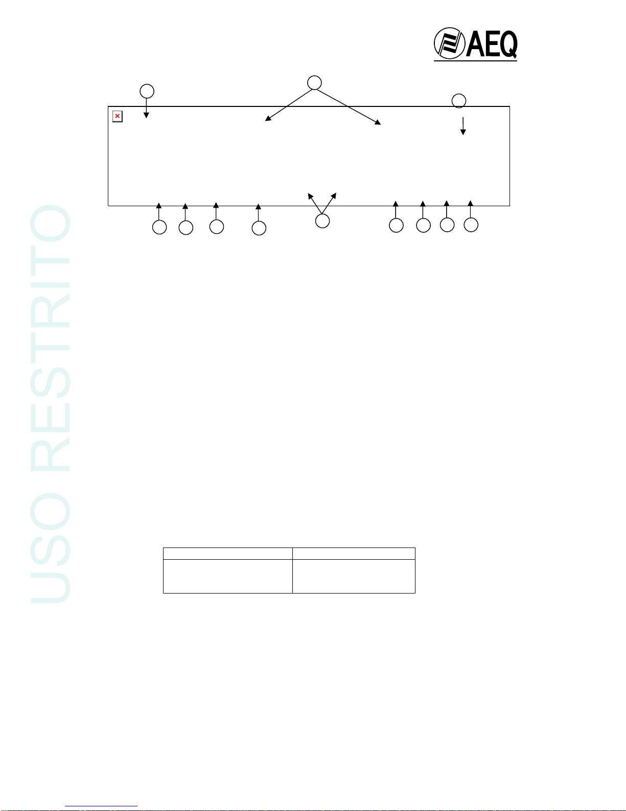
RJ-45 connector for ISDN lines and RJ-11 for Analogue Telephone Lines.
Four Wires always available.
Selection of routed signals to Auxiliary Output.
The AEQ TLE-02D - the ideal portable unit for remote broadcasting operation - will connect
several On-Air commentators in the field to your studio by digital or analogue telephone lines.
The advanced technology in the AEQ TLE-02D will provide you with a cost-effective remote
capability, simple to install and easy to operate.
1.2. Specifications:
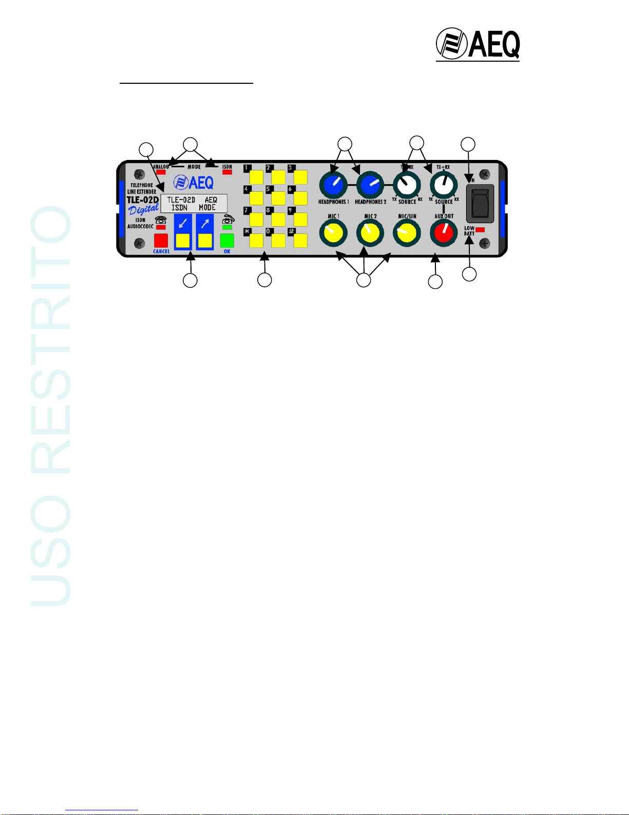
•Two microphone and one micro/line inputs, with COMBO connectors for XLR3 and Jack ¼’’.
•Independent analogue mix level control for each input channel.
•The mixer signal is treated with an analogue compressor/limiter to avoid clipping in the
digital stages.
•Two stereo headphone outputs, with independent level and mix controls.
•Monitoring Mix control over headphones and Auxiliary Output Control allowing to monitor
only Send (TX), only Return (RX) or a mix of them to any relationship.
•Monitoring of the Auxiliary Input, with trim level.
•Dialling with Sub-Adressing Capability (when using ISDN (where this is available).
•4 Wire Input/Output Interface
•Backlit LCD display. Indication of status, dial numbers, phonebook entries and menu
options.
•Acoustic signalling of the incoming calls either in ISDN or Analogue Telephone Lines.
•Alphanumeric Phonebook with up to 256 entries.
•Menu configuration using only two buttons
•Software up-grade available through Flash-RAM technology.
•Transmission modes:
ISDN Mode: Available audio coding algorithms:
•G.722, Statistical framing 64 Kbps. Bandwidth: 20Hz – 7KHz
•G.722 H221/H242 framing 64 Kbps. (including Auxiliary Data Channel transport),
Bandwidth: 20Hz – 7KHz
•G.711/64 Kbps: A and µ Laws, for connection with standard telephone numbers
•E-ISDN Protocol
Analogue Telephone Line Mode:
•Digital Hybrid with Frecuency Extender and echo cancellation (64dB rejection), dial
pad for tone or pulse.
•Bandwidth:
-Without Extender: 300Hz - 3300Hz
-With Frequency Extender: 50Hz - 3050Hz
USO RESTRITO

TLE-02D
Portable Digital Communications Unit
4
1.3. Functional diagram
Schematic functional diagram of the Audio Codec.
USO RESTRITO

TLE-02D
Portable Digital Communications Unit
5
The signal generated in each of the three channels (2 microphone and 1 micro/line) pass to the
mixer circuit and then, after passing through a limiter, are sent to the A/D converter on one
hand, and to the foldback circuit on the other.
The foldback circuits allow the continuous adjustment from only Program go to Return signal,
i.e. any mix between both.
The channel levels are adjusted by the Mic1, Mic2 and Mic/Lin potentiometer.
The signal, once it has been limited, passes to the analogue-digital converter and is processed
in the DSP, that is programmed for transmission by ISDN or CTN (Commuted Telephone
Network).
In the former case, the signals reach the TA (terminal adapter) which is controlled by the
communication controller, this accepts user instructions entered through the keyboard with this
information being shown on the alphanumeric display.
In the latter case, the signals are sent to the CTN telephone socket through the D/A converter
and analog hybrid instead of the ISDN adapters (TA).
In both cases, a return signal travels in the reverse direction from the communication interface
to the DSP, from where it passes to the D/A converter that generates the Program return signal.
This signal may be heard in the commentator’s headphones.
The Unit in turn has a data and control port, to send and receive auxiliary data and for
equipment configuration and upgrading.
USO RESTRITO

TLE-02D
Portable Digital Communications Unit
6
2. POWER SUPPLY
2.1. General
The power supply connector (1) is found on the rear panel of the unit.
2.1.1. Unit power supply
The AEQ TLE-02D can be powered by standard batteries or an external source.
If an external power supply is to be used it must be connected to the 12V DC-INPUT (1).
The power supply unit supplied with the equipment, or an alternative unit capable of delivering
the correct voltage and current, must be used.
The cable supplied with the power supply unit is fitted with a standard pin plug, which is
lockable to prevent accidental disconnection.
If a standard alkaline battery power supply is to be used:
8 standard 1.5V AA (LR6) alkaline batteries must be fitted to the AEQ TLE-02D, this will allow
approximately 1h30m autonomy at 100% yield. AEQ recommends DURACELL batteries.
2.1.2. Switching on
Before connecting the power supply ensure the on/off switch is in the OFF position.
Once the lockable plug is correctly connected to the unit, it should be connected to the network
supply.
Turn the power supply switch to ON. If all the previous steps have been correctly followed, the
display will illuminate, indicating that the equipment is receiving power.
1
USO RESTRITO

TLE-02D
Portable Digital Communications Unit
7
3. INSTALLATION AND WIRING
To clarify the installation and wiring process it is necessary to be familiar with the connectors
and configurable elements.
3.1 Description of the front panel
The following controls are mounted on the front and Control panels; these are explained later:
(1) The backlit LCD display
(2) The numeric keyboard
(3) The Multifunction and Audiocodec Control Keys
(4) Mic and Mic/Lin channel Input level controls
(5) Headphones Output level controls
(6) Auxiliary Output Level control
(7) Auxiliary Output and Heaphones Output Mix controls
(8) ISDN-CTN indicators
(9) Power supply switch (ON)
(10) Low Battery indicator
3
1
4
7 9
6
2
5
10
8
USO RESTRITO

TLE-02D
Portable Digital Communications Unit
8
3.2. Description of the rear panel
A series of combo XLR3-Jacks (1 and 2) are found on the front panel, one is connected to each
channel of each input. This type of connector allows the connection of male XLR3 or ¼” male
telephone type jack plugs, therefore admitting balanced or asymmetric signals.
The headphone outputs (4) are provided with ¼” stereo telephone jacks.
The Mic/Tape channel possesses a micro/line level selector switch (3).
The numbered elements and their use are described in the following selection
(1) Microphone Inputs 1 and 2
(2) Micro/Line Input
(3) Mic/Line switch
(4) Heaphones Output 1 and 2
(5) RS232 Data channel and Control port. Sub-D 9 Female
(6) RJ45 ISDN line connector
(7) RJ11 Analogue Telephone Line (CTN) connector
(8) Mode selector switch ISDN (ISDN) – Analogue Telephone Line (CTN)
(9) Dial mode selector switch Pulse – DTMF Tones in CTN mode
(10) 4 Wire interface
(11) Auxiliary Input trim level
(12) Power supply connector (DC-INPUT)
Microphone Inputs 1 and 2
The microphones are normally supplied with the appropriate connectors for direct connection to
the Audiocodec. The connector wiring is shown below:
XLR connectors ¼” Jack connectors
1: ground sleeve: ground
2: microphone V+ tip: microphone V+
3: microphone V- ring: microphone V-
Mic/Line Input
A cable with either a male XLR3 or ¼” stereo Jack must be used. The connector wiring is the
same as that for the microphone inputs.
Mic/Line switch
To select microphone input level, the switch is set to the rest position (switch button out), and to
select line input level, the switch is set to the activated position (switch button in).
4
12 5
1 97
10 2 3 86
11
USO RESTRITO

TLE-02D
Portable Digital Communications Unit
9
Heaphones Outputs
A standard TRS ¼” headphone output jack is fitted. The connector wiring is shown below:
¼” Jack connectors
Tip: Left earpiece
Ring: Right earpiece
Sleeve: Common ground
Connections for Control and Data port (RS232 port)
The unit has a female DB 9 chassis mounted connector for configuration and transmission of
auxiliary data in conjunction with an external computer communicating through RS 232 protocol
(a cable fitted with male connector must therefore be used). The active contacts are:
TX 2
RX 3
GND 5
A Pin-to-Pin Male-Female cable must be used and connected to the PC serial port.
For details of the PC serial communication port, consult the user manual supplied with the
computer.
RJ45 chassis connector wiring
The RJ 45 connector connects the terminal adapter, which is included in the
equipment, with the ISDN access point (Network terminal). This connector wiring
is standard according to the following diagram.
For connection to the ISDN line socket the cable supplied with the equipment, or
similar, must be used.
Cable Number Connections
1
2
3 ---------- Tx V+
4 ---------- Rx V -
5 ---------- Rx V+
6 ---------- Tx V -
7
8
RJ11 chassis connector wiring:
Connection to the telephone line is by 4 contact RJ11 type connector. The telephone line must
be connected according to the standard for RJ11 connectors (using the two centre contacts, 2
and 3).
For connection to the telephone line socket the cable supplied with the equipment, or similar,
must be used.
Frontal View
USO RESTRITO

TLE-02D
Portable Digital Communications Unit
10
Selector Switch for ISDN-Analogue Telephone Line Mode (MODE SELECT ISDN/ANALOG
TELEPHONE LINE):
This selects the required line type (ISDN - CTN).
Important: To change the line type selection the equipment must be switched-off and restarted
with the new configuration.
.
Dial mode selector switch Pulse – DTMF Tones in CTN mode:
This switch selects the dial mode by Pulse or by DTMF Tones, allowing generating DTMF tones
to effect remote control operations in mode CTN.
4 Wire Interface
Full Bandwidth (20Hz-20KHz). Whether the unit is used as an Audiocodec on ISDN or as a
portable Telephone Hybrid on CTN, the transformed balanced 4W input/output is always
available, being operative to use it simultaneously with any of the two modes.
The return input has a level adjustment (TRIM) and it is permanently routed to the headset
outputs. Therefore it can be used for the connection of other Auxiliary signals that could be
required to be monitored by the reporters, such as Guides, Cue, P.A., International Sound, etc.
The Aux. out has also a mix control for the send and return signals (SOURCE), in this way
increasing the possibilities of the equipment which can be used as per the following examples:
- As a conventional 4W circuit, or a pre-mixer, setting the associated control knob
SOURCE in TX position.
- As a recording output, setting the associated control knob SOURCE in an intermediate
position TX/RX. This way, both program and return signals are available at the Output.
- As an auxiliary output of the digital hybrid, setting the associated control knob
SOURCE in RX positions. This way the unit can be connected to other equipment or to
a loudspeaker in order to use the hybrid as a hands-free telephone.
4 Wire Interface Auxiliary Input level adjustment:
The 4 wire interface auxiliary input level can be adjusted with the Trimmer (LEVEL TRIM)
located next to the interface.
Power supply:
Power is delivered to the Unit by the supplied AC-Adaptor or another suitable power supply,
through the DC-INPUT connector.
DC Voltage 12 V.
Polarity: V+ : centre pin; V- : exterior
Current: 0.52 A. @ 12V
Connector: Standard cylindrical DC, 2 mm internal, 6 mm external
Power consumption: Approx. 6W.
If the unit is to be powered by batteries, 8 standard 1.5V AA (LR6) alkaline batteries must be
fitted. The batteries are inserted through the top of the unit. AEQ recommends DURACELL
batteries. Correct polarity must be observed. Batteries must be inserted as indicated in the
diagram in the battery compartment.
USO RESTRITO

TLE-02D
Portable Digital Communications Unit
11
4. DESCRIPTION OF CONTROLS
Control Panel
From the operational point of view, the control panel is divided into three sections:
•Visualisation and User Interface Control Section
•Dialling Section
•Monitor and level control section
4.1. Visualisation and User Interface Control Section
The status of the AEQ TLE-02D Audiocodec
(connection, codification, number dialled, etc.), as well
as the configuration, can be visualised on the Display
(2 lines X 16 characters). Access is gained to the
various configuration menus, dialling, telephone book,
etc. by using the four pushbuttons (Two Multifunction
Keys, OK, CANCEL) situated under the visual Display.
The upper line of the Display is for user information and
the lower line shows the function associated with each
of the two Multifunction keys. The use of the
Multifunction keys is explained in section 5 and 6 “User
Interface”.
4.2. Dialling Section
The dialling section consists of the numeric keyboard,
for entering the number to be dialled.
Fig. 4.1 Position of the control panel elements.
USO RESTRITO

TLE-02D
Portable Digital Communications Unit
12
4.3. Monitor and level control section
This section of the control panel is comprised of
eight potentiometers. These allow the
AEQ TLE-02D to adjust the mix levels of each
input (two microphone and one mic/line) with
independent level adjustment for each, and with
level adjustment for each output: two headphones
and one auxiliary output, therefore the adjustment
of the mix heard in the outputs is independent for
both headphones and the auxiliary output: Send,
Return, or any intermediate mix between the two.
USO RESTRITO

TLE-02D
Portable Digital Communications Unit
13
5. ISDN MODE USER INTERFACE
ISDN Mode User Interface Flow diagram:
USO RESTRITO

TLE-02D
Portable Digital Communications Unit
14
5.1. Start-Up:
The following window appears when the equipment is started:
Two seconds later, an information windows appears with the firmware versions downloaded to
the different modules (Microcontroller, DSP and TA) of the AEQ TLE-02D, besides a PAUSE
label. When the yellow key next to that label is pressed, it is sustituted with the label CONT,
keeping the information of the versions until CONT is pressed.
If you have not pressed PAUSE, two seconds later the unit passes to the stand-by window
(initial window):
In the initial window (1), the default codification mode selected for the establishment of the
circuit connection appears on the top line of the display.
The function associated with each of the multifunction keys appears on the bottom line of the
display.
“P-BOOK” “CHCOD”
In this situation the user can perform three operations:
1.- Activating “P-BOOK” (Telephone Book) displays the ‘phone book which is included
in the unit.
2.- Activating “CHCOD” (CHANGE CODIFICATION) accesses the window which allows
the mode of connection codification to be changed
3.- Finally, if the numerical keyboard is used in the stand-by state, the manual number
composition window appears and the user can manually enter a telephone number and
make a call.
The following describes the use of the above functions:
5.2. Access to the Phone Book and Recall
On activating “P-BOOK” the following window appears:
The last number dialled is shown on the top line. . If the ‘phone book is entered from start-up no
number is displayed, if any calls have been made, the last number dialled will be seen, window
(2).
Recall is effected using the key. The “UP” and “DOWN” keys are used to enter the ‘phone
book and pass through the 256 Phone Book entries.
(1)
(2)
ISDN G722 STAT
P-BOOK CHCOD
LAST NUMBER DIALLED
UP DOWN
TLE-02D AEQ
ISDN MODE (0)
MCUV1.10 TAV 1.04
DSPV1.01 PAUSA
USO RESTRITO

TLE-02D
Portable Digital Communications Unit
15
The first entry stored in the ‘phone book’s non-volatile RAM memory appears on the upper line
of the display.
Each ‘phone book entry has three fields:
Position number field: A001......A256, to designate the position of the entry in the ‘phone
book.
LABEL field: maximum 10 characters, to give a name to the entry.
NUMBER field: maximum 16 digits, to save the telephone number.
If the ‘phone book registry is empty only the registry number is displayed, and the label field
does not appear.
The user can select the desired entry by using the “UP” and “DOWN” keys to pass through the
256 available registers. Using the “DOWN” key will display entry number 1, and using the “UP”
key will display entry number 256. By pressing “UP” or “DOWN” for more than two seconds
allows a fast search whithin the P-Book entries in the selected direction (up or down).
Pressing “CANCEL” will return to the stand-by window (1).
The “OK” key validates the entry selected by the user and passes to window (3):
The key is pressed to establish the connection.
Activating “NUMBER” displays the telephone number associated with this ‘phone book entry
(3’).
Pressing “CANCEL” will return to the previous window (3).
The “EDIT” key summons the edit/modify window for the selected entry.
First, the number associated to the entry in question is edited (4).
The telephone number associated to the selected ‘phone book registry appears on the top line
of the display. If the said registry is empty, the top line of the display will be blank (the cursor
position is marked by the corresponding display position blinking. Initially the cursor is displaced
to first position on the display).
The numerical keyboard enters the number directly onto the top line of the display and
automatically advances the cursor.
The “⇐“ and “⇒“ keys move the cursor backwards (and erases the digit above the cursor) or
forwards respectively to modify the numbers which have been introduced.
Finally, the “OK” key validates the number and passes to the label edit window (5).
If the registry is empty, the registry number is shown on the top line of the display and the
cursor blinks in the first modifiable position, with the “LABEL” field remaining blank.
(5)
(4)
A001 LABEL
<DEL <= =>
(3)
A001 LABEL
EDIT NUMBER
TELEPHONE NUMBER
TELEPHONE NUMBER
<= =>
USO RESTRITO

TLE-02D
Portable Digital Communications Unit
16
The characters which form the label are selected using the “⇐⇒“ key to pass through the table
containing all the alphabetical and special characters such as blank space (“ “) and hyphen (“-“).
(“A, B,...,Z, -, ). When starting from an empty registry, pressing “⇐⇒“ will show “A“.
The numerical keyboard is used to introduce the “*” or the “#” and numerical characters into the
label.
It is only necessary to pause for one second after pressing “⇐⇒“ or the numeric keyboard to
select the desired character and pass to the next position in the label. The cursor automatically
advances to the next position.
The “<DEL” key deletes the character and moves the cursor one step backwards.
Finally, in window (5), the label associated with the selected ‘phone book register is definitively
validated using the “OK” key, and is stored in non-volatile RAM memory and the stand-by
window (1) appears.
5.3. Access to codification changing
Activating the “CHCOD” key when in the stand-by state (1), opens the codification change
window (6):
The user can view the different codification modes available by using the “UP” and “DOWN”
keys to pass through the table:
64 Modes:
ISDN G711 A-LAW ........................A Law.
ISDN G711 µ-LAW ........................µLaw.
ISDN G722 STAT ..........................G722 Statistical.
ISDN G722 H221 ...........................G722 H221/H242
If the “DOWN” key is pressed in the state represented by (Fig. 6) the legend “ISDN G722
H221“ will appear on the top line of the display, and if “UP” is pressed the message “ISDN
G711 µ-LAW” will appear. Next to the label of each mode, it appears a blinking quotation mark.
Pressing the “CANCEL” key will return to the initial window without modifying the current
codification setting.
Pressing “OK” validates the selected codification mode, the quotation mark stops blinking and
the stand-by window (1’) will appear with the new codification mode being shown on the top line
of the display. For example, if “ISDN G711 µ-LAW” is selected, the following will be seen on
returning to the stand-by state:
5.4. Manual dialling
If the numeric keyboard located on the front of the unit is used when in stand-by status, the
dialling window will open (7):
The number will appear on the top line of the display as it is entered.
(1’)
(7)
ISDN G722 STAT?
UP DOWN
ISDN G711 µ-LAW
P-BOOK CHCOD
9______
<DEL
USO RESTRITO

TLE-02D
Portable Digital Communications Unit
17
Using the “<DEL” key will delete the last digit entered.
Pressing the key will initiate the call to the number that has been manually entered.
The “CANCEL” key may be used to return to the stand-by window (1) if it is not desired to
establish communication at this time.
5.5. Call generation
Activating the key in any of the windows represented by Fig. (3) and (7), initiates the call
generation process, which results in the display of a release of call, or successful connection
message.
When communication is initiated, window (8) will appear:
If the communication continues successfully and connection is established the connection
established window (9) will open.
This window is detailed in the following section.
If on the other hand the connection cannot be established, the user will be informed of the
reason for the failure.
The following call release messages are issued by the equipment:
i) ERROR: An internal error has occurred in the call generation process.
ii) NO ISDN AVAILABLE: An attempt has been made to establish communication when
there is no ISDN line available.
iii) DESTINATION BUSY: The remote terminal is occupied.
iv) NO ANSWER: The remote terminal has not responded to the incoming call.
v) CALL REJECTED: The network has rejected the call, this includes all the remaining
possible causes of release.
vi) CALL NOT CONNECTED: The waiting time set for the unit to establish connection with
a remote terminal has expired.
The equipment will return to the stand-by window (1) following the emission of any of these
release messages.
5.6. Connection established
The following message will appear in the display after window (8) if the connection is
established:
and the stablished-connection window (9) will appear one second later:
SYNC./NO SYNC.: Connection is established an synchronised / not synchronised
CODIF: Opens the codification window
(9)
(8)
(9)
CALL IN PROGRESS
PRG CON. SYNC.
CODIF VU
PRG CON. SYNC.
CODIF VU
CALL CONNECTED
USO RESTRITO

TLE-02D
Portable Digital Communications Unit
18
VU: Opens the VU-meter mode window..
When using G722 H221/242 codification mode, the “CODIF” key is changed to “DATCHN”,
since this mode allows the establishment of a data channel.
The “DATCHN” key opens the window for the establishment of a data channel.
The key is used to terminate the connection in the stablished-connection window (9) and
the initial stand-by window (1) will return.
The same happens when the remote terminal terminates the connection.
5.6.1. Data channel:
This is a transparent bi-directional point-to-point 1200 baud channel.
For the channel to operate correctly, the transmission configuration should be set to:
–1200 bauds
–No parity
–8 data bits
–1 stop bit
The data channel can be established in G722 H221/H242 codification mode, the only
codification mode in the equipment that allows the establishment of an auxiliary data channel.
The establishment of data channels is not permissible in the remaining modes as listed in the
chart in section 5.3.
If mode G722 H221/H242 is being used, the “DATCHN” appears instead of the “CODIF”
key. Activating the “DATCHN” key opens window (10):
Pressing the “Rx” and “Tx” keys activates (On) or deactivates (Off) the transmission
(Tx) or reception (Rx) of the data channel.
Pressing the “CANCEL” key will return to window (9).
5.6.2. VU-meter mode:
Pressing the VU key in window (9) will open the VU-meter window (11):
The output levels from the Output channel are represented by ”▓“ characters. If the output
signal level is below –22dBu the ”▓” character will not appear in the display. Each “▓“ character
represents a step of 2 dBu. The “)” represents 0 dBu level. Levels above “)” are shown as
+2,+4,+6dBu and finally the character ”O” which represents Program signal saturation level
(+18dBu). To avoid saturation, it is advisable not to exceed the recommended input levels..
“CANCEL” is used to return to window (9).
5.7. Generation of DTMF tones for remote control.
It is possible to generate and send DTMF tones to line to effect remote control operations when
operating in ISDN mode and in connection established status (9). It is necessary to press the
corresponding digit on the keyboard. The audio Program is cut during tone generation.
(11)
(10)
TXoff RXoff
TX RX
▓▓▓▓▓▓▓▓▓▓▓▓▓▓ ƒ)ƒƒƒO
USO RESTRITO

TLE-02D
Portable Digital Communications Unit
19
6. CTN MODE USER INTERFACE
CTN Mode User Interface Flow diagram
USO RESTRITO

TLE-02D
Portable Digital Communications Unit
20
6.1. Start-up:
When the equipment is switched-on and CTN mode is selected by the switch on the rear panel,
the following window will be displayed:
and two seconds later the analogue stand-by window (1) will appear:
When the equipment is switched-on NORMAL operation is selected by default. Pressing the
“EXTEN” key changes the operational mode to EXTENDED. The stand-by window changes to
show the new “NORM” key (1’).
6.2. Extended operation mode.
Typical telephone circuits have a limited band width between 300 and 4000 Hz. Unfortunately,
the major part of voice energy is in frequencies below 300 Hz, and is lost during transmission
over telephone lines. Telephone audio signals have their characteristic sound, the loss of voice
body being the most notable, for this reason.
The extended operation mode allows the transmission of frequencies between 50 and 300 Hz
through telephone lines. To achieve this, the signal is subjected to a 250 Hz frequency shift
before being sent, thereby improving the low frequency band quality of the signal received at
the expense of the highest band. The bandwidth transmitted is, therefore, between 50 and
3750 Hz. The 250 Hz lost in the highest frequencies are not very significant given the
logarithmic nature of audio frequency response.
The frequency shift is performed by encoding the audio signal before it is sent to the telephone
line. The suitably equipped receiver decodes the signal, that is to say, the frequency shift is
reversed. The decoded signal contains the original band (50-3750 HZ) without suffering any
type of degradation. In this way, a voice signal with improved clarity and depth is achieved,
including during those communications that take place under the worst conditions.
Switching between Extended and Normal mode is performed using the “EXTEN/NORM” key
during ANALOG stand-by mode (1).
6.3. Access to the Phone Book and Recall:
The ‘phone book is shared by both the equipment’s working modes (ISDN and CTN).
Access is identical to that described in ISDN mode section 5.2.
(1)
(1’)
TLE-02D AEQ
ANALOG MODE
ANALOG TELEPHONE
EXTEN P-BOOK
ANALOG TELEPHONE
NORM P-BOOK
USO RESTRITO
Table of contents