Aerial-51 ALT-512 User manual

PART-1: INTRODUCTION
1.1
16-MAY-2019 ALT- 512 (Preliminary) User Manual Ver. 1.0a
Aerial-51 ALT-512
(Preliminary)
User Manual
Ver. 1.0a

PART-1: INTRODUCTION
1.2
16-MAY-2019 ALT- 512 (Preliminary) User Manual Ver. 1.0a
CONTENT
PART 1: INTRODUCTION . . . . . . . . . . . . . . . . . . . . . . . 1.3
PART 2: PANELS AND CONTROLS . . . . . . . . . . . . . . . . 2.1
PART 3: BUTTON OPERATION . . . . . . . . . . . . . . . . . . . 3.1
PART 4: OPERATION . . . . . . . . . . . . . . . . . . . . . . . . . . . 4.1
PART 5: MENU ITEMS . . . . . . . . . . . . . . . . . . . . . . . . . . 5.1

PART-1: INTRODUCTION
1.3
16-MAY-2019 ALT- 512 (Preliminary) User Manual Ver. 1.0a
IMPORTANT MESSAGE
OPERATING an amateur radio transmitter requires a license in every
country of the world! Using the ALT-512 without a license is punishable
by law in every country of the world!
INTRODUCTION
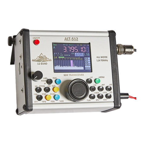
The ALT-512 is a 12 band, all mode
SDR transceiver with a 2.4in. (6cm)
color TFT display. It has a built-in
sound card and all the capabilities of
a modern transceiver. It is easy to
operate and does not require a
computer to operate CW, SSB, FM, or
AM modes.
A computer is required for working
DIGI modes, but nothing else! A
single USB-2 cable to the computer is
all that is necessary. The rest is done
in the computer. No external sound
card, interfaces, boxes, or cables are
required
The ALT-512 has rich capabilities for
operating digital modes, including
Noise Reduction (NR) and Noise
Blanker (NB). It has 4 front panel
adjustable DSP filters (RX & TX) that
are user-definable in bandwidth
and frequency response
The ALT 512 has a 48 kHz panoramic
bansdscope and waterfall that are
continuosly active on RX and TX;
(only one may be displayed at a
time). This gives the operator a view
of the activity within +/- 24kHz of the
display frequency, helping to find an
unoccupied frequency on crowded
bands.
The ALT 512 comes with a hand
microphone for voice modes, and has
adjustable mic gain, speech com-
pressor, and echo chamber. It also
has an automatic Iambic CW keyer
with A/B modes. It displays output
power in Watts, SWR, ALC level and
CW speed, either numerically, or as
bar graph. It has a PTT jack with
sequencer for controlling an External
linear amplifier.
The ALT 512’s 2 VFO’smemorize
the last used information on each
band. The two VFO’s may be used on
the same band in SPLIT mode, or on
different bands, enabling Cross-Band
operation.
The ALT-512’s CAT control system
emulates the full TS-2000 command
set. It connects to the computer with
a single USB cable, uses the FTDI
chipset, and has its own audio
codec.
- - - - --- - - - - - --- - -
BEFORE BEGINNING OPERATION
PLEASE, READ THIS ENTIRE
MANUAL CAREFULLY
THIS RADIO REQUIRES:
•A valid amateur radio license
for HF and VHF
•A regulated power supply (or
battery) for [nominal] 12.6
volts d.c., but not less than
10.5 and not more than 13.6
volts, at 2.5A.
•A 50 Ohms (nominal) antenna
for each band to be used.
•Optional:
•Stereo headphones: 4 to 32
ohms, or ext. speaker 4-8
ohms (passive- not active)
•Straight Key or Paddle

PART-1: INTRODUCTION
1.4
16-MAY-2019 ALT- 512 (Preliminary) User Manual Ver. 1.0a
TECHNICAL DATA
GENERAL INFORMATION
Technology
SDR
Direct Digital Conversion
Frequency/ Bands
High-Performance
HF Ham Bands:
1.8 MHz to 70.50 MHz
(not General Coverage)
(see Receive-Only)
Transceive:
•160, 80, 60, 40, 30, 20,
17, 15, 12, 10, 6 , 4m
Receive-Only:
•100 to 1800 kHz
•27.000 to 28.000 MHz
•US: 4m –receive only
Transverters option:
144 and 432 MHz with 28
MHz IF –drive level 150mW;
TRUE FREQUENCY READOUT
on 2m and 70cm by setting
the frequency shift in menu
#36 (Shift VFO)
MODES
CW, USB, LSB, DIGI, AM, FM
CAT: USB2 (FTDI)
Digital Modes
FT4, FТ8, JT65, PSK, RTTY,
SSTV
Proprietary Audio Codec
Output Power
5 to10 W typical
(varies by band and mode)
High-SWR Protection
(foldback power)
Antenna Impedance
50 ohms (nominal)
BNC connector
DC Power Supply
From 10.5V to 13.6Vd.c.
(recommended 12.6V)
Fuse: 3.15A, 250V, slow blow
Consumption
RX: average 350mA
TX: up to 2 .5A
Frequency stability
±3 ppm
0 to 50 C°
Memory
100 channels (0-99)
Stores: Frequency, Mode,
VFO (A/B) and more
Speaker
0.5 W
built-in
Panoramic bandscope
and waterfall
Active on RX and TX / Adjustable Color Display
Enclosure size
12.8 x 10.7 x 5.5 cm
(w.o. knobs and connectors)
Working size
14.7 x 10.7 x 7 cm
(with knobs and connectors)
Weight
580 grams (20.5 oz.)
(without microphone)

PART-1: INTRODUCTION
1.5
16-MAY-2019 ALT- 512 (Preliminary) User Manual Ver. 1.0a
TRANSMITTER
POWER
5 to 10 Watts - average, band-
dependent; front panel or
software menu adjustment
Automatic SWR Protection
Metering on Transmit
Selectable: Output Power, SWR,
Mic Gain, ALC
Display: either bar graph
or digital (numeric)
Metering DC voltage
Numeric or Digital
VOX SSB
Adjustable Gain and Delay
Speech Compressor
Adjustable in Menu
“CMR”in menu
Reverb
Adjustable in Menu
“ECHO” in menu
TX Мute /Monitor/
Monitor for voice modes (SSB, AM, FM) and DIGI
CW Key Type
Selectable: Paddle or Straight Key
Built-in Auto Keyer
Iambic A/B
Default: В
Auto Key Settings
Speed - MENU NR.04/
Dot/Dash Ratio - MENU NR.05
MENU selectable
CW VOX
Delay Adjustable
From 100ms to 5 Seconds
in 100ms steps.
DIGI Level Adjustment
Adjusts Audio Level on Transmit
in DIGI Mode
Front panel adjustment
Ext. Amp Control
(PTT)
Controls external amplifier with
hang-delay in steps of 50ms.
Open Collector Switching
TX DSP filters
Two modes of operation
Default or User Definable
•SSB TX filters
Default : 2.800 kHz
Bandwidth: 750Hz to 4.15kHz
Passband: 250Hz to 4.4kHz
(adjustable)
•CW TX filters
Default: 100 Hz
Fixed: 100Hz
•AM TX filters
Default: 5.590 kHz
2kHz to 10kHz
•FM TX filters
Default: 9.600 kHz
2kHz to 10kHz
DIGI TX filters
Default: 4.000 kHz
Fixed: 4kHZ
TX Bandscope or
Waterfall
Monitors Transmited Signal
Push PAN button briefly to
toggle the monitor mode
between Bandscope or
Waterfall
SOUND CARD FOR
DIGI MODE
AUDIO CODEC PCM2902/4
Implemented for all
operating systems:
WIN, LINUX, & MAC. No
additional driver required.

PART-1: INTRODUCTION
1.6
16-MAY-2019 ALT- 512 (Preliminary) User Manual Ver. 1.0a
RECEIVER
Technology
SDR
(CPU digital delay 21 ms)
Direct Digital Conversion
Sensitivity
0.2 Uv/13dB s/n
Preamp ON
Preamplifier
+20 dB
Attenuator
-12 dB
Preliminary
Filtering
9 BPF and 8 LPF
160m, 80m, 60+40m, 30+20m,
17+15m, 12+10m, 6, 4m,
+100 to 1800kHz
Consumption
Average 350mA
Bandscope and
Waterfall
Bandwidth: 48kHz
Toggles with[PAN] Button
Front Panel or Menu Adjustments
DSP RX filters
4 DSP Filters per Mode
See Below
SSB Filters
4 DSP Filters per Mode
Fil-1, Fil-2, Fil-3, Fil-4
(User Adjustable)
200Hz to 4.4 kHz
CW Filters
20 Hz to 1kHz
AM Filters
2kHz to 12kHz
FM Filters
2kHz to 12 kHz
Digital Modes
Filters
4 Fixed Bandwith
Fil-1: 4Khz / 250 - 4250Hz
Fil-2: 2KHz / 250 - 2250 Hz
Fil-3: 1KHz / 500 - 1500Hz
Fil-4: 500hz / 500 - 1000Hz
Noise Reduction
(NR)
Front Panel or Menu Adjustable
Noise Blanker
(NB)
Front Panel or Menu Adjustable
NOTCH FILTER
(NF)
Active only in SSB mode.
Front panel or Menu Adjustable
S-Meter
Bar Graph in S-Units
+ Digital Display
CW Mode
CW or CWR (Reverse)
Selectable with Mode Button
SQUELCH
Front Panel Button
Type: ‘SSB/AM’ or ‘FM’;
Adjustable Level from 0 to 100
IF –Virtual
Intermediate
Frequency
When ON, DSP is operating
normal; When OFF–the
radio operates as a normal
Direct Conversion Receiver.
Software MENU Selection
Must always be ON.
Sound Card for
DIGI MODE
AUDIO CODEC PCM2904
Implemented for all operating
systems: WIN, LINUX, & MAC.
No additional driver required.

PART-1: INTRODUCTION
1.7
16-MAY-2019 ALT- 512 (Preliminary) User Manual Ver. 1.0a
Accessories
ALT-512 (In the box):
DC power cable: red (+) and black
(-) with built-in fuse and barrel
connector (2.5mm x 5mm).
Microphone: electret type , power
thru mic cable (tip). To use dynamic
microphone, insert 350nF to 470nF
capacitor between the dynamic mic
capsule and the mic wire.
This Manual (Preliminary V.1.0)
CAT cable: standard USB2 cable
with “type A” connector on both ends.
Not Pictured:
•2mm Allen Wrench
•2.5mm Allen Wrench
•Spare Fuse

PART-2: PANELS AND CONTROLS OVERVIEW
16-MAY-2019 ALT- 512 (Preliminary) User Manual Ver. 1.0a
FRONT PANEL CONTROLS
NOTE:
•‘Push’= momentary push.
•‘Long-Push’= 1 second or
longer
(1) [VFO]
•Normal Operation: Used for
changing the frequency of the
VFO’s.
•In Menu Mode: Used for
changing the value within the
sub-menus.
(2) AF GAIN CONTROL
(3) [ON/OFF]: Used to turn the
radio On and Off.
(4) [UP]
•Normal Operation: Push to
change band to next higher
band.
•In Menu Mode: Used to step
through the sub-menus. Push
[UP] changes to next higher
sub-menu.
(5) [DN] (Down)
•Normal Operation: Push to
change band to next lower band.
•In Menu Mode: Used to step
through the sub-menus. Push
[DN]changes to next lower sub-
menu.
2.1

PART-2: PANELS AND CONTROLS OVERVIEW
16-MAY-2019 ALT- 512 (Preliminary) User Manual Ver. 1.0a
(6) [MEM]/[TUN]: (Tune)
•[MEM]: Push activates memory
operations.
•[TUN]: Long-Push generates a
reduced-power signal for the
purpose of tuning an external
ATU. Turn OFF with Push.
(7) [MENU]: Push Toggles the
Software Menu ON or OFF.
(8) [RIT]: Receive Incremental
Tuning
•IN RX Mode: Push Toggles RIT
ON or OFF
•IN TX Mode: Push Toggles XIT
ON/OFF
(9) [VFO]/[SPL]: VFO Selection /
Split
•[VFO]: Push to toggle between
VFO-A and VFO-B
•[SPL]: Long-Push enables
Split-VFO Operation.
Disable SPLIT with another
Long-Push
(10) [NR]: Toggles Noise Reduction
ON or OFF
(11) [VDE]/[SQ]:
[VDE]: VOX DEFINE (GAIN);
Lon- Push activates the VOX
GAIN adjustment menu.
[SQ]: Squelch: 2 adjustable
modes: ‘FM’or ‘SSB/AM’.
•Push toggles Squelch ON/OFF
•Adjust level with [VFO] knob.
(12) [PAN]: Push Toggles display
between Bandscope/Waterfall.
Long-Push activates menus for
adjustment.
(13) [FILT]: (Filter); Push selects
DSP filters (Fil-1 to FIL-4).
Long-Push activates filter
adjustment menu.
(14) [MOD] (Mode) / [VOX]
•[MOD]: Push toggles through
modes: CW/CWR/DIG/ AM/FM/
USB/LSB, etc.
•[VOX]: Long Push toggles
VOX ON and OFF
2.2

PART-2: PANELS AND CONTROLS OVERVIEW
16-MAY-2019 ALT- 512 (Preliminary) User Manual Ver. 1.0a
(15) [AGC]/[POW]/[IF]
•[AGC]: Long-Push activates
the AGC time-constant
adjustment.
•[POW]: (Power) When in
transmit mode (PTT keyed)
Push to enter the TX Power
Adjustment menu.
•[IF]: Push Toggles the
Virtual Intermediate
Frequency ON or OFF.
Should always be ON!
(16) [NB]: Noise Blanker; Push
toggles the NB ON or OFF;
Long-Push activates the NB
adjustment menu.
(17) [STEP]/[FDE]
•[STEP]: Push toggles through
the different tuning rates of the
VFO.
•[FDE]: Function Defining
Executive –Push to step
through items of sub-menus.
======================
(18) [NF]/[PITCH]
•[NF]: Notch Filter (SSB Mode
Only);
oIn RX Mode: Push to
toggle Notch Filter ON or
OFF. Long-Push activates
NF adjustment menu.
oIn TX mode, Push to
toggle Echo ON/OFF.
Long-Push activates Echo
adjustment menu.
•[PITCH]: (In CW Mode Only);
Push to activate menu for
adjustment of Offset Frequency.
(19) [PRE]/[ATT]/[RFG]
(Preamp/Attenuator/RF Gain)
•[PRE]/[ATT]: Push to toggle
through activating Preamp,
Attenuator, Both OFF.
•[RFG]: Long-Push to activate
RF Gain adjustment. Adjust
with [VFO]. Push to exit.
======================
2.3

PART-2: PANELS AND CONTROLS OVERVIEW
16-MAY-2019 ALT- 512 (Preliminary) User Manual Ver. 1.0a
DISPLAY
TFT 2.4 INCH color display with 66,000 colors.
In the picture below, all possible RX functions are shown active for the
purpose of explanation. You will not see all features active at once during
normal operation.
NOTE: The screen is shown here in RECEIVE mode.
During TRANSMIT mode, the menu on the right is replaced
with a smaller menu showing only functions applicable to TX.
During TX, the contents of the S-Meter line is replaced by the TX
Meter. showing (one at a time, selectable) PWR/SWR/ALC/MIC.
2.4

PART-2: PANELS AND CONTROLS OVERVIEW
16-MAY-2019 ALT- 512 (Preliminary) User Manual Ver. 1.0a
Left Side Panel
KEY: The ALT-512 can operate with a
straight key or paddle. The connection
is via a 3.5 mm stereo phone-jack –as
described below:
MIC: The ALT-512 is supplied with an
electret (condenser) hand-microphone
with a 3.5mm stereo phone-plug (Pin-
out below). To us another type of mic
(i.e., dynamic), insert a 270-470nf
capacitor in series with the MIC+ line.
MON (+SIDETONE): Adjust
monitor level or sidetone level to the
desired level using a tiny screwdriver
inserted through the small MON-hole.
CAUTION: ROTATE CAREFULLY!
HEADPHONES: The ALT-512 can be
used with any stereo headphones
from 4 to 64 ohms impedance (lower
impedance works better). A (passive)
external speaker may also be
connected here. It accepts a 3.5mm
stereo Phone-Plug.
CAT (+built-in audio codec and
SOUND CARD): The ALT-512 can
interface to most common types of
computers via aUSB2 cable with Type-
A plugs on both ends. It has an FTDI
chipset and uses its own audio codеc
(PCM2904), thus no additional driver is
required!
Its САТ Interface is fully compatible
with the KENWOOD TS-2000’s CAT
Command set.
COM PORT SETTINGS:
•(RIG Type: TS-2000)
•Baud rate: 9600
•Data bits : 8
•Parity: NONE
•Stop bits: 1
2.5

PART-2: PANELS AND CONTROLS OVERVIEW
16-MAY-2019 ALT- 512 (Preliminary) User Manual Ver. 1.0a
Right Side Panel
DC 12.6V: power source via standard
coaxial (barrel) connector.
SIZE: 2.5mm x 7mm.
ANT: BNC Female Jack; 50 Ohms
(nominal) impedance.
PTT: RCA Phono Jack; Open-Drain
MOS transistor switch, 3A max.
Delay: 50ms. Use to switch external
linear amplifier’s T/R relay.
SPKR: Internal 8 Ohms, 0,5 watt
loudspeaker; The speaker is switched
off automatically when you connect
headphones or an external speaker to
the radio. ====================
2.6

PART-3: DETAILED BUTTON OPERATION
3.1
16-MAY-2019 ALT- 512 (Preliminary) User Manual Ver. 1.0a
DETAILED BUTTON DESCRIPTION
This section of the manual goes into much more detail about the operation of
each of the front panel buttons.
ALL features adjustable here are also adjustable within the Software Menu.
Details about the adjustments and settings within each feature are described in
the “MENU” section of this manual.
Due to the small size of the radio and large number of features, it was not
possible to include all of the labels on the front panel. Some of the features may
be considered “hidden features.” They were not hidden for any special reason,
there was simply not enough space on the panel to write all of the names.
Hidden Features (i.e., “XIT”) will be shown in the text below like this: {XIT}.
Normal Features will be shown like this: [RIT]
Push = Momentary (short) push of the button.
Long-Push = Push the button for 1 second or more.
NOTE: The “[VFO]”name is used twice in this document; once to designate
the VFO knob and again to designate the button for selecting VFO-A or VFO-B.
When adjusting values within a menu and it says change with [VFO], it is
referring to the VFO knob, not the button.

PART-3: DETAILED BUTTON OPERATION
3.2
16-MAY-2019 ALT- 512 (Preliminary) User Manual Ver. 1.0a
1. [VFO]: TUNING / Multi-Functional Knob
•During normal operation, the [VFO] knob is used for changing
frequency. Clockwise (CW) rotation increases the frequency; Counter-
Clockwise (CCW) rotation decreases the frequency.
•When in MENU mode, [VFO] is used for changing/selecting values
within some of the menu items.
2. [AF]: Audio Gain Control (Volume Control); Rotating the volume control
CW increases the audio gain; rotating CCW decreases the audio gain.
3. [ON/OFF] Button: Powers the radio ON or OFF.
4. [UP]:
•During normal operation, each push of the [UP] button changes to the
next higher band.
•In “MENU Mode”pushing [UP]changes to the next higher menu item.
When it reaches the top, pushing it again returns to Menu #0.
5. [DN]: DOWN
•During normal operation, each push of the [DN]button changes to the
next lower band.
•In “MENU Mode” pushing [DN]changes to the next lower menu item.
When it reaches Menu #0, pushing again returns to the top, Menu #39.
6. [MEM]/[TUN]: Memory / Tune
Storing to Memory:
•Push [МЕМ]; the next free memory slot is displayed. Push [DN] to copy
VFO and other data (i.e., mode) to ‘that’ memory location, then Push
[МЕМ]again to store the data.
•Or, select a different memory location with the [VFO] knob; rotating CW
moves to the next higher memory slot; rotating CCW moves to the next
lower memory slot. After selecting a memory slot, Push [DN] and then
Push [MEM] to store the data in that slot.
Recalling from Memory:
•Push [МЕМ], then select memory location with the [VFO] knob (as
described above), then Push [UP]and then Push [МЕМ]to upload the
memory contents to the VFO.

PART-3: DETAILED BUTTON OPERATION
3.3
16-MAY-2019 ALT- 512 (Preliminary) User Manual Ver. 1.0a
[TUN] (Tune): A Long-Push of [TUN] places the radio in transmit,
generating a signal with about 1/3 of maximum power. Use this feature to
tune an antenna tuner or check SWR. The signal can be either two-tone (SSB),
or single-tone (carrier). Select the desired tone type in the software menu
with ‘Item #34’(“type tone”).
Deactivate Tune with another short push of the [TUN] button.
7. [MENU]: push this button to place the radio in Menu Mode; the Menu has
40 menu items, from 0 to 39.
•Several of the Menu Items have variable parameters that are selected by
rotating the [VFO]. Other items are simply switched ON or OFF (Enable or
Disable); select choice with [VFO].
•Some of the menu items have sub-menus. These are usually selected with
the yellow [FDE] or blue [MOD] button. More info for each is found in the
back of the manual in the Menu section.
8. [RIT]/ {XIT}: Receive Incremental Tuning / Transmit Incremental Tuning.
•[RIT]: in Receive Mode, a momentary Push of [RIT] activates the RIT
(Receive Incremental Tuning). Each VFO has its own RIT. To exit RIT,
Push [RIT] again.
ZERO RIT: Long-Push [RIT] (for more than one second).
•{XIT}:TX Incremental Tuning; Although the button is only labeled
with “RIT”, it also functions as the “XIT” button when in Transmit Mode.
You must be in Transmit Mode to activate or deactivate XIT.
A momentary Push of [XIT] while you are transmitting activates XIT.
Each VFO has its own XIT. To exit, Push [XIT] again.
ZERO XIT: While in TX, Long-Push [XIT] for more than one second.
9. [VFO] / [SPL] (SPLIT):
[VFO]: a momentary Push toggles between VFO-A and VFO-B.
[SPL] (SPLIT): Long-Push [SPL] at least 1 second to activate Split Mode;
When activated, the red letters SPL will appear in the center of the display.
10. [NR] / [MUTE]: Noise Reduction / Mute-Monitor
[NR]: During Receive Mode, Push [NR] to activate Noise Reduction. NR is
most affective in CW mode. It is also effective in SSB, but may distort the
received signal slightly. To adjust the NR level, Long-Push [NR] for more
than one second and adjust with the [VFO] (from 0 to 100).
Deactivate Noise Reduction with another Push of [NR].
[MUTE]: During Transmit Mode, Push [MUTE] to toggle the internal
Transmitter Monitor ON or OFF. “OFF” enables monitoring of the transmitted
SSB, DIGI, AM, or FM signal. “ON” mutes the monitor. The Monitor Level is

PART-3: DETAILED BUTTON OPERATION
3.4
16-MAY-2019 ALT- 512 (Preliminary) User Manual Ver. 1.0a
adjusted using a small screw driver inserted through a tiny hole “MUT”,
located on the left side panel.
11. [SQ] / [VDE]: SQUELCH / VOX DEFINE (VOX GAIN)
[SQ]: Squelch is only active during RX. It has 2 Modes: ‘SSB/AM’ &
‘FM’. The squelch mode is selected automatically when you select the
operating mode of the radio. Each mode has its own separate adjustments.
To activate Squelch, Push [SQ] momentarily and adjust the squelch level
with the [VFO] knob. The squelch level is shown on the bottom line of the
display.
With no received signal, turning the VFO knob CW, increase the squelch level
until the audio shuts off and .SQL.in the display’s menu lights up (3rd from
bottom).
NOTE: While the squelch level is displayed, the frequency cannot be changed
with the VFO knob. To return the VFO knob to normal operation,
Push [SQL] again.
To turn squelch OFF, Push [SQL] and rotate the VFO knob CCW to 0. Push
[SQL] again to return VFO knob to normal operation.
[VDE]: VOX DEFINE: This is ‘VOX Gain’.
•Long-Push [VDE] for more than 1 sec. to enable adjustment of VOX
Gain (VOX sensitivity). The Gain level is shown on the bottom line of
the display.
•Adjust level with the [VFO] knob. The recommended value is about
80, but it also depends on the ambient noise in the shack.
•Push [VDE] to exit menu and return to normal operation.
12. [PAN]: Panadapter; ‘Bandscope’or ‘Waterfall’
The Panadapter, in Bandscope mode (here referred to as “PAN”) works in
both RX and TX modes. The Waterfall (here referred to as “WTR”) only works
in RX mode. To distinguish between them, the ALT-512 shows 3 modes:
‘TPAN’, ‘RPAN’, and ‘RWTR’. (T=TX; R=RX).
A PUSH of the [PAN]button, toggles the Panadapter between Bandscope
and Waterfall. A Long-Push opens a menu to adjust several parameters in
the selected mode
When in ‘PAN’ mode, the adjustable parameters are ‘Scale’, ‘Shift’ and ‘AVG’
(Average). Toggle between these parameter adjustments using the blue
[MOD] button.
When in ‘WTR’mode, the adjustable parameters are ‘Speed’, ‘Scale’, and
‘Shift’. Push blue [MOD] button to select the parameter to be adjusted.
Default Settings (after reset):

PART-3: DETAILED BUTTON OPERATION
3.5
16-MAY-2019 ALT- 512 (Preliminary) User Manual Ver. 1.0a
•Bandscope: Scale = 3.0; Shift = 65 ; AVG = 100
•Waterfall: Scale = 3.0; Shift = 65; Speed = 4
13. [FILT]: (DSP) FILTERS
Each mode has its own set of 4 DSP filters (FL-1, FL-2, FL-3, FL-4) available
on RX. TX has 2 DSP options: ‘Default’& ‘User-Definable’.
RECEIVER (RX) FILTERS:
•Filters are selected with a PUSH of the yellow [FILT] button.
Successive pushes steps through the filters.
•Each of the filters for LSB/USB have front-panel adjustments for
bandwidth and passband (upper band-stop/lower band-stop). Long-
Push of [FILT] opens the filter adjustment menu. Push blue [MOD]
to toggle between lower and upper band-stop. Push yellow [FDE] to
toggle through FL-1/FL-2/FL-3/FL-4.
oThe bandwidth is set for these modes by setting the lower band-
stop of the passband and the upper band-stop.
oThe difference between the upper band-stop frequency and the
lower band-stop frequency defines the bandwidth.
oMoving either or both band-stops sets the passband.
oPush [FILT] to exit the adjustment menu.
oSEE EXAMPLE BELOW.
•Each of the AM; FM; & CW filters have front-panel, user-adjustment
for bandwidth. The passband of the AM and FM filters is not adjustable.
The CW passband can be adjusted in the ‘PITCH’ menu using the
[PITCH] button.
oLong-Push of [FILT] opens the adjustment menu. Select filter to
be adjusted with Push of yellow [FDE]. Adjust bandwidth with
[VFO] knob. Push [FILT] to exit the adjustment menu.
oFor CW pitch adjustment, see detailed knob description for
[PTICH].
•Each of the filters for DIGI mode are pre-set, not adjustable. Select
filter with successive Push of [FILT].
oFor list of fixed filter parameters, see RECEIVER SPECIFICATIONS.
EXAMPLE ON NEXT PAGE

PART-3: DETAILED BUTTON OPERATION
3.6
16-MAY-2019 ALT- 512 (Preliminary) User Manual Ver. 1.0a
EXAMPLE (RX) SSB FILTER ADJUSTMENT: (CHANGE FIL-3)
•Set FIL-3: Bandwidth: 2.4 kHz; Passband: 600Hz to 3kHz
oLong-Push [FILT] to enter filter adjustment menu. The
parameter to be adjusted is shown in the bottom line of the
display.
oPush yellow [FDE] until FIL-3 is selected (in the bottom line).
oPush blue [MOD] once or twice until “LF” is selected. It looks
like this: “RX SSB FIL-3, LF300”(‘300’ might be any other
value).
oRotate [VFO] to change 300 to 600.
oPush blue [MOD] once to select “HF”. The display might now
look like this: “RX SSB FIL-3, HF2700”.(‘2700’ might be
any other value).
oRotate [VFO] to change 2700 to 3000. (notice the frequencies
are in Hz, not in kHz).
oPush [FILT] to save changes and exit the filter adjustment
menu.
oCHECK YOUR WORK: Push [FILT] a few times until FIL-3 is
selected. It should now display 2.4kHz
TRANSMIT (TX) FILTERS: There are two TX filters per mode. FL-1 is
‘default’ and FL-2 is ‘user-definable’.If you wish, you can re-define FL-1 to
your preference, but when you perform a RESET of the transceiver, FL-1 will
always revert to the factory default value.
•The default filter parameters for each mode are shown in
TRANSMITTER SPECIFICATIONS.
•To adjust the TX filter, first select the mode, then put the radio in TX
mode (i.e., push the PTT button on the Mic). Once the menu opens,
you may release the PTT and adjust the filters without transmitting.
•NOTE: Adjust the TX filters exactly like the procedure for RX
filters (above).
•Long-Push [FILT] to enter the TX filter adjustment menu.
•Next, select either FIL-1 or FIL-2 with Push yellow [FDE].
•Select ‘LF’, then ‘HF’ with Push blue [MOD]. Set desired frequencies
for each of these band-stops.
•IMPORTANT NOTE: The ALT-512 DSP filters have very steep skirt. If
you set the bandwidth too narrow, your transmitted audio will sound
clipped (because it is). Default for SSB is 2.8kHz. You might try
setting it even wider if desirable.

PART-3: DETAILED BUTTON OPERATION
3.7
16-MAY-2019 ALT- 512 (Preliminary) User Manual Ver. 1.0a
14. [MOD] (MODE)/[VOX]: (lower BLUE button)
Push [MOD] to sequence CW, CWR, DIGI, USB, LSB (optional: AM, FM).
If AM & FM are desired, they can be activated in the software MENU Item
#17. These must be set for each band you wish to use them on. The new
sequence will then be: CW, CWR, DIGI, AM, FM, USB, LSB for all bands
where AM/FM have been enabled.
Long-Push [VOX] to turn the VOX on or off.
Once activated, it remains ON even after Band Change or Mode Change.
In some Menus (i.e., PAN), the blue [MOD] button is used to sequentially
step through the sub-menus.
15. [AGC] / [POW] / [IF]
[AGC]: Automatic Gain Control; A Long-Push opens the AGC time-
constant menu, where you can adjust the AGC Delay from 1 to 10. “1”is
longest delay (slow), and “10” is the shortest delay (fast). Exit menu with
another Push. This is set separately for each band:
•Normally SSB is set to slow (1-3)
•Normally CW is set to fast (7-10).
•Note: the level of AGC is shown in the center of the top line of the
display.
[POW]: (TX PWR); You must be in TX mode to adjust this (i.e., push the
PTT button on the mic). Then Push [POW]. You can release the PTT button
while you are adjusting the power.
The TX Power is seen on the bottom line of the display, and displayed in
percentage from 10% to 100%. Adjust Power Level with [VFO].
Push [POW] to exit the menu.
[IF]: Virtual Intermediate Frequency, or V-IF
When V-IF is OFF, the receiver works as a Direct Conversion receiver. When
V-IF is ON, the receiver is working with a virtual IF, whose V-IF frequency is
only a few kHz removed from the actual working frequency. In this mode,
the radio is using the full suite of DSP enhancements.
THEREFORE: ALWAYS LEAVE THE RECEIVER WITH V-IF ‘ON’.
V-IF may be switched ON or OFF with Push [IF], or in software MENU Item
# 02.
•When using the software menu, the state of the V-IF is shown in the
bottom line of the display as either ENABLE or DISABLE.
•When switching V-IF ON or OFF with the [IF] button, there is no front-
panel indication whether the V-IF is ON or OFF.
oThe pictures on the next two pages show how to see if
V-IF is ON or OFF:
Other manuals for ALT-512
1
Table of contents
Other Aerial-51 Transceiver manuals
Popular Transceiver manuals by other brands

Audio Technica
Audio Technica System 10 PRO Installation and operation
Alinco
Alinco DR-MD500 instruction manual
Nokia
Nokia NPM–9 Series Disassembly instructions

Kenwood
Kenwood TK-7302V instruction manual
Rockwell Automation
Rockwell Automation Allen-Bradley 58UHF-TR-100-SR15US installation instructions
Motorola
Motorola HF-SSB MICOM-500E-A G761AA owner's manual
