AEROPRAKT A32-240-POH Owner's manual

Aeroprakt Ltd.
24, Polevaya str., Kiev, Ukraine
Tel: 0038 044 496-77-21
e-mail: [email protected]
www.aeroprakt.kiev.ua
AEROPRAKT-32
Pilot Operating Handbook
A32-240-POH
Airplane Model: AEROPRAKT-32 (A-32)
Airplane Registration Number:
Airplane Serial Number: 240
Date of issue: 10.08.2022
Approved by: Yuriy Yakovlyev
Position: Chief designer
Date of approval: 10.08.2022
This manual must be carried in the airplane at all times.
This airplane is to be operated in compliance with information and limitations contained herein.

AEROPRAKT-32 Pilot Operating Handbook A32-240-POH
2
RECORD OF MANUAL REVISIONS
No part of this manual may be reproduced or changed in any manner without a written
consent of the Manufacturer.
Any revision of the present manual, except actual weighing data, must be recorded in the
following table according to information from the Manufacturer.
New or amended text in the revised pages will be indicated by a black vertical line on the
left hand margin, and the Revision No. and the date will be shown on the bottom left hand
side of the page.
Rev. No.
Affected
Section
Affected
Pages
Date
Approval
Date
Date
Inserted
Signature

AEROPRAKT-32 Pilot Operating Handbook A32-240-POH
3
Table of contents
Introduction........................................................................................................................5
1General information .....................................................................................................6
1.1 General description of the airplane .........................................................................6
1.2 Airplane specifications ............................................................................................6
2Limitations ....................................................................................................................7
2.1 Airspeeds and airspeed indicator markings.............................................................7
2.2 Operating weights and loading................................................................................8
2.3 Service ceiling.........................................................................................................8
2.4 Maneuvering load factors........................................................................................8
2.5 Approved maneuvers..............................................................................................8
2.6 Fuel capacity and type ............................................................................................9
2.7 Engine.....................................................................................................................9
2.8 Kinds of operation limits........................................................................................10
2.9 Crosswind limitation..............................................................................................10
2.10 Markings and placards..........................................................................................10
3Emergency procedures..............................................................................................12
3.1 General .................................................................................................................12
3.2 Emergency checklists ...........................................................................................12
4Normal Procedures ....................................................................................................17
4.1 General .................................................................................................................17
4.2 Preflight check.......................................................................................................17
4.3 Fuel levels, fuel valve settings and respective actions..........................................19
4.4 Engine starting......................................................................................................20
4.5 Taxiing ..................................................................................................................20
4.6 Before takeoff........................................................................................................20
4.7 Normal takeoff.......................................................................................................21
4.8 Short/soft field takeoff ...........................................................................................21
4.9 Climb.....................................................................................................................21
4.10 Cruise....................................................................................................................21
4.11 Approach...............................................................................................................22
4.12 Normal landing......................................................................................................22
4.13 Short/soft field landing...........................................................................................22
4.14 Balked landing.......................................................................................................23
5Performance ...............................................................................................................24
5.1 General .................................................................................................................24
5.2 Takeoff and landing distances...............................................................................24
5.3 Climb performance................................................................................................24
5.4 Cruise speeds and fuel consumption at various RPM settings..............................24

AEROPRAKT-32 Pilot Operating Handbook A32-240-POH
4
6Weight and Balance and Equipment List .................................................................25
6.1 Actual empty airplane weight and CG position......................................................25
6.2 Computation of the CG position before flight ........................................................26
6.3 Installed equipment list..........................................................................................27
7Airplane and Systems Descriptions .........................................................................28
7.1 General .................................................................................................................28
7.2 Airframe ................................................................................................................28
7.3 Landing gear.........................................................................................................28
7.4 Engine and its controls..........................................................................................29
7.5 Propeller................................................................................................................29
7.6 Fuel system...........................................................................................................30
7.7 Airplane control systems.......................................................................................32
7.8 Instrument panel ...................................................................................................41
7.9 Full and static pressure system.............................................................................43
7.10 Electrical system...................................................................................................44
7.11 Seats and harness belts........................................................................................50
7.12 Cockpit doors........................................................................................................50
7.13 Baggage compartment..........................................................................................50
7.14 Recovery system...................................................................................................50
8Aircraft Ground Handling and Servicing..................................................................52
8.1 Introduction ...........................................................................................................52
8.2 Towing, parking and tie-down instructions ............................................................52
8.3 Servicing fuel, oil and coolant................................................................................53
8.4 Cleaning and care.................................................................................................53
8.5Disassembling and assembling the airplane.........................................................54
9Supplements...............................................................................................................58
9.1 General .................................................................................................................58
9.2 Engine manual......................................................................................................58
9.3 Avionics and special engine instruments ..............................................................58
9.4 Recovery system...................................................................................................58
9.5 Floats ....................................................................................................................58
9.6 List of installed equipment.....................................................................................59
9.7 Actual empty weight and CG position data............................................................60
9.8 Airplane Flight Training Supplement.....................................................................61
9.9 Airplane Owner Feedback to Manufacturer...........................................................64

AEROPRAKT-32 Pilot Operating Handbook A32-240-POH
5
Introduction
This Pilot Operating Handbook has been prepared to provide the airplane owner and
operators with information required for the safe and efficient operation of this airplane.
This A-32 airplane was manufactured by:
Aeroprakt Ltd.
24 Polyova str.
Kyiv, 03056
UKRAINE
Tel.: +380 44 496-77-21
Fax: +380 44 496-77-31
E-mail: [email protected]
www.aeroprakt.kiev.ua
Should the original manufacturer of the aircraft loose its ability to support this aircraft make
and model, contact:
AEROPRAKT Manufacturing Sp. z o.o..
Address: ul. Zadziele 10.
32-406 Zakliczyn,
POLAND
Tel.: +48 602 215854
E-mail: [email protected]

AEROPRAKT-32 Pilot Operating Handbook A32-240-POH
6
1 General information
1.1 General description of the airplane
AEROPRAKT-32 (A-32) is a two-seat, high-wing strut braced monoplane of "classic"
aerodynamic layout with closed cockpit, non-retractable landing gear with steerable nose
wheel, Rotax-912 engine with tractor three-blade on-ground adjustable pitch propeller.
AEROPRAKT-32 is approved for flying in VFR, simple meteorological conditions.
AEROPRAKT-32 was designed in accordance with the German Airworthiness
Requirements for Three axes standard control Ultra Light Aircraft (LTF-UL –
Lufttüchtigkeitsforderungen für aerodynamisch gesteuerte Ultraleichtflugzeuge).
1.2 Airplane specifications
Specification
US units
Metric
Wing span
31 ft
9.45 m
Wing area
138 sq ft
12.83 m²
Length
20 ft 7 in
6.27 m
Height
7 ft 3 in
2.22 m
Wheel base
4 ft 2 in
1.27 m
Wheel track
5 ft 9 in
1.75 m
Gross weight (Maximum Take-Off Weight, MTOW)
992 lb
450 kg
Maximum level speed at sea level, ISA conditions
116.6 kts
216 km/h
Cruising speed (IAS) at 1000 ft, ISA conditions, engine RPM:
3500
54 kts
100 km/h
3800
67 kts
125 km/h
4200
81 kts
150 km/h
4650
94 kts
175 km/h
5150
108 kts
200 km/h
5500
116 kts
215 km/h
Maximum noise level with Kievprop 263 propeller at 500 ft,
ISA conditions
65 dB
65 dB
Range with full tanks (30 min. reserve) at 1000 ft, still air, ISA
conditions, 3 700 RPM
706 nm
1307 km
Best angle of climb speed (VX), IAS
43 kts
80 km/h
Best rate of climb speed (VY), IAS
65 kts
120 km/h
Stalling speed at MTOW, flaps up (VS), IAS
30 kts
55 km/h
Stalling speed at MTOW, full flaps (VS0), IAS
24 kts
45 km/h
Maximum engine power at 5800 RPM (5 minutes limit)
80/100 hp
59.6/73.5 kW
Total fuel capacity (standard tanks)
23.8 US gal
90 l
Usable fuel (standard tanks)
23.3 US gal
88 l
Total fuel capacity (optional tanks)
30.1 US gal
114 l
Usable fuel (optional tanks)
29.6 US gal
112 l
Approved fuel types: unleaded mogas min. RON 95 or avgas 100LL

AEROPRAKT-32 Pilot Operating Handbook A32-240-POH
7
2 Limitations
2.1 Airspeeds and airspeed indicator markings
Airspeed limitations and their operational significance are shown in the table below. All
speed values are given for the maximum takeoff weight.
Speed
Description
IAS
Remarks
VNE
Never exceed
speed
230 km/h
143 mph
124 kts
Do not exceed this speed in any operation
VRA
Rough air
speed
200 km/h
124 mph
108 kts
Do not exceed this speed in gust conditions
VA
Maximum
maneuvering
speed
158 km/h
98 mph
85 kts
Do not make full or abrupt control movement above
this speed, because under certain conditions the
airplane may be overstressed by full control
movement
VFE
Maximum flap
extended
speed
117 km/h
73 mph
63 kts
Do not exceed this speed with flaps extended
VS1
Stalling
speed,
flaps up
55 km/h
34 mph
30 kts
At maximum takeoff weight and engine at idle
VS0
Stalling
speed,
full flaps
45 km/h
28 mph
24 kts
At maximum takeoff weight and engine at idle
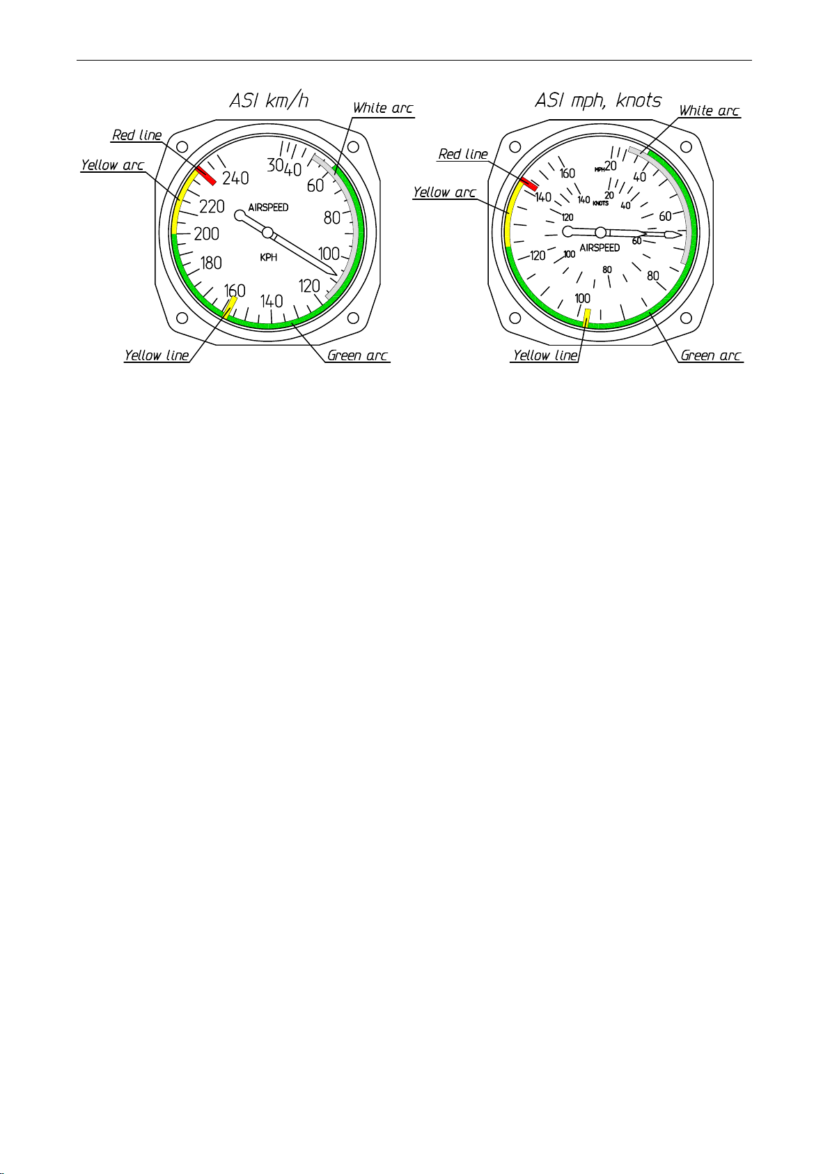
Scheme of color markings of airspeed indicator is shown on Fig. 1. Explanations are given
in the table below:
Marking
IAS range or value
Significance
White arc
50 –117 km/h
31 –73 mph
27 –63 kts
Positive flap operating range
Green arc
60 –200 km/h
38 –124 mph
33 –108 kts
Normal operating range
Yellow arc
200 –230 km/h
124 –143 mph
108 –124 kts
Maneuvers must be conducted with caution and only
in smooth air
Yellow line
158 km/h
98 mph
85 kts
Design Maneuver Speed
Red line
230 km/h
143 mph
124 kts
Maximum speed for all operations
AEROPRAKT-32 Pilot Operating Handbook A32-240-POH
8
Fig. 1 Airspeed Indicator markings
2.2 Operating weights and loading
Maximum takeoff weight: 450 kg (992 lb).
Empty weight: according to actual weighing.
Maximum fuel weight: 65 kg (143 lb) –standard tanks; or 82 kg (181 lb) –optional tanks.
Maximum baggage weight (in container): 30 kg (66 lb).
Permissible CG range: 19 to 37 % of wing MAC (mean aerodynamic chord).
The airplane may be flown by 1 or 2 pilots. Total weight of pilots, fuel and baggage may not
exceed the maximum useful load (maximum takeoff weight less actual empty weight).
2.3 Service ceiling
Service ceiling of A-32 with Rotax-912ULS (100 hp) engine is equal to at least 5000 m
(16 000 ft).
However, A-32 has neither pressurized cockpit nor oxygen equipment and therefore may
not be used for high-altitude flight.
2.4 Maneuvering load factors
Limit load factors for the airplane at gross weight of 450 kg (992 lb) are as follows:
Maximum positive limit load factor +4.0
Maximum negative limit load factor -2.0
2.5 Approved maneuvers
A-32 airplane belongs to a non-aerobatic category. All maneuvers shall be done within its
airspeed and maneuvering load factor limits (G limits). Approved maneuvers include:
- turns with bank angles up to 60°,
- level and accelerated stalls without spinning,
- diving at a speed below VNE of 230 km/h (143 mph, 124 kts) IAS.
Any aerobatics including intentional spinning is prohibited!

AEROPRAKT-32 Pilot Operating Handbook A32-240-POH
9
2.6 Fuel capacity and type
standard
optional
Capacity of tanks:
2×45 l
(2×11.9 US gal)
2×57 l
(2×15.05 US gal)
Total fuel capacity:
90 l
(23.8 US gal)
114 l
(30.1 US gal)
Total usable fuel:
88 l
(23.3 US gal)
112 l
(29.6 US gal)
Non-usable fuel:
2 l
(0.5 US gal)
2 l
(0.5 US gal)
Approved fuel types: see the table in the paragraph 2.7 Engine.
NOTE: The readings of the fuel level indicators have to be read as follows (for both
standard and optional fuel tanks):
«F» —42 l (11.1 US gal);
«3/4» — 32 l (8.4 US gal);
«1/2» — 21 l (5.5 US gal);
«1/4» — 14 l (3.7 US gal);
«E» — 4.5 l (1.2 US gal);
«LOW FUEL» lamp is ON — less than 4.5 l (1.2 US gal).
2.7 Engine
Engine data and operational limitations (as specified in the "OPERATORS MANUAL FOR
ROTAX ENGINE TYPE 912 SERIES") are given in the table below:
Engine manufacturer
BRP-Rotax GmbH&Co KG, Austria
Engine model
Rotax-912UL
Rotax-912ULS
Take-off performance
59.6 kW
73.5 kW
Max. continuous performance
58 kW
69 kW
Take-off speed
5800 rpm (max. 5 min.)
Max. continuous speed
5500 rpm
Idle speed
min. 1400 rpm
Oil pressure
max.
7 bar (102 psi)
min.
0.8 bar (12 psi) (below 3500 rpm)
normal
2.0 to 5.0 bar (27–73 psi) (above 3500 rpm)
Oil temperature
max.
140 °C (285 °F)
130 °C (266 °F)
min.
50 °C (120 °F)
normal
approx. 90 to 110 °C (190-230 °F)
Exhaust gas temperature, max.
880 °C (1616 °F)
Coolant temperature limit
measured in cylinder head
max. 120 °C (248 °F)
Engine start, operating
temperature
max.
50 °C (120 °F) (ambient temperature)
min.
-25 °C (-13 °F) (oil temperature)
Fuel pressure
max.
0.5 bar (7.26 psi)
AEROPRAKT-32 Pilot Operating Handbook A32-240-POH
10
min.
0.15 bar (2.2 psi)
Fuel
antiknock properties
min. RON 90 (min. AKI 911)
min. RON 95 (min. AKI 91)
European standard
EN 228 normal, EN 228
super, EN 228 super plus
EN 228 super,
EN 228 super plus
Aviation standard
AVGAS 100 LL
(ASTM D910)
AVGAS 100 LL
(ASTM D910)
Oil:
with RON 424 classification
NOTE: On all issues of engine operation refer to Rotax engine Operator's Manual.
Follow its instructions to ensure safe and efficient operation of the engine.
2.8 Kinds of operation limits
This aircraft is approved for flying day and night, VFR, simple meteorological conditions.
Flight into icing conditions is prohibited.
2.9 Crosswind limitation
Maximum crosswind component for A-32 airplane is 7 m/s (14 kts).
It is highly recommended to choose upwind direction for takeoff and landing with the least
crosswind. It will significantly shorten takeoff and landing distances and increase degree of
safety.
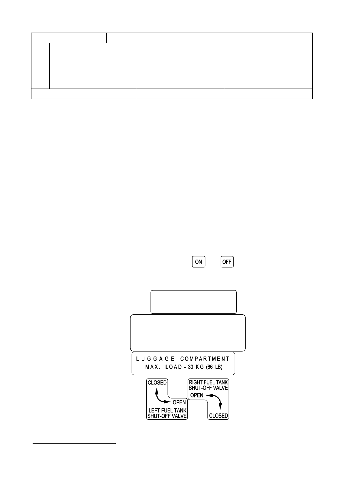
2.10 Markings and placards
The markings and placards are made using pieces of sticking film with inscriptions.
All switches for electrical systems are switched ON when moved UP, and switched OFF
when moved DOWN.
The respective switches' positions are marked with: and labels.
Apart from the individual markings of the instruments, controls and switches there are
placards and markings with the following information:
•Prohibited aerobatic maneuvers:
•Limit aircraft loading data:
•Maximum luggage weight:
•Settings of fuel shut-off valves:
1
Anti Knock Index (RON+MON)/2
ANY AEROBATIC MANOEUVRES
AND INTENTIONAL SPINNING
ARE PROHIBITED
MAXIMUM WEIGHT 450 KG (992 LB)
MINIMUM LOAD IN COCKPIT –60 KG (132 LB)
MAXIMUM LOAD IN COCKPIT
WITH FULL FUEL TANKS –100 KG (220 LB)

AEROPRAKT-32 Pilot Operating Handbook A32-240-POH
11
•Fuel grade marking on the fuel inlet caps:
Beside the above mentioned markings there is a fire-resistant aircraft identification plate
made off 1 mm aluminum sheet that is attached with rivets to fuselage structure in a clearly
visible place (left-hand side, rear vertical beam of the entrance door opening) with the
required aircraft data engraved on the plate (see the picture below).

AEROPRAKT-32 Pilot Operating Handbook A32-240-POH
12
3 Emergency procedures
3.1 General
This section contains recommendations to the pilots in case of emergency in flight. However
such situations, caused by airframe or engine malfunction are extremely rare provided that
pre-flight inspections and checks are performed regularly.
3.2 Emergency checklists
3.2.1 Engine fire during start (on the ground)
1. Throttle –IDLE.
2. Ignition –OFF.
3. Fuel valves –CLOSE.
4. Unfasten seat belts, abandon cockpit.
5. Take measures to extinguish the fire.
3.2.2 Engine failure during takeoff
3.2.2.1 during takeoff roll
1. Throttle –IDLE.
2. Ignition –OFF.
3. Brakes –APPLY as necessary.
3.2.2.2 immediately after takeoff
1. Direction –NO TURN BACK.
2. Airspeed –110 km/h (68 mph, 59 kts) –best glide.
3. Throttle –IDLE.
4. Ignition –OFF.
5. Master switch –OFF.
6. Fuel valves –CLOSE.
7. Landing –STRAIGHT AHEAD, avoid colliding with obstacles.
3.2.3 Loss of engine power in flight
3.2.3.1 during climb
1. Airspeed –110 km/h (68 mph, 59 kts) –best glide.
2. Throttle –IDLE.
3. Ignition –OFF.
4. Fuel valves –CLOSE.
5. Direction –TURN to the airfield (if altitude permits).
6. Landing –STRAIGHT AHEAD, avoid colliding with obstacles.

AEROPRAKT-32 Pilot Operating Handbook A32-240-POH
13
3.2.3.2 in level flight
1. Airspeed –110 km/h (68 mph, 59 kts) –best glide.
2. Landing area –SELECT (consider altitude and wind).
3. Engine –RESTART (if time and altitude permit), see section 3.2.4.
4. Unable to restart –follow emergency landing procedure, see section 3.2.5.
3.2.4 Restarting engine in flight
1. Throttle –IDLE.
2. Fuel valves –check OPEN.
3. Fuel level –CHECK.
4. Ignition –ON.
5. Master key –turn to START.
3.2.5 Emergency landing without engine power
1. Airspeed –110 km/h (68 mph, 59 kts) –best glide.
2. Flaps –position 1.
3. Ignition –OFF.
4. Fuel valves –CLOSE.
5. Landing area –SELECT, consider altitude and wind. (No place suitable for landing –use
recovery system.)
6. Emergency call –TRANSMIT (121.5 MHz or nearest airfield frequency).
7. Flaps –EXTEND FULLY on final.
8. Landing –in the SELECTED place, avoid colliding with obstacles.
9. Touchdown –at minimum speed.
3.2.6 Precautionary landing with engine power
(In case of decision to discontinue the flight with engine running)
1. Airspeed –SELECT SAFE for the particular situation.
2. Throttle –SET to maintain selected airspeed.
3. Fuel –CHECK level and valves.
4. Map –CHECK for nearest airfields/area suitable for landing.
5. Landing area –SELECT.
6. Radio –REPORT decision to land on the selected place if necessary.
7. Landing –follow NORMAL or SHORT-FIELD landing procedure as appropriate.

AEROPRAKT-32 Pilot Operating Handbook A32-240-POH
14
3.2.7 Fire in flight
1. Ignition –OFF.
2. Fuel valves –CLOSE.
3. Yoke/Stick –PUSH to descend.
4. Airspeed –BELOW 230 km/h (143 mph, 124 kts).
5. Landing area –SELECT (consider altitude and wind).
6. Landing –in the SELECTED place, avoid colliding with obstacles.
7. Unfasten seat belts, abandon cockpit.
8. Take measures to extinguish the fire.
3.2.8 Loss of oil pressure
1. Follow PRECAUTIONARY LANDING procedure, see section 3.2.6.
2. Engine overheating or stopped –follow EMERGENCY LANDING procedure, see section
3.2.5.
3.2.9 High oil pressure
1. Throttle –REDUCE rpm, IDLE if necessary.
2. Airspeed –110 km/h (68 mph, 59 kts) –best glide.
3. Oil pressure –CONTROL.
4. Oil pressure normal –follow PRECAUTIONARY LANDING procedure, see section 3.2.6.
5. Oil pressure high –follow EMERGENCY LANDING procedure, see section 3.2.5.
3.2.10 Emergency descent
1. Yoke/Stick –PUSH to descend.
2. Throttle –IDLE.
3. Airspeed –BELOW 230 km/h (143 mph, 124 kts).
4. Engine speed –BELOW 5800 rpm.
5. Air traffic –CONTROL to avoid collisions.
6. Altitude –CONTROL.
7. Terrain –CONTROL.
8. At safe altitude –PULL YOKE GENTLY to level off.
9. G loads –DO NOT EXCEED +4g.
3.2.11 Alternator failure
Follow PRECAUTIONARY LANDING procedure, see section 3.2.6.
3.2.12 Overvoltage
1. Additional electrical consumers (landing light, strobes, etc.) –switch ON.
2. Voltage –CHECK.
3. Voltage normal –CONTINUE normal flight.
4. Voltage high –REMOVE battery charge fuse and FOLLOW PRECAUTIONARY
LANDING procedure, see section 3.2.6.

AEROPRAKT-32 Pilot Operating Handbook A32-240-POH
15
3.2.13 Inadvertent spin
1. Rudder pedals –FULLY AGAINST ROTATION.
2. Yoke/Stick –PUSH slightly forward of neutral.
3. Rotation stopped –rudder pedals NEUTRAL.
4. Speed reached 110 km/h (68 mph, 59 kts) –PULL YOKE GENTLY to recover from
diving.
Do not exceed +4g and 230 km/h (143 mph, 124 kts)!
WARNING: Intentional spinning in A-32 is prohibited!
NOTE: In level flight and during turn stall warning is assured by the aerodynamic
characteristics of A-32 –gentle shaking of the airplane and yoke/stick due to the
starting airflow separation.
3.2.14 Inadvertent icing encounter
1. Abandon icing build-up area.
2. Icing build-up not stopped –FOLLOW PRECAUTIONARY LANDING procedure, see
section 3.2.6.
3.2.15 Loss of primary instruments
3.2.15.1 ASI failure due to full pressure line blockage
Signs of the blockage –airspeed indicator reading either:
- does not change with changing airspeed in level flight or,
- reduces during a steady descent or,
- increases during a steady climb.
1. Airspeed indicator readings –IGNORE.
2. In level flight –SET THROTTLE to 4000-4500 rpm.
3. Altitude –MAINTAIN.
4. In descent –SET THROTTLE to IDLE.
5. Sink rate –SET to 3 m/s (600 ft/min).
6. Follow PRECAUTIONARY LANDING procedure, see section 3.2.6.
3.2.15.2 Altimeter, VSI and ASI failure due to static pressure line blockage
Signs of the blockage:
- altimeter and vertical speed indicator readings do not change with changing altitude or,
- airspeed indicator reading increases during a steady descent or,
- airspeed indicator reading reduces during a steady climb.
1. IGNORE altimeter, VSI and ASI readings.
2. Airplane attitude –CONTROL by the position of the horizon line with relation to the wings
and engine cowling.
3. Airspeed and vertical speed –CONTROL using throttle.
4. Follow PRECAUTIONARY LANDING procedure, see section 3.2.6.

AEROPRAKT-32 Pilot Operating Handbook A32-240-POH
16
3.2.15.3 Powerplant instruments failure
(Tachometer, oil, water and exhaust temperature indicators, fuel quantity indicator)
1. IGNORE powerplant instruments readings.
2. Engine rpm –CONTROL by engine noise.
3. Follow PRECAUTIONARY LANDING procedure, see section 3.2.6.
3.2.16 Loss of flight controls
1. Elevator control fails –use elevator TRIM TAB control.
2. Rudder control fails –use AILERONS to control direction.
3. Aileron control fails –use RUDDER to control bank.

AEROPRAKT-32 Pilot Operating Handbook A32-240-POH
17
4 Normal Procedures
4.1 General
This section describes normal procedures recommended for safe operation of the A-32.
4.2 Preflight check
Pilots must inspect the general condition of the airplane during its preflight check. The
airplane must have no damage or maladjustments that may be critical for the flight safety.
The cockpit glass, propeller, wing and empennage must be clean of rainwater, snow, frost,
ice, and dirt as they impair visibility and aerodynamics and increase weight.
Preflight check must be performed according to the following order and requirements:
4.2.1 Entire airplane
1. Covers and clamps –REMOVED.
2. Airplane –CLEAN of rainwater, snow, frost, ice and dirt.
3. Rigging –CHECK visually.
4. External damage –NONE.
4.2.2 Power plant
1. Propeller and spinner –CLEAN, INTACT and SECURE.
2. Top cowling –REMOVE for engine inspection.
3. Oil, coolant and braking fluid –CHECK level.
4. Engine mount and vibration dampers –NO CRACKS and INTACT.
5. Cables and hoses –INTACT and SECURE.
6. Fuel, oil, coolant leaks –NONE.
7. Exhaust system, its attachments, joints and springs –NO CRACKS and INTACT.
8. Top cowling –INSTALL back.
9. Cowling and its locks –INTACT and LOCKED.
4.2.3 Landing gear
1. Wheel fairings –CLEAN, INTACT and SECURE.
2. Wheel pressure –OK.
3. Tires –NO CRACKS, WEAR OK.
4. Main wheel brakes –CLEAN, INTACT and SECURE.
5. Braking fluid –NO LEAKS.
6. Nose and main legs –NO CRACK and INTACT.
7. Nose leg shock absorber –INTACT.
4.2.4 Right wing
1. Wing and strut surface –CLEAN and INTACT.
2. Wing and strut attachment fittings and bolts –IN PLACE, INTACT and SECURE.

AEROPRAKT-32 Pilot Operating Handbook A32-240-POH
18
3. Wing fuel tank cap –IN PLACE and SECURE.
4. Fuel leaks –NONE.
5. Fuel tank vent outlet –CLEAN and INTACT.
6. Wing tip and navigation/strobe light –INTACT.
7. Flaperon clamp –REMOVED.
8. Tie-down ring –REMOVED.
9. Flaperon –CLEAN and INTACT.
10. Flaperon hinge brackets –INTACT, BOLTS SECURE, HINGES GREASED.
11.Flaperon control linkage attachment –INTACT and SECURE.
4.2.5 Right side of fuselage
1. Fuselage surface –CLEAN and INTACT.
2. Cockpit glass –CLEAN, INTACT and NO CRACKS.
3. Door hinges and lock –INTACT.
4. Recovery system condition –CHECK visually.
5. Drain valve –CLOSED, NO FUEL LEAKS.
6. Fuel residue –DRAIN and CHECK.
4.2.6 Empennage
1. Empennage surface –CLEAN and INTACT.
2. Clamps/stops –REMOVED.
3. Horizontal stabilizer attachment fittings and bolts –INTACT and SECURE.
4. Rudder, elevator and trim tab –CLEAN and INTACT.
5. Rudder, elevator and trim tab hinge brackets –INTACT, SECURE and GREASED.
6. Rudder, elevator and trim tab control linkage attachment –INTACT and SECURE.
4.2.7 Left side of fuselage
1. Fuselage surface –CLEAN and INTACT.
2. Cockpit glass –CLEAN, INTACT and NO CRACKS.
3. Door hinges and lock –INTACT.
4. Battery and power cables' attachment –SECURE, CONDITION OK.
5. Control system linkages inside the rear fuselage –CHECK visually.
6. Baggage container condition –CHECK visually.
4.2.8 Left wing
1. Flaperon control linkage attachment –INTACT and SECURE.
2. Flaperon hinge brackets –INTACT, BOLTS SECURE, HINGES GREASED.
3. Flaperon –CLEAN and INTACT.
4. Flaperon clamp –REMOVED.

AEROPRAKT-32 Pilot Operating Handbook A32-240-POH
19
5. Tie-down ring –REMOVED.
6. Fuel tank vent outlet –CLEAN and INTACT.
7. Fuel leaks –NONE.
8. Wing fuel tank cap –IN PLACE and SECURE.
9. Wing tip and navigation/strobe light –INTACT.
10. Wing and strut attachment fittings and bolts –IN PLACE, INTACT and SECURE.
11.Wing and strut surface –CLEAN and INTACT.
12.Pitot/static pressure probe –COVER REMOVED, CLEAN and INTACT.
4.2.9 Cockpit
1. Cockpit interior –CLEAN, INTACT, NO FOREIGN OBJECTS.
2. Seats –INTACT, ADJUSTED and SECURE.
3. Harness belts –INTACT, ADJUSTED and LOCKED (with pilots in the seats).
4. Doors –CLOSED and LOCKED.
5. Flight planning including weight and CG check –PERFORMED.
6. Onboard documentation/maps required for the flight –AVAILABLE.
7. Baggage container –BAGGAGE SECURED, CONTAINER CLOSED.
8. Starter key –REMOVED
9. All electrical switches –OFF.
10.Flight instruments –INTACT, CHECK READINGS.
11.Movements of controls –check FREE and FULL.
12.Yokes/Stick, rudder pedals, elevator trim tab lever –NEUTRAL.
13.Flaps –RETRACTED.
14.Parking brake –ON.
4.3 Fuel levels, fuel valve settings and respective actions
1. BOTH TANKS ARE FULL –CLOSE ONE OF THE FUEL VALVES (to prevent fuel
escaping from the tanks through the air vent).
2. FUEL LEVEL IS BETWEEN 3/4 AND 1/4 IN ONE OF THE TANKS –OPEN BOTH FUEL
VALVES. It is recommended to keep the fuel level equal in both tanks by using the fuel
valves.
WARNING: Before closing one of the fuel valves in flight make sure that the other
valve is open!
3. FUEL LEVEL IS BELOW 1/4 IN ONE OF THE TANKS –BOTH FUEL VALVES MUST
BE ALWAYS OPEN.

AEROPRAKT-32 Pilot Operating Handbook A32-240-POH
20
4.4 Engine starting
4. Starter key –INSERT, set to ON.
5. Fuel level –CHECK (see 4.3).
6. Fuel valves –CHECK (see 4.3).
7. Throttle –IDLE.
8. Doors –check CLOSED.
9. Choke lever (cold engine only) –set FULLY FORWARD.
10. Propeller –CHECK CLEAR.
11. Starter key (cold engine only) –set to START for 5 seconds with ignition OFF.
12.Ignition –ON.
13.Starter key –set to START until engine starts (10 seconds maximum).
14.Throttle –set MINIMUM STABLE REVOLUTIONS (approx. 1600-1700 RPM).
15.Choke lever –FULLY BACK (gradually, when engine runs smoothly).
16.Engine –WARM UP at 2000-2500 RPM.
17.Required electric equipment/instruments –switch ON and ADJUST.
18.Ignition –TEST at 4000 RPM holding brakes.
19.Oil pressure –check 2.0-5.0 bar (29-73 psi) at above 3500 RPM.
4.5 Taxiing
1. Throttle –IDLE.
2. Taxiway –CHECK CLEAR.
3. Coolant and oil temperature –CHECK.
4. Parking brake –OFF.
5. Throttle –SET REQUIRED TAXI SPEED.
6. Yoke/Stick –elevator NEUTRAL, ailerons AGAINST crosswind.
7. Brakes –use as required, set throttle to IDLE when stopping.
8. To stop immediately –IGNITION OFF and ENGAGE BRAKES.
4.6 Before takeoff
1. Hold position –LINE UP AND WAIT.
2. Brakes –ENGAGE.
3. Coolant temperature –CHECK minimum 140°F (60°C).
4. Oil temperature –CHECK minimum 120°F (50°C).
5. Fuel level –CHECK (see 4.3).
6. Fuel valves –CHECK (see 4.3).
7. Flaps –EXTEND position 1.
This manual suits for next models
1
Table of contents
Popular Toy manuals by other brands


Mega Bloks
Mega Bloks HELLO KITTY 109561 manual

REVELL
REVELL F-4F Phantom II Assembly manual

ATOMIC MASS GAMES
ATOMIC MASS GAMES MARVEL CRISIS PROTOCOL MINIATURES GAME SENTINEL MK... Assembly guide

Fisher-Price
Fisher-Price LittlePeople Fun Sounds Garage 72693 instructions

Trix
Trix Ee 3/3 manual

Eduard
Eduard Zoom Kittyhawk Mk.III quick start guide