AES global iGate Prime 6 4G User manual

NEED MORE ASSISTANCE?
+44 (0)288 639 0693
SCAN THIS QR CODE TO BE BROUGHT TO OUR RESOURCES PAGE.
VIDEOS | HOW-TO GUIDES | MANUALS | QUICK START GUIDES
LIGHTNING PRONE AREAS MUST USE SURGE PROTECTION
FOR POWER SUPPLY!
Optional
Exit Button Separate
lock PSU
Magnetic
Lock
Driveway
Gates
Gate
Controller
N/C
Relay1
Relay 2
COM
N/C
N/O
COM
N/C
N/O
Relay Connections
4
See overleaf for
more PCB details
Turn Over
1
Site Wiring
TIP: Most technical calls received are due to installers using CAT5 or alarm cable
to power the unit.
NEITHER are rated to carry enough power! ( 1.2amp peak )
Please use the following cable:
Up to 2 metres ( 6 feet ) –Use minimum 0.5mm2( 18 gauge )
Up to 4 metres ( 12 feet ) –Use minimum 0.75mm2 ( 16 gauge )
Up to 8 metres ( 24 feet ) –Use minimum 1.0mm2( 14 gauge )
POWER CABLE KEEP POWER SUPPLY AS CLOSE AS POSSIBLE.
Power
Consumption:
Standby = 80mA
Peak = 1.2A
INGRESS PROTECTION
We recommend sealing all entry holes for prevention of insects that can
cause issues with a risk of shorting out components.
To maintain the IP55 rating please follow the sealing instructions included.
(also available online)
Power
3
DC24v IN
(Polarity Protected)
2
iGate Enclosure
(Install at height to allow the
internal antenna to find signal.)
DC Power Cable
(1.0mm2–8m MAX)
Keep PSU as close to the unit as possible
& Do not share PSU with other devices.
iGate Prime 6 4G - Advanced GSM Switch
STILL HAVING TROUBLE?
Find all of our support options such as Web Chat,
Full Manuals, Customer Helpline and more on
our website:
WWW.AESGLOBALONLINE.COM
* ALWAYS TEST THE UNIT ON SITE BEFORE INSTALLATION TO AVOID RE-STOCKING FEE * See full T&C’s on our website
Note: PSU not supplied.
Can be purchased separately. 24v DC 1.2A peak.
SIM Preparation
Ensure you read all instructions before
continuing.
The SIM cards provided need activated
before use. Follow the instructions
provided or visit our telecoms website for
more details:
www.aesglobaltelecom.com
1
Ensure there is good
4G signal on site. 4G
units will fall back to
3G service in some
countries.
SITE SURVEY
This product requires a regular voice & SMS SIM card.
Do not use a data only SIM, as this will not work in the unit.
Set up on a bench in workshop
BEFORE going to site.
Program the unit in the comfort
of your work bench and call
technical support should you
have any questions.
Please read this entire manual before installing this
product. A full comprehensive manual is available on
our website for additional information.

SIM ORIENTATION
ALWAYS ensure the system is
switched OFF when adding or
removing your SIM card and ensure
the orientation is correct.
CONNECTION TO NETWORK
Quick Flashing =Standby | Constant ON/OFF = Searching
ALTERNATIVE WIRING EXAMPLE
MODEM LED
INDICATOR
Wiring Connections
( LINKING WITH SECONDARY RELAY IS OPTIONAL )
INTERCOM
SECONDARY
INTERCOM
SECONDARY
MAGNETIC LOCK
STRIKE
LOCK
ALTERNATIVE WIRING EXAMPLE
( LINKING WITH SECONDARY RELAY IS OPTIONAL )
LOCK POWER
SUPPLIES
ARE NOT
INCLUDED AS
PART OF THE
KIT.
SIM
PCB Status LEDs
SOLID RED = PCB POWERED ON
SOLID RED +BLUE FLASHING = SEARCHING
SOLID RED + BLUE FLASHING + GREEN FLASHING = SUCCESSFULLY CONNECTED
DETECT
Gate Position
Limit switch
(optional)
OPEN
Exit Button
(optional)
Relay 1Relay 2
Tip: All main connections are pre-wired. Below are
optional wiring additions for 3rd party controllers.
Note: The supplied enclosure is fully sealed. You will need to drill a hole in the wall of the enclosure
then secure each half of the supplied cable gland into place to ensure the waterproof seal in intact.
(ensure you do not drill the hole larger than the gland supplied)
iGate Prime 6 4G - Advanced GSM Switch
STILL HAVING TROUBLE?
Find all of our support options such as Web Chat,
Full Manuals, Customer Helpline and more on
our website:
WWW.AESGLOBALONLINE.COM
* ALWAYS TEST THE UNIT ON SITE BEFORE INSTALLATION TO AVOID RE-STOCKING FEE * See full T&C’s on our website
CHANGE APN (for VoLTE / 4G services)
Check with your network provider for the correct APN for 4G data.
Once you have confirmed the APN enter it in place of ‘APNinfo’ in an SMS to the intercom.
via SMS
(if connected to network)
9999#97APNinfo#
Passcode APN info
for SIM
network
Command
(add APN)
The system will be pre-programmed with the APN for the Vodafone network. If you wish to
use a different network then the correct APN must be set for full operation.
Search for
‘APN Flyer – PRIME’
Ensure the PCB is powered on and connected
to the network with a GREEN flashing LED.
Then send the below text as an SMS to the
intercom Sim number. A power reboot is
required after the ‘OK’ reply message is
received back.
RESERVED FOR NEW APN
PROCESS IN DEVELOPMENT

Download the programming app.
‘Cellcom Prime Programmer’
Note: Slight differences will be seen between the Android and iOS app versions, any major differences will be highlighted in the screenshots below.
Tip: New app release late 2021
Tip: This product is programmed via SMS.
This app is designed to assist with creating
the correct text strings. The app does not
directly control the intercom!
Register your
details
2
Programming an EXISTING Install
1.) Go to MORE>CLIENT LIST to reveal the
screen shown.
2.) iPhone users press the info symbol.
Android users press and hold the client, and
then press upload to begin programming.
3b
Programming a Brand-New Install
Press SETTINGS to reveal the
screen shown. This screen will
store details for the client.
3
Note: You need to send the SMS message created by the app to the intercom SIM number and receive the ‘OK’ reply for correct programming. .
Enter up to 8 numbers per
SMS for CallerID & press
save to create the text string.
(max 250 separate numbers)
3
Download the App and Accept
all permissions when the app is
opened
1
9999#72telephonenumber#
Direct SMS
Add Caller ID Numbers
Basic Programming Setup
iGate Prime 6 4G - Advanced GSM Switch
STILL HAVING TROUBLE?
Find all of our support options such as Web Chat,
Full Manuals, Customer Helpline and more on
our website:
WWW.AESGLOBALONLINE.COM
* ALWAYS TEST THE UNIT ON SITE BEFORE INSTALLATION TO AVOID RE-STOCKING FEE * See full T&C’s on our website
RESERVED FOR NEW APP IN DEVELOPMENT.
RELEASE DUE LATE 2021

4
INFORMATION (SMS Reply Examples)
VOLUME CONTROL
NOT USEABLE IN THE
iGATE RANGE
DIALING TIMES
NOT USEABLE IN THE
iGATE RANGE
SERVICE CALLS
Prevent SIM being turned
off due to inactivity.
INFORMATION
Check firmware version,
signal levels and stored data
PASS CODES
Programmer and user pass
codes
RELAY TIMES
Change relay pulse times
NOTIFICATIONS
Turn on SMS notifications
when gates triggered.
KEYPAD PROGRAMMING
NOT USEABLE IN THE
iGATE RANGE
AUTO RELAY TIMES
Time clock automatic
opening and closing times
CLIENT INFORMATION
Adjust, add or delete clients
on your client list
DO NOT DISTURB
NOT USEABLE IN THE
iGATE RANGE
CLOCK SYNC
Turn on Auto-clock sync
after power failures PROX PROGRAMMING
NOT USEABLE IN THE
iGATE RANGE
Advanced Programming Setup
Note: You need to send the SMS message created by the app to the intercom SIM number
and receive the ‘OK’ reply for correct programming. .
STORED NUMBERS
I=Dial IN Caller ID number.
N = Another message to follow
E = End of messages
RELAY STATUS
OPEN –Shows status of the input
terminals called DETECT - Can be used
with a limit switch. Relay status shown to
check if any relay is latched.
Last 6 digits of caller ID user phone number
ACTIVITY LOG
Use this to see who used the intercom and when. Which
pin codes were used, who used caller ID, who answered
the call.
TIP: Time and date is in international military format.
Firmware:Cellcom Prime
V2.0.1
Network mode:4G
Date:22/06/21
Time:12:14
Signal level:18
APN:wap.vodafone.co.uk
SIGNAL STRENTH
Will reply with signal range 1-31.
Min signal level should be 10 on
4G systems
Tip: New app release due late 2021
iGate Prime 6 4G - Advanced GSM Switch
STILL HAVING TROUBLE?
Find all of our support options such as Web Chat,
Full Manuals, Customer Helpline and more on
our website:
WWW.AESGLOBALONLINE.COM
* ALWAYS TEST THE UNIT ON SITE BEFORE INSTALLATION TO AVOID RE-STOCKING FEE * See full T&C’s on our website
I1:987654321,
I2:321654987,
I3:658974125,
I4:96857412,
I5:78451254,
I6:96352876, E
1345-05/06/21-CID-543210
0840-04/06/21-CID-995555
1015-02/06/21-CID-995555
0840-02/06/21-CID-543210
0930-01/06/21-CID-543210
SIM MAINTENANCE
If using a pre-pay casual SIM card it will need topped up occasionally. It is recommended to
advise the home owner / end user to register the SIM card on the provider’s web site if
available. Most major networks allow registration of card payment details for an auto top up
feature, which means they will automatically top up your intercom when the balance runs
low or in some cases, they offer a low balance reminder to be sent if they do not wish the
auto top up feature.
ENVIRONMENTAL INFORMATION
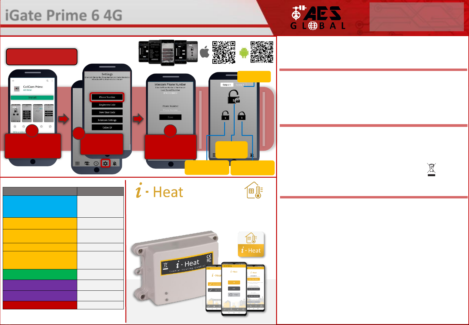
Using End User App to Manage Gates
WARRANTY
5
Please note, by installing this product, you are accepting the following warranty terms:
1. The manufacturer’s warranty is a “return to base” 2 year warranty from date of manufacture. This means that any suspected defective
components or items are returned to the manufacturer’s agent for investigation and diagnosis and returned at the cost of the customer.
2. The warranty does not cover, nor is the manufacturer or agent responsible for any of the following whatsoever: Storm damage,
lightning or surge damage, flooding, accidental damage, vandalism or deliberate damage, un-explained corrosion or unusually harsh
environments, failure of telephone networks, future un-interoperability between the product and network providers which cause mal-
function due to changes implemented by the phone providers after manufacture of the product, or that which is outside of control of
the manufacturer (e.g. 2G, 3G switch off, removal or inability to obtain VOLTE service), and damage due to inaccurate installation.
3. The manufacturer in no way accepts liability for any of the following incurred due to a product defect: Cost of attending site,
inconveniences, labor rates, time lost, loss to or damage to property, security breaches, late payment clauses or breaches of any
contracts between the installer and the client.
4. This is a professional install product only. The product is a component of an overall system. Therefore, it is the responsibility of the
installer to certify the safety and compliance of the overall finished system. As soon as this product is fixed to another item, or
connected to another third-party device, then the product has been modified, and compliance with local regulations in the country of
install is strictly the responsibilityof the installer.
5. Re-stocking fees may apply to items returned that are found to be non-defective. Complete units will also attract a re-stocking fee if
returned for credit, regardless if a defect is discovered or not. Re-stocking fees may vary depending on the condition of the item being
returned, and whether it can be determined as in brand new condition. The warranty terms do not entitle customers to an automatic full
refund. For more details on returns procedures and re-stocking fees, contact the agent.
6. Items with physical signs of surge damage are not covered by warranty. Items with visible signs of surge damage will only be covered
by warranty if photographic evidence is provided from site, showing surge protection has been installed.
Full warranty terms and conditions available upon request to AES Technical Department.
SWITCH MAINTENANCE
Bug ingress is a common issue in unit failures. Ensure that all components are sealed
accordingly and check occasionally. (Do not open the panel in the rain / snow unless correctly
equipped to keep the internals dry. Ensure the unit is securely closed after maintenance)
The equipment that you bought has required the extraction and use of natural resources for its
production. It may contain hazardous substances for the environment. In order to avoid the
dissemination of those substances in our environment and to diminish the pressure on the natural
resources, we encourage you to use the appropriate take-back systems. Those systems will reuse or
recycle most of the materials of your end-of-life equipment.
The crossed-bin symbol marked in your device invites you to use those systems.
If you need more information on the collection, reuse and recycling systems, please contact your local or
regional waste administration. You can also contact AES Global Ltd for more information on the
environmental performances of our products.
Basic SMS Strings to Manage Gates
Download the App and
Accept all permissions
when the app is opened
1
Select
Settings > Phone
Number
2
Enter the intercom
SIM number and
press SAVE
3
Switch between
output 1 and 2
Unlatch
Allow held open gates
to close via SMS.
Latch
Hold open gates via
SMS.
Trigger
Speed dial
gates to open
Download the user app.
‘Cellcom Prime’
Function
CMD String (SMS)
Manually trigger,latch or unlatch relay by SMS.
X = Relay Function.
(1 = Trigger relay 1, 2 = Latch relay 1, 3 = Unlatch relay 1)
(4 = Trigger relay 2, 5 = Latch relay 2, 6 = Unlatch relay 2)
1234
#X#
Check Intercom Status
(min signal level required for full operation is 10)
*20
#
Check Stored Numbers
O = Dial out number. I = Dial in number.
N = Another message. E = End of messages.
*21
#
Check Relay Status
*22
#
Events Log (check last 20 events, most recent first)
CID = caller ID used;
*23
#
Add Caller ID Number (max 250)
(14 digits maximum)
9999#
72number#
Change Relay Time
Time
= 1-9999 seconds
9999#
50time#
Enable Latching via DTMF (Disabled by Default)
X = 0 or 1 (0 = Disable, 1 = Enable)
9999#
95X#
Factory Reset (Default Everything)
9999
#999#
iGate Prime 6 4G - Advanced GSM Switch
STILL HAVING TROUBLE?
Find all of our support options such as Web Chat,
Full Manuals, Customer Helpline and more on
our website:
WWW.AESGLOBALONLINE.COM
* ALWAYS TEST THE UNIT ON SITE BEFORE INSTALLATION TO AVOID RE-STOCKING FEE * See full T&C’s on our website
Did you know AES Global also has a GSM central heating control
unit available the i-heat. Control your central heating and hot
water with a touch of a button using the our simple to use app!
For more information about i-Heat visit www.iheatglobal.com

TROUBLESHOOTING
Symptoms caused
Problem/error
Solution
No LEDs on.
The unit will not power up.
Check power supply voltage at intercom is 23.4v DC or more. Cable
length from PSU to intercom should be less than 8 meters and in
1.0mm2 cable for this distance. See cable guide on page 1 of this
manual. Check the fuse.
No green CPU light
The unit powers up but is not
showing network reception
or will not respond to SMS.
This means the unit is not able to detect the network for some
reason.
-Power off the unit, remove the SIM and check it in a mobile phone
to verify it can make a call and has calling credit if it is a Pay As You
Go SIM.
-
Disable any PIN code request if active on the SIM card.
-
Check the SIM is a standard voice capable SIM. If you are unsure,
contact your SIM card provider to verify.
-
Check the reception is medium or good. Poor reception is not
sufficient.
-Power off, remove the SIM, use fine sand paper to lightly sand the
SIM pads and contacts on the GSM unit, lightly bend the contacts
upwards so that they make better contact with the SIM and try
again.
-
Change to an external antenna.
External Antenna Details
-
Ensure the cable does not have too many sharp bends.
-
Check the height of the antenna and make sure it is not inside a
metal enclosure.
-Check correct power cable size for cable length from PSU. Refer to
manual for guidelines
The caller ID function
does not work.
Incorrect programming or
poor signal
If your number is a private or number withheld, then it will not
work.
-
Ensure the number is programmed as you would normally dial it
from another phone.
- Ensure you have adequate GSM signal at the intercom by sending
*20# as a text.
Manufacturer: Advanced Electronic Solutions Global Ltd
Address: Unit 4C, Kilcronagh Business Park, Cookstown, Co Tyrone, BT809HJ, UK
Complies with the following essential requirements for 2014/53/EU:
ETSI draft EN 301 489-1 V2.1.1 (2017-02) (Electromagnetic compatibility)
ETSI draft EN 301 489-52 (2016-11) (Electromagnetic compatibility,specific to cellular)
(2G bands 900/1800, 3G band1,8 LTE bands 1, 3, 7, 8, 20).
Test report number LCS181101028AEA
ETSI EN 301 511 V12.5.1 (2017-03) (3.2 of directive 2014/53/EU)
ETSI TS 151 010-1 V12.8.0 (2016-05) (Digital cellular telecoms compliance)
Test report number LCS181101028AEB
ETSI EN 301 908-1 V11.1.1(2016-07) (IMTCellular networks, 3.2 of directive 2014/53/EU)
ETSI EN 301 908-2 V11.1.2(2016-07) (CDMA spread / UTRA FDD)
Test report number LCS181101028AEC
ETSI EN 301 908-13 V11.1.2 (2017-07) (E-UTRA and UE standards)
Test report number LCS181101028AED
EN 62311 :2008 (Electromagneticsafety and human exposure)
Test report number: LCS181101028AEE
EN 60950-1, (A1, A11, A12, A2)
EN 62311
IEC 60950 (IT equipment safety)
Test report number: LCS181101029AS
The notified body is: Micom Labs (CAB number 2280).
This declaration is issued under the sole responsibility of the manufacturer.
Signed by:
Paul Creighton, Managing Director. Date: 4th Dec 2018
2280
FCC Id: 2ALPX-PRIME6-XXXX-ZZ-4GA-YYY
(XXX = style & color, YYY is brand label, ZZ is mounting
style)
Grantee: Advanced Electronic Solutions Global LLC
This device complies with Part 15 of FCC rules.
Operation is subject to the following two conditions: (1)
this device may not cause harmful interference, and (2)
this device must accept any interference received,
including interference that may cause undesired
operation.
Output power listed is ERP below 1GHz for Part 22 and
EIRP above 1GHz for Part 24. RF
exposure compliance is addressed for 1.1310 and 2.1091
MPE limits. The antenna(s) used
for this transmitter must be installed to provide a
separation distance of at least 20 cm from
all persons.
End Users must be provided with transmitter operation
conditions for satisfying RF exposure compliance.
Reset / Default Unit 1) Power off the unit. (approx 60 secs)
2) Make a link across the terminals
marked OPEN.
3) Switch on power
4) After several seconds the relay will
click.
5) The unit will then clear memory and
be defaulted
6) Remove the link and wait around 20
seconds.
Note: Performing this process will
remove all current programming
including saved users & access codes.
This product is not a complete product until fully installed. It is therefore
considered a component part of an overall system. The installer is responsible to
check that the end installation complies with local regulatory requirements. This
equipment forms part of a “fixed installation”.
6
24v DC IN OPEN
Terminals
STILL HAVING TROUBLE?
Find all of our support options such as Web Chat, Full Manuals, Customer
Helpline and more on our website:
WWW.AESGLOBALONLINE.COM
+44 (0)288 639 0693
iGate Prime 6 4G - Advanced GSM Switch
STILL HAVING TROUBLE?
Find all of our support options such as Web Chat,
Full Manuals, Customer Helpline and more on
our website:
WWW.AESGLOBALONLINE.COM
* ALWAYS TEST THE UNIT ON SITE BEFORE INSTALLATION TO AVOID RE-STOCKING FEE * See full T&C’s on our website
Table of contents
Popular Switch manuals by other brands

TRENDnet
TRENDnet TK-207K - KVM Switch - USB user guide

Leonton
Leonton CET2-0800 Series user manual

Agilent Technologies
Agilent Technologies 75000 Series C Service manual

Advance Tube Technology
Advance Tube Technology LS42 user manual

Mercusys
Mercusys MS108 installation guide

Murphy
Murphy LLS Installation and operation instructions

FS
FS IES5100-24FS quick start guide

TG-NET Botone Technology Co.
TG-NET Botone Technology Co. S2100-26G-2F Product guide

Extreme Networks
Extreme Networks VSP 4450GSX-PWR+ Quick install guide

Planet Networking & Communication
Planet Networking & Communication WGSW-48040HP user manual

ADTRAN
ADTRAN NetVanta 1560-24 quick start

HP
HP 316095-B21 - StorageWorks Edge Switch 2/24 release note


