AFWFilters 5600 Series User manual

DO NOT RETURN TO RESELLER!
Contact Us FIRST: help.afwfilters.com
For any questions, concerns, missing items, or problems contact us so
we can help. Resellers do not offer support or replacement parts.
STOPSTOP
Installation Instructions for Water Softeners
Includes Fleck 5600 and 2510 series valves
Thank You
Thank you for purchasing a new AFWFilters® Water Softener. We appreciate the opportunity
you have given us to provide you with better water. We are committed to providing the best
customer experience possible and have provided these installation instructions to make things
as simple as possible. If you have read through the instructions and FAQ section entirely and
still have questions, feel free to contact us for further help.
How To Use These Instructions
Since every installation is different we are unable
to address every possible situation that may arise.
That being said, these instructions are designed
as a general guideline for installation of your new
system. Installation will require a basic knowledge
of plumbing and plumbing connections. Pictures are
included to help identify common parts, compo-
nents, and connections, so what you have may vary
slightly from what is pictured. Please apply these
instructions with discretion and common sense.
For Questions or Troubleshooting
Most questions that arise are answered in this manual or the FAQ section at the end. If you
have read through this manual and the FAQ section and still have a question that has not
been answered, feel free to use the AFWFilters website to contact us.
Page 1
This offers vital information
that can have major impact on
your system/install/experience
Tips, tricks, and recommenda-
tions will be shown here
Answers to common questions -
A complete FAQ is at the end of this
manual

Page 2
Before You Begin
Basic plumbing skills are required for installation. If you are unsure of your abilities to install
the system using these instructions please hire a qualified plumber.
Read through your parts list and verify all components are accounted for and in good condi-
tion BEFORE scheduling a plumber.
Please read through the entire instruction manual carefully. If hiring a plumber ensure they
have a copy before they start.
Most common questions are answered in the instructions or FAQ section. If you have read
both of those and still have questions you may contact us for further help.
Plumbing related questions need to be directed to a locally qualified plumber. We are not
aware of local code requirements and are therefore not qualified to answer your plumbing
questions.
System Requirements
Your chosen installation location and water supply must meet ALL of the following require-
ments:
• 20-90 PSI (1.38-6.20BAR)
• 34-110°F (1.1-43.3°C)
• System must be protected from freezing
• Firm level surface capable of supporting the
entire system
• 3-prong, 120V outlet within 5 ft. (1.5 m) of the
control head with constant power. GFCI outlet
is recommended. Use of an extension cord is NOT
recommended.
• A 1.5 inch standpipe, sump pit, or outside drain.
Section 1: Verify System Inventory
Use the following Inventory to help verify the parts that are included with your system and
verify that they are all accounted for. Inspect all parts for damage and report any damage
immediately.
We recommend thoroughly reading these instructions BEFORE you schedule a plumber
or begin installation. This can reveal missing parts or other items that can save significant
headache if caught before you begin.
MUST be installed AFTER the
pressure tank
The drain line is pressurized and
can be ran vertically if necessary
This system requires a drain line connection from the control head to a drain (see
plumbing guidelines section). DO NOT operate the system without this connection.
Claims for damage or missing parts must be made within 30 days of delivery to be
eligible for replacement

Page 3
All Systems
Polyglass Tank - A tall slender tank 44–65 inches in height with an opening on the
top. Larger tanks may have a gray threaded adapter to reduce tank opening to match
control head.
Riser/Distributor Tube - A tall pipe that runs from the
bottom of the tank to the control valve. One end has a
basket (basket design varies) and it usually ships inside
the tank.
Control Head - Screws on top of the tank
and controls the water flow and backwashing cycles. Digital SXT has
LCD panel. The mechanical has control knobs.
Brine Tank - A large plastic
tank similar to a trash can.
Inside the tank is the brine
well—a small cylinder about 4
inches (10.1 cm) in diameter—
which contains the safety float.
There will also be an overflow
fitting and tubing. Some sys-
tems may have a salt grid—a
plastic grid on the bottom of
the tank—but most do not as
they are not needed when using
salt pellets as recommended
Systems may ship loaded, partially loaded, or unloaded. Loaded systems will have all
the resin in the tank. Partially loaded systems will have some resin in the tank and some
in one or more separate bags. Unloaded systems will have all the resin in separate bags
and the tank will be very light (less than 30 pounds).
Note for loaded or partially loaded systems: Tanks that are shipped load-
ed may arrive on their side or even upside down. The tanks are closed and the
media will return to the bottom once placed in the correct position. Any mixing
of tank contents will correct itself after being placed in service.
On loaded or partially loaded tanks - DO NOT pull the
riser tube out of the tank.
Some SXT systems may have labels referring to the older SE
model number. This is an internal designation only and does NOT
mean you received the SE. The SE controller has been discontinued
for long enough it would be impossible to send one out anymore.
This tank is to hold the
salt (NOT included). DO NOT
load resin in this tank.
After installation ensure
the salt tank has at least one
bag of salt at all times. It can
be filled clear up to the top
of the brine well if desired.
After initial regeneration,
there will always be water in
the brine tank.

Page 4
Bypass Valve - Depending on your order your system will have either a
single piece stainless steel bypass or a two part plastic bypass with yoke
connection. This is what connects to your control head and provides standard
fitting connections to hook up to your plumbing.
Meter Assembly - The flow meter connects the
control head and the bypass valve and it mea-
sures the water flow to initiate regeneration on demand. Includes
O-rings (already attached) to seal the connection and screws and
clips to secure the connection. Typically connected to the control
head when received.
Brine Connection Parts - Tubing and fittings
used to connect the control head to the
brine tank. Tubing is usually inside the brine
tank (inside the brine well), and the fittings are either in a small bag
(either with the tubing, with the instructions, or with the control head)
or already attached to the head/float. Depending
on your system you may have one or both of the
shown fittings.
Drain Fitting - The drain connection on your system is 1/2” FNTP thread,
on the 5600 it will be part of your control head while the 2510 heads
will have a quick connect fitting. If your system included a barbed fit-
ting (not all do) then it would be used with 1/2” ID tubing.
UNLOADED/PARTIALLY LOADED Systems ONLY
Gravel - Small rocks or pebbles to pro-
mote water distribution. Most standard
softeners will NOT have gravel, but Iron
Pro softeners or very large softeners
will. Amount and type of gravel will
vary depending on system type and size.
Resin/Media - The material placed in the polyglass tank
that does the actual treatment of the
water. The system should ship with the
required amount so you should use all
resin included, however, excess media
can occasionally be sent. For this
reason it is important that you pay
attention to the resin level as you fill
it, typically a fully loaded system will
be about 1/2 full. Overfilling the tank may lead to improper
system operation.
Most systems will ship loaded. Some larger systems may ship partially loaded (with
some media in the tank and some separate) or completely unloaded for easier placement.
If you system shipped loaded and did not come with extra media you can skip this section.
Unloaded Systems Only
Gravel will be loaded FIRST
Partially loaded systems
requiring gravel will already
have it in the tank
Do not overfill the tank,
typical systems will only be
around half full of resin.
Packaging for additional
resin may vary and different
packages may contain the
same resin

Page 5
Funnel (OPTIONAL) - The funnel is a complementary item that MAY be
included with some unloaded systems to help fill the polyglass tank with the
resin. If your system does not include one, a blender pitcher with the blade
assembly removed will screw onto the tank and work well.
Before You Start Plumbing
Section 2: Preinstallation Preparation
Step 2a: Verify riser tube position
Loaded/PartiaLLy Loaded SyStemS
Your system will ship with a cap de-
signed to keep the resin in the tank
during shipping. Once your system
is near the installation location,
remove the cap at the top of the tank
by unscrewing it counterclockwise.
The riser tube sits in the center of
the tank and should be no more than 1/3 inch (8 mm)
above the top lip of the tank.
Loaded SyStemS
Skip to the final step in this section
PartiaLLy Loaded SyStemS
Continue to the next step
UnLoaded SyStemS
Ensure the riser tube is positioned in the middle of the tank. There is a slight depression that
the lower basket will slip into when properly positioned. Once correctly positioned the riser
tube should be no more than 1/3 inch (8 mm) above the top lip of the tank. Continue to the
next step.
Step 2b: Fill tank partially with water -Optional-
This optional step will help buffer the resin as it is poured in and will also help minimize air
bubbles upon initial startup. Simply pour water into the tank until it is 1/4 - 1/3 filled with
water.
Step 2c: Load gravel and resin
UnLoaded/PartiaLLy Loaded SyStemS onLy
Cover the riser tube before beginning. A piece of tape
or small bag will work, you just need to prevent resin
from falling down the riser when you are loading it.
If you have it, gravel will go in first, then the rest of
the resin.
Money-saving tip: If hiring a plumber to do the installation you can save some money
by preparing the tank ahead of time. This cuts down on the time the plumber has to spend
and doing so is simple enough that most people can accomplish it in less than an hour.
Do not attempt to remove your
riser tube. Doing so will require
emptying & reloading the system.
If your riser tube is not exactly
centered that is not an issue. If it
extends more than 1/3 inch above
the top of the tank refer to the FAQ
section for ways to correct this.
Do not cut the riser tube, as this
can cause improper operation.
The resin goes in the polyglass
tank, NOT the brine tank.
Standard softeners typically do
not need gravel. Very large or fine
mesh (Iron Pro™) systems will. If
you have it, use it, and verify you
have received all boxes.

Page 6
When filling the tank, do so slowly and ensure the
riser tube stays correctly positioned and centered in
the tank. If you have more than one bag of resin the
order does not matter and all of it should be used.
Once all the resin is loaded the tank will not be com-
pletely full, this is normal.
Step 2d: Finish filling tank with water -Optional-
Once the resin is loaded and your tank is positioned you may finish filling the tank with wa-
ter. This can help reduce air bubbles and ease initial startup.
Section 3: Attach the Control Head
Step 3a: Lubricate the O-rings
The tank O-ring (Img Left) seals the control valve to the tank, and the pilot O-ring (Img Right)
seals around the riser tube. Verify they are present and free
from nicks or kinks. Use a silicone lubricant or vegetable oil
to both O-rings. It is also recommended to verify that the
riser tube fits snugly into the pilot hole and that the O-ring
seals around it.
Step 3b: If Present - Inspect and install the top distributor
basket
Depending on system configuration your system may include a top distributor basket (Img
Left). If your system includes one it is recommended that
you use it. If you do not have one then it is not needed. If
you do have one the larger end will fit inside the bottom
of your control valve, with the smaller end sliding over the
riser tube pointing down into the tank (Img Right). Please
note that locking tabs hold it in place so a fair amount of
force is needed to install or remove it.
Step 3c: Screw on control head
Ensure the riser tube slips inside the pilot opening in the bottom of the head. Screw the head
down onto the resin tank until solid contact is made
between the tank and O-ring, then tighten about
another 1/4–1/3 of a turn and STOP. Once properly
tightened down check to ensure the tank and control
head meet evenly all the way around.
If you have KDF media (heavy
gold or brown media) it will be
added to the top of the tank.
DO NOT use Teflon tape or other
sealants on the threads between
the tank and valve. Hand tighten
only.

Page 7
Section 4: Prepare and Connect the Brine Tank
Step 4a: Assemble the brine tank
The brine tank will come with the
brine well loose, either inside the brine
tank or in the box with the brine tank
(Img Left). You will use the overflow
fitting to attach it in the side of the
brine tank, placing the overflow fitting
through the lower hole on the brine tank and securing it
through the brine well with the nut (Img Right). If you are having a hard
time fitting your hand between the float and the brine well to secure the
overflow nut you can remove the float by removing the nut that holds the
float in place. Make sure to put it back when you are finished.
Step 4b: Connect brine line to control head
Locate the brine fitting on the control head (Img
Left). Using a piece of flexible 3/8 inch tubing,
place the fittings on the tubing as shown (Img
Right) and connect it to the control head. NOTE:
The 5600 series uses a brass fitting, while the 2510
series uses a plastic fitting.
Step 4c: Connect brine line to brine tank
Run the brine line through the hole in the side of the brine tank into the brine well with the
float assembly. Connect the brine line to the float assembly using the instructions for the
connection style you have.
QUick connect Fitting
If you have the quick connect
style float fitting (Img Left),
push the tubing into the fitting
until in stops, then push a little
harder to get it to lock in place.
To remove the tubing, hold the
collet ring that sits around the
tubing while pulling the tubing out.
comPreSSion Fitting
If you have the compression style fitting, remove the nut from the float and
place on the brine line as shown (Img
Right). Push the tubing fully into
the float, and tighten the nut, finger
tight only.
Step 4e Add Salt to the brine tank
Add salt to the brine tank. We recommend high
quality salt pellets designed for water softeners for
The brine well has a cap for the
top. Some may come with one for
the bottom as well, but it is not
needed.
If your brine line is not pushed
in the quick connect fitting all the
way it will not seal correctly, and
this is the most common cause of
the brine tank overfilling.
Water does not need added to
the brine tank as the manual cycle
ran at the end of the instructions
will put the correct amount in for
you. After initial regeneration there
will always be water in the brine
tank, and it may be above the salt
level without concern.

Page 8
the best results. You will need to add at least one bag of salt and can fill it up to the top of
the brine well. Ensure there is salt in the brine tank at all times. The resin is precharged and
able to treat the water out of the box. A later step will have the control head put the correct
amount of water in the brine tank for you.
Section 5: Digital Control Head Setup
Step 5a: Plug Control head in
Plug the control head into a qualifying outlet as stat-
ed in the requirements section. Once plugged in, verify
the system is receiving power and ensure the outlet is
not on a switch that might get turned off. The display
should light up and start flashing a time
Step 5b: Understanding you SXT Display
Parameter Display - During programming, indicates which setting you are on
Data Display - During programming shows setting. During normal operation alternates be-
tween current time and gallons remaining until regeneration.
Flow Indicator - Flashes to indicate water is flowing through the system.
Ensure you continue past programming for proper plumbing of the control head,
including the drain line.
If you have the mechanical valve please refer to our website for instructions.
We recommend verifying the
control valve operation BEFORE
plumbing to avoid issues.
The control head can be plugged
in and operated without water, this
will not damage the control head.
The display will normally flash between the current time and the number of gallons
remaining until regeneration. If the time is flashing that indicates power was lost and the
time needs to be set. Service icon indicates the system is IN SERVICE, not that the system
needs service.

Page 9
x1000 Indicator - Indicates current data display value is x1000.
Programming Icon - Displayed when in programming mode.
Service Icon - Indicates the system is in service (working). When flashing a regeneration will
run at the programmed time.
Error - When displayed an error code will be shown
in the parameter display. See end of programming sec-
tion for error code explanations
Extra Cycle Button - Used to initiate manual regener-
ation or advance through programming.
Up Arrow - Used to change time or increase value of current setting.
Down Arrow - Used to change time or decrease value of current setting.
Step 5c: Quick Start Guide (USER Programming)
Most systems will use default settings and there is very little that needs changed. The USER
programming has the most commonly changed settings, and you can go through the set-
tings below to get up and running quickly. To get the most efficient results, make sure to go
through the MASTER programming below and set your capacity and brine fill settings.
USER Programming Settings
Press both the UP and DOWN buttons at the same time and hold for 5-10 seconds until
the Parameter Display shows DO. Press the Extra Cycle button to advance to each setting
shown below, and adjust with the UP/DOWN buttons if necessary.
Continue pressing the Extra Cycle button until you get back to the time of day to
save your settings, or press nothing for 5 minutes to discard any changes.
Setting Parameter Value Description
Day Override DO 3-14
Sets regeneration frequency. Only used if water
usage does not initiate it first. If you have iron, set
no higher than 7, otherwise set no higher than 14. If
you have a lot of iron or very dirty water, set lower.
The service icon does NOT mean
your system needs serviced.
If this icon is NOT shown, there
is NO error present.
USER programming settings will be dependent on YOUR situation. Use the guide below
to program the correct settings. For maximum efficiency, make sure to check the MASTER
programming in the next section.
There is not an average or generalized setting that can be used for hardness. You will
need to test your water to find out YOUR hardness. Hardness maps are generalizations for
the area and your actual hardness may be much higher or lower than indicated.

Page 10
Regen Time RT 2:00
Typically set to midnight or 2am to ensure water
is not being used. If you have multiple systems,
ensure they are set at different times. Typical re-
generation process takes roughly 1.5-2 hours
Hardness H 1-199
Hardness in grains per gallon (GPG). Divide hard-
ness in ppm or mg/L by 17.1 to get GPG. If you have
iron or manganese, add 4 for each ppm.
Reserve
Capacity RC Varies Take the average number of people in the home
and multiply by 75. Use the result here.
Step 5d: Setting the Time
The display will show the time as currently programmed in the system. It can be adjusted by
simply pressing the UP or DOWN button repeatedly, holding down a button will cause time
to change quickly. You can press the Extra Cycle button to confirm the setting, or just leave it
alone for a few seconds and it will save.
Step 5e: MASTER Programming
The MASTER programming section contains ALL of the
available settings, including the settings shown in
USER programming. These settings (with the excep-
tion of the Capacity and Brine Fill settings) typically
use the default values and should not need adjusted.
MASTER Programming Settings
To enter master programming, use the UP or DOWN button to set the time of day to 12:01
PM and press the Extra Cycle button to confirm the time setting. Then press BOTH the UP
and DOWN buttons at the same time and hold for 5-10 seconds until the Parameter Display
shows DF. Adjust each setting with the UP/DOWN buttons if necessary, then press the Extra
Cycle button to advance to the next setting.
The time MUST be set to 12:01PM (PM indicator shown). If you do not get the DF
parameter, it is possible the time changed or was not set correctly. Press the extra cycle
button to get back to the time of day and try again.
The settings shown are the only ones that MAY need adjusted. If a setting is not listed in
this chart, DO NOT CHANGE IT without consulting with an expert.
Continue pressing the Extra Cycle button until you get back to the time of day to save
your settings, or press nothing for 5 minutes to discard any changes
The time will need to be
changed from the current time for
MASTER programming below
You WILL need to adjust your
capacity setting.
DO NOT change any settings unless indicated here or directed to do so by an AFWFilters
support technician. Other videos and instructions are not designed for AFWFilters systems
and may lead to improper operation. If you change a setting in the MASTER programming
that is not shown below use the system reset section to reset the system to defaults and
adjust ONLY the settings shown below and in the USER programming section.

Page 11
Setting Parameter Value Description
Valve Type VT dF1b Configures the system as a standard downflow
system with regeneration (salt) feed.
Control Type CT Fd Initiates the regeneration cycle based on water use.
Capacity C Varies Refer to Brine Fill/Capacity Settings chart below.
Reserve
Selection RS Rc Uses reserve capacity based on gallons.
Brine Fill BF Varies Refer to Brine Fill/Capacity Settings chart below
The FAQ section contains a complete listing of each setting in the MASTER program-
ming, along with more detailed information about each setting and common issues
that may arise from incorrect settings.
Brine Fill/Capacity Settings
Max efficiency settings will use less salt but regenerate more often.
Max capacity settings will regenerate less often but use more salt.
Listed Capacity (cf of Resin) Max Efficiency Settings Max Capacity Settings
Parameter C BF C BF
32k (1.0 cu ft) 21 4 32 11
40k (1.25 cu ft) 26 5 40 14
48k (1.5 cu ft) 32 6 48 16
64k (2.0 cu ft) 42 8 64 22
80k (2.5 cu ft) 52 10* 80 27*
96k (3.0 cu ft) 63 12* 96 33*
*These settings are based on a 0.5 GPM brine line flow control (BLFC) most used on
systems. Larger systems may use a 1 GPM BLFC, if so halve the shown BF setting, or
refer to the FAQ section.
Step 5f: Resetting your system
If you change a setting not listed in the programming section you can use a reset to return
everything to its default value. If your controller is showing odd behavior such as erratic
display, no display, or showing an error code, a reset can often correct the problem. Start
with the soft reset, and if that does not solve the problem move on to the master reset. If the
problem persists contact one of our technicians.

Page 12
SXT Resets
Reset Directions Effect
Soft Reset Hold Extra Cycle and Down
buttons for 25 seconds
This will reset all settings to default
values, but leaves the volume remaining
intact.
Hard Reset Hold Extra Cycle button while
plugging the unit in
This will reset everything in the system.
This should only be used if a soft reset
does not work.
Plumbing the system in
Section 7: Plumbing Guidelines
Step 7a: Connecting the bypass
The exact fittings on your system
may vary depending on the exact
configuration of your system, but in
general you will have a bypass valve
and yoke, or a single piece bypass
valve with built-in fittings (Img Left).
You will supply the required fittings
to connect from the system to your plumbing, this
will typically consist of threaded adapters that will
connect directly to the bypass/yoke, fittings to tie into
your main line, and the copper/PVC/PEX line to connect between them. Use Teflon tape, pipe
dope, or joint compound as necessary to ensure a proper seal. If soldering, first solder a short
(min 3-inch [7.6-cm]) piece of copper pipe onto the adapters, away from the valve, before
connecting the adapter to the system fittings.
After the adapters are in place the bypass assembly
can be connected to the control head. The system
uses O-rings to provide a water tight seal, and after
checking each O-ring for any obvious damage a small
amount of silicone lubricant or vegetable oil can be
used to help ensure a good seal. The valve handle(s)
should be facing up when connecting it to the system.
Many homeowners install their own water systems with basic plumbing skills; if you
are not comfortable with projects like this, please hire a professional plumber. Make sure
to check local plumbing codes and follow any codes that apply. These instructions offer
basic plumbing tips and can not cover every situation. They are intended as a supplement
and should not replace local plumbing codes or actual plumbing experience.
Before turning your water off and cutting into your plumbing it is recommended to dry
fit all connections to ensure that you have everything you need.
If soldering do not solder direct-
ly to the included connection or
close to the control head.
It is recommended to attach
the adapters to the bypass or yoke
BEFORE connecting to the control
head to avoid damage.
Do not use petroleum based
lubricants like Vaseline on any of
the O-rings.
Do not over tighten the screws
to avoid damage. Damage from
over tightening is not covered
under warranty.

Page 13
After pushing the bypass and control valve together,
tighten the screws to secure the clips and hold every-
thing in place.
Step 7b: Understanding the bypass valve
The bypass valve on your system
allows for water to the system to be
shut off for service or maintenance
without shutting off the entire water
supply. In the SERVICE position (Img
Left) water will flow through the
systems and come out treated. In the BYPASS position (Img
Right) water skips the system and remains untreated. When in the BYPASS
position, the system can be disconnected from the bypass valve for service or
maintenance without cutting into your plumbing and without shutting the
water off in the home.
Step 7c: Verify water flow direction
Make sure you know the direc-
tion of flow through your pipes.
If not 100% positive, you can
slightly open the water supply
after cutting into the pipe to determine where the water is coming
from so the system can be connected correctly. Improper flow direction
will prevent proper operation and can damage your system and your
plumbing. When looking directly at the connections, the inlet (untreat-
ed) water will be on the left and the outlet (treated) water will be on
the right (Img Left). There are arrows molded or printed on both the control valve and the
bypass valve that can be used to verify flow direction.
Step 7d: Connect the system to your plumbing
Make the necessary connections from the system to
your plumbing. If you have any plumbing related
questions, please direct them to a local plumber. It is a
good idea to dry fit all your connections before cutting
into your plumbing and finalizing them to ensure everything lines up like it should and that
you have everything you need. It will also minimize having to leave your water off and your
plumbing cut open because you forgot a fitting.
Step 7e: Drain line connection
The bypass valve will have
some up and down movement, this
is normal.
When installing the system
leave the bypass valve in the SER-
VICE position until all connections
are made.
Correct water flow through the
system is vital to proper operation.
Make sure to follow all applica-
ble local plumbing codes.
DO install drain line - it is REQUIRED and the system SHOULD NOT be used without one
DO NOT make a direct connection into a waste water drain
DO NOT tie multiple systems into a single drain line.
DO NOT use additional fittings (check valves, ball valves, etc.) on the drain line
DO NOT over tighten the drain fitting (cracked drain ports are not covered under warran-
ty)
DO NOT use sealants on fittings (will invalidate warranty), PTFE (Teflon) tape and joint
compound are fine
DO NOT connect the drain line to the brine tank

Page 14
A physical air gap of at least 3 inches
(76 mm) between the end of the
drain line and the wastewater level
in the drain pipe should be used to
avoid contamination of the line. An
additional gap of 3/4 inch (19 mm)
between the drain pipe and drain line is recommended
to prevent any problems in the case of a pipe overflow. Using a simple
P-trap as shown (Img Right) is ideal as well, but a stand pipe with a
diameter of at least 1.5 inches (38 mm) is adequate.
If hooking up multiple systems, each system needs a separate, inde-
pendent drain line to ensure proper operation and
prevent damage. Systems can all be run to the same
standpipe/sump/outside drain, but the drain line from
each system needs to be separate. To ensure proper
operation, ensure that the drain line will not collapse
or kink, and avoid installing any additional fittings (check valves, ball/gate valves, etc.) as
this can prevent proper flow down the drain, which can lead to poor performance and prema-
ture system failure.
Initial Startup
Section 8: Place System in Service
Once all plumbing is done and plumbing connections have been checked for leaks you can
place the system in service.
Step 8a: Open bypass valve
Open a COLD water faucet that is near the system, a laundry sink or outside faucet (if it will
be treated by the system) is ideal, this will allow the air to bleed out of the system. Slowly
open up the bypass valve just to the point of allowing water to enter the system at a trickle,
and leave it like that until the tank is full of water. If you prefilled the system it should only
take a minute or two. Once the tank is full, slowly open the bypass valve the rest of the way.
Allow water to run out of the faucet until no more air comes out, then close the faucet.
Step 8b: Check for leaks
Check the system for any leaks, paying attention to the seal between the tank and control
head as well as the connections between the bypass valve and control head. Open a nearby
COLD faucet and check to ensure there are no leaks that show up when water is running.
Step 8c: Flush the system
Open a nearby COLD faucet. The water may be discolored at first, this is normal. Let water
run out of the faucet at least 20 minutes (this cleans out the system and ensures everything
Drain water comes out under
line pressure, so it can be run ver-
tically to connect to an overhead
drain pipe.
Since it is under pressure, make
sure to secure the drain line to keep
it from moving and making a mess.
DO NOT allow the system to be used without running it through a complete regenera-
tion cycle to ensure there are no leaks during any cycle and to ensure the drain is properly
connected. Failure to do so can lead to flooding and water damage.
Bypass any other systems before beginning.

Page 15
is flowing correctly), or until any discoloration clears up. Depending on the system there
may not be any discoloration, it may clear up almost immediately, or it may take a couple of
hours. Once the water is cleared up a manual regeneration should be run.
Step 8d: Initiate manual regeneration
It is a good idea to allow the system to run through a manual cycle. On mechanical valves,
turn the main knob until it clicks into the first position. On digital systems, hold the extra
cycle button for 5-10 second until the backwash starts.
Step 8e: Verify proper operation
Watch the system as it steps through each cycle, make sure it moves to each position, that
water is not leaking from any other fittings, and that water is flowing down the drain line.
The brine line will have water flowing through it during the appropriate cycles as well. Please
Note: Digital systems only With the brine tank empty the system will not draw water out of
the brine tank during the brine draw cycle. This cycle can be skipped during the initial startup
by pressing the extra cycle button after the [BD] cycle has started counting down. The resin
is precharged and the brine water is not needed for the first cycle, the initial cycle is run to
ensure the brine tank has the correct amount of water for the first automatic cycle.
Be sure to return any other systems to the service position.

Page 16
Frequently Asked Questions
General Questions
What is the proper order to arrange multiple systems?
If you are installing more than one tank system the typical order for installation is:
sediment filter > pH filter > iron filter > carbon filter > water softener > arsenic filter
If using a softener for iron removal, then the carbon filter will typically follow after the soft-
ener. Whole house cartridge systems are typically installed after any tank systems, the Scale
Sentry system after the cartridge system(s), and any UV systems will be last.
Do I need a prefilter?
In most cases a prefilter is not necessary. Since the system cleans itself most particulate in
the water will be trapped and rinsed off by the regeneration cycle, eliminating the need for
a sediment prefilter. If you have a lot of sand in the water a spin down filter (part #SDF-100)
is recommended to protect the control head - http://store.afwfilters.com/parts-components/
spin-down-sand-separator-filter-1-inch/. For water supplies with high levels of chlorine a car-
bon prefilter is recommended to extend resin life. http://store.afwfilters.com/carbon-systems/
Why is my water salty now?
How do I get rid of the salt in the water?
If the water seem very salty only occasionally and it clears up in a short amount of time the
most common cause is water use during the regeneration cycle. Make sure the system is set
to regenerate at a time when no one will use water, and make sure you do not have anything
that may automatically use water while the system is regenerating.
If the water is saltier all the time that may be expected. Water softeners work by exchanging
sodium ions with the calcium and magnesium ions that make up hard water. In most cases the
amount of sodium added to the water is not noticeable, but in homes with very high hardness
or high sodium levels to begin with it may cause a salty taste to the water. The best way to
alleviate this issue is to use a reverse osmosis (RO) system for your drinking water, as this
will remove the sodium and provide bottled quality water.
If the hardness is high enough that you get salt buildup you can use potassium chloride
pellets instead to help alleviate the issue. In general though the potassium chloride is not
recommended (see Brine Tank section).
Verify System Inventory
My tank box indicates “This Side UP” but it was received laying down or upside down. Is
my system damaged?
The top indication on the shipping boxes are so the top can be opened for easier orientation
during installation. The tank itself has a cap designed to keep the media in the tank, so once
it is place in the correct position the contents will return to the bottom. Any mixing of tank
contents will correct itself after being placed in service.
I ordered a SXT control head, but my head says it is SE, did I get the wrong head?
Some SXT systems may have labels referring to the older SE model number. This is an internal
designation only and does NOT mean you received the SE. The SE controller has been discon-
tinued for long enough it would be impossible to send one out anymore.

Page 17
I am missing my drain line, where is it?
Drain line is not included, since every installation is different and will require different
lengths, styles, and sizes of drain line.
I am missing my gravel, where is it?
Most standard softeners do not require gravel, though fine mesh (Iron Pro) systems or very
large systems will. If your system requires gravel, since most systems are shipped loaded or
partially loaded the gravel will already be in the tank. If your system is unloaded, gravel will
typically be in a small bag either in it’s own box or packaged with other components. Gravel
will appear like small rocks, the exact kind and amount will depend on your system.
I have multiple bags of media that look different, what do I do?
If you purchased only one system then you should use all of it to fill the tank, as long as you
do not over fill it (systems are typically around 1/2 full. Sometimes the same media will be
packaged in different bags, this is not uncommon. If you have more than one system you can
use the simple guide below to help identify the most common medias. If you are unsure what
you have feel free to contact us to ensure you place the media in the correct tank.
Resin - Used in softeners - Small beads, similar to wet sand, various colors
KDF Media - Additive on some softeners - Gold or dark brown flakes
Carbon/Catalytic carbon - Used in stand alone system, Air Injection Gold systems, and some
combo systems - Black media, fairly lightweight, similar to finely crushed charcoal
Filox/Mang-Ox - Used in stand alone system and Air Injection Platinum system -Heavy, dark
media that looks like finely crushed rock
Calcite/Corosex - Used in pH systems - Small white granules
Chemsorb/Filter-Ag/Turbidex - Used in sediment tanks and Air Injection Silver systems -
Small whitish to yellowish chunks similar to small pebbles
My polyglass tank arrived and sits crooked, what do I do?
The black boot on the bottom of the tank may get knocked out of alignment during shipment.
If your tank is a bit tilted, pick the tank up 2–3 inches (5–8 cm) off the floor and drop it gently
but firmly down, favoring the side that needs to be adjusted to make the tank stand straight.
Preinstallation Preparation
The riser tube is off-center or more than 1/3-inch above the tank, how do I fix this?
On loaded and partially loaded systems, the riser tube may get pushed off-center during
shipping. This is fine, and when screwing on the control head just ensure the riser feeds into
the pilot hole and it will correct itself.
If your riser tube sticks out more than 1/3-inch above
the top of the tank you will need to correct it. There
are a few ways to do this.
--You can replace the shipping cap and tighten it down as much as possible, then lay the tank
on its side and roll it back and forth a few times to get the media to shift and let the riser
return to the correct position.
--Using a hose, run water into the riser tube and gently push down on it as the water pushes
the media away from the riser tube.
--After filling the tank above the media level, you can blow into the riser tuber (or use an air
compressor) to create air around the riser tube allowing you to gently push it back down into
position.
Do not cut your riser tube!

Page 18
Does my system need gravel?
Most standard softeners do not require gravel, though fine mesh (Iron Pro) systems or very
large systems will. If your system requires gravel it will already be in the tank on loaded and
partially loaded systems. If you believe your system should have gravel and you have an
unloaded system without separate gravel you can contact us to see if you need it.
Attach the Control Head
I don’t see my pilot O-ring, what do I do?
It is VERY unlikely that the pilot O-ring is missing. It is seated very securely up inside the pilot
hole, inside a groove, so it can be hard to see. You should be able to feel it as a slight bump up
inside the pilot, if it was missing there would be a significant gap where it was supposed to
be.
I have read or seen that I shouldn’t install the top distributor basket, is that true?
The top distributor basket is used to help prevent resin from getting up into the control head
and into your pipes, it also keeps the resin from going down the drain during water or air
surges. While systems that are installed correctly and functioning properly will not have is-
sues, the top basket is included as a safety measure to prevent problems and it is recommend-
ed to use it if present. Those who recommend leaving it off usually do so to prevent buildup
on that basket that can lead to flow restrictions (more common in high iron waters), but it is
usually easier to clean or replace a top basket periodically than cleaning out clogged fixtures
if something does go wrong.
Prepare and Connect Brine Tank
I have one or two white plastic caps in my brine tank, what are they for?
These are caps for the brine well. The one on the top helps prevent salt from falling down into
the brine well and messing with the float assembly. If you have a second one it can be used
on the bottom, but it doesn’t really serve purpose and can be saved as a spare if you prefer.
What kind of salt should I use?
Any salt made for water softeners should be fine. We recommend the pelleted softener salt
as it tends to have fewer issues with solidifying and bridging. If you have iron in the water, a
softener salt that has an iron cleaning additive will help extend the life of the resin.
My brine tank is overfilling, what do I do?
Since the brine tank has a float designed to stop the tank from overfilling, the most common
cause of overfilling is the brine line not being securely connected to the float mechanism. If
you have the quick connect style, make sure it is pushed in all the way, when you first push it
in it will stop, but if you push a little harder it will lock in and seal. On the compression style,
make sure the tubing is pushed fully into the fitting BEFORE tightening the nut, and make
sure the nut is threaded correctly and not crooked. You can run a manual regeneration and
watch the brine tank during the brine draw cycle (BD on digital valves) to ensure the water
is being drawn out of the tank, and during the brine fill (BF on digital) watch to see if water
is coming out around the fitting. If water is NOT being drawn out during the brine draw cycle
and water is leaking around the fitting, it is not sealing correctly.
I don’t have anything to connect my brine tank overflow to, is that a problem?

Page 19
If everything else is connected and working correctly, the brine tank overflow should never
come into play. The control head is designed to put a set amount of water in the tank, and
should that fail for some reason, the float assembly will prevent the tank from overfilling.
How much water should I add to the brine tank?
None. When installing and setting up the system you will run the system through a manual
regeneration to ensure everything is working correctly, and during this process the system
will fill the brine tank to the correct level.
Is there supposed to be water in the brine tank all the time?
Is the water level in the brine tank supposed to be over the salt?
The system puts water into the brine tank at the end of every regeneration so it has a chance
to dissolve the salt for the next cycle, so there will be water in the brine tank all the time. The
level of water in the brine tank will vary depending on system size, brine tank size, system
settings, and amount of salt in the tank, so it is not uncommon for water to be above the salt
level. As long as the water is not up to the overflow there is no problem.
How much salt should I put in the brine tank?
You can fill the brine tank with as much salt as it will hold up to the top of the brine well.
At a minimum there should be enough salt for the next regeneration, the amount needed
will vary depending on system size and settings, but a minimum of 1-2 bags of salt (40-80
pounds) will cover most systems.
How often do I need to add salt to the brine tank?
The rate at which you use salt will vary depending on system size, settings, water quality,
and water use. It is your choice to add salt frequently to keep the brine tank full or only add
salt when it starts to get low. Average homes will use 1-2 bags (40-80 pounds) of salt per
month. Homes with high hardness or high water usage can expect higher salt usage.
Can I used potassium chloride in my softener instead of regular salt pellets?
You can, however it is typically not recommended. Most people who want to use potassium
chloride are concerned about the salt it is putting in the water. For the average home the
amount of sodium in the water will add little to your overall sodium intake (a single slice of
regular bread will have 3-4 times as much sodium as a typical glass of softened water). If you
are on a sodium restrictive diet a reverse osmosis (RO) system will remove the sodium and
generally be less expensive than using potassium chloride. In most places potassium chloride
costs 3-4 times as much a standard salt pellets. In addition, it takes 30% more potassium to
regenerate to the same level as regular salt pellets.
If you have really high hardness that is causing salt buildup you can use potassium to help
mitigate the problem. If using potassium chloride you will need to either increase your brine
fill by 30% or decrease the system capacity by 30%.

Page 20
Digital Control Head Setup
Will operating the control head without water damage it?
No. The control head will operate fine with or without water flowing through it.
Why does my display flashing between the time of day and a number? Is this an error code?
This is normal, with the number displayed indicating the number of gallons until the next
regeneration. It is NOT an error code, if there is an error the error icon will be displayed and
the error code will be the only thing displayed.
Does the service (faucet) icon mean my system needs serviced?
No, the service icon simply mean the system is in service (working). When flashing it indicates
that a regeneration is scheduled for the next set time.
What does the flashing water drop icon mean?
That is the flow icon. Only used on metered water softeners, it indicates water is flowing
through the system.
What does the circled exclamation icon mean?
That indicates an error. Match the number on your display with the number on the error chart
below for troubleshooting tips.
SXT Error Codes
Error Code Error Type Cause Solution
0Cam Sense
Error
Piston took more
than 6 minutes to
advance
Unplug the system, disconnect the piston
from the motor/gear, and verify that the
piston moves freely inside the valve;
if it does not replacement of the seal
and spacers and possibly the piston is
required. After reconnecting the piston,
inspect the control head for any broken,
worn, or disconnected parts, and replace
or reconnect any that are found. Perform
a hard reset. After verifying program-
ming run the system through a regenera-
tion and watch the motor to ensure that
it is moving the piston, if it is not the
motor needs to be replaced. If error still
occurs contact us for support.
This manual suits for next models
1
Table of contents
Other AFWFilters Water Dispenser manuals
Popular Water Dispenser manuals by other brands

Hongda USA
Hongda USA A2T user manual
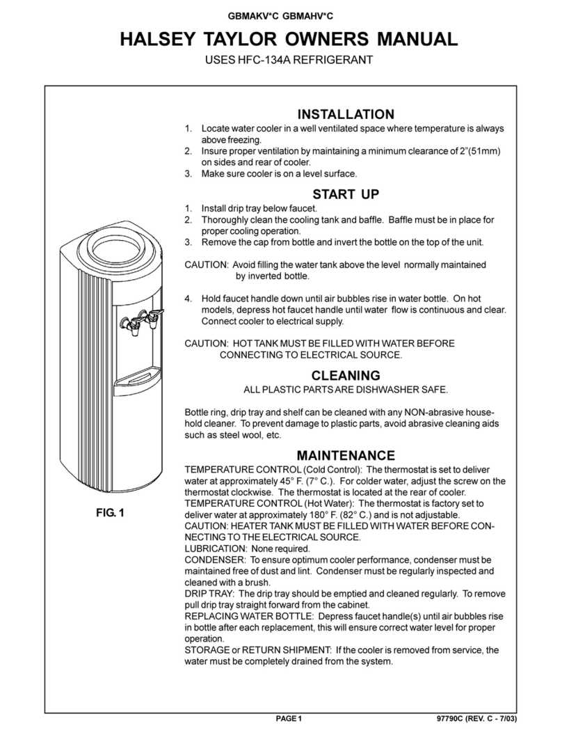
Halsey Taylor
Halsey Taylor GBMAKV*C owner's manual
Halsey Taylor
Halsey Taylor WM8 Series owner's manual

Kenmore
Kenmore Elite 625.386200 Use & care guide
Apec Water
Apec Water RO-PH90 Installation instructions & owner's manual
First Sales
First Sales PDIM24 Installation instructions and owner's manual

Clean Water Systems
Clean Water Systems Fleck 5600-SXT Installation and startup guide

National
National NC-30HN operating instructions
AOX
AOX AOX-3900 ESVT user manual
Pentair
Pentair PRF34K installation instructions

Escowa
Escowa UNDERCOUNTER Installation, user and maintenance manual

LF
LF Millennium Instruction and maintenance
