Agilis Jettenders 330 User guide
Owner‘s Handbook
Agilis Jet Tenders
Lohfeldstr. 2
D-52428 Jülich
GERMANY
ofce: (+49) 2461 - 340 33 30
fax: (+49) 2461 - 340 33 313
www.agilis-jettenders.com
305 - 330
Welcome to Agilis Jettenders!
Welcome to Agilis Jettenders! And thank you for choosing our product!
We have conceived this handbook to give you enough information while at sea. This way we are
sure you will enjoy your ride safely.
The content of this handbook will inform you about the equipment, its operation and maintenance.
It is very important that you read it and familiarise yourself with the boat.
Please note that this jet uses water jet propulsion. Be aware that maneuverability decreases while
decelarating. Handling and operating experience, as well as knowledge of seamanship is
compulsory (please refer to RYA Level 2 or ICC).
At delivery, your Agilis authorized dealer will guide you through the functions and features of the
boat. Do not forget to ll your warranty registration form with the boat‘s CIN. This handbook should
be kept in a secure place and handed over to the next owner.
Your safety is our priority. Therefore we ask you to comply with the safety information provided in
this handbook. Always obey the safety labels tted. Should they become unreadable, we expect
that you replace them. Local laws and restrictions are to be applied. Be aware that the inuence of
drugs and alcohol may affect your judgement.
This symbol appears on a number of labels tted to the tender.
It draws your attention to the message and refers you to the owner‘s handbook.
This safety alert symbol appears throughout the handbook and on various labels
tted to the tender. It means attention, be vigilant, your safety is involved!
Danger: situation that can result in death or serious injury.
Warning: situation that can result in death or serious injury.
Caution: situation that can result in minor or moderate injury.
To avoid personal injuries always secure loose equipment safely. Make sure that equipment
close to machineries are secured in a way that they do not fall into the engines.
Be aware of the environment. In many regions of the world, there are strictly enforced
regulations regarding the protection of the environment. It is the responsibility of the owner/
operator to be aware of applicable regulations and to comply with them.
Craft Identification Number (CIN):
INTRODUCTION

Table of Content
1. Introduction
2.General Data
2.1 Engine
2.2Classication
3. Hazards & Safety
3.1Riskofooding&stability
3.2Riskofreorexplosion
3.3ElectricalSystem-Riskofre,explosionorelectricshocks
4. Operating your tender
4.1 New Engine Break-In Period
4.2 Steering Systems
4.3 Fuelling
4.4 Check List
4.5 Accelaration & Brakes
4.6 Anchoring, mooring, towing and lifting
4.7 After use: Flushing procedure
5. General Layout
5.1 Overview
5.2 Engine Compartment
5.3FuseIdentication
5.4 Full Inspection Maintenance Table
6. Winter Storage
7. Warranty
General Data
Model
LOA
Beam
Dry Weight without options
Height
Max Speed at full load
Power
Fuel Capacity
Seating
Max Load Capacity
Design Category
305
3,05 m
1,75 m
288 kg
0,86 m
69 km/h
42 Liters
4
328 kg
C
330
3,30 m
67,1 kw / 90 hp
1,75 m
315 kg
0,86 m
68 km/h
67,1 kw / 90 hp
4
55 Liters
340 kg
C
GENERAL DATA
Engine
Engine ROTAX 900 HO ACE
Maximum
Power
Fuel
Oil Grade
Oil Capacity
Naturally aspirated 66,2 kW / 90 HP
Recommended fuel quality: Unleaded gasoline with an octane rating of at least 95 R OZ or 85 MOZ.
USA: At least “Premium 91”, unleaded
Minimum requirement: Low-quality fuel can cause loss of power and/or increase fuel consumption
Unleaded gasoline with an octane rating of at least 91 ROZ or 82.5 MOZ.
USA: At least “Regular 87”, unleaded
An increased share of ethanol can lead to premature abrasion or poor starting performance of the engine.
Use XPS 4-STROKE SYNTH. BLEND OIL
(SUMMER) (P/N 460787)
maximum 1.8 liters
Classication
Category C - „inshore“: Craft designed for trips in coastal waters, large bays, estuaries, lakes and rivers. Wind
force6andsignicantwaveheightsupto2mmaybeexperienced.
This boat complies with ISO 6185-3.
The CE plate is located in the starboard rear foot well.
TheCEplateisthecerticationtoEuropeanDirective2013/53/EU.
Technical Specications

Hazards & Safety
Risk of ooding and stability
1. Openings in the hull. (see General Layout)
2. Bilge pump.
Amanuallyoperatedbilgepumpistted.
For operating instructions see owner‘s manual of the bilge pump.
Theaudioalarmontheinstrumentpanelsignalsifbilgelevelexceeds50mm.Inthiscase:
1. Switch off the engine.
2. Open the hood to check for water.
3. Checkforoil.Inthewatercontainsoil,ONLYREMOVEMANUALLY.
4. If water is free from environmentally hazardous substances, then activate the
pump.
CAUTION Check the function of bilge pump at regular intervals.
Clear debris from the pump inlets.
WARNING: This system is not suitable for a complete draining in case of
damage.
3. Stability and buoyancy.
3.1 Position of persons and luggage.
For safe operation we recommend that your passengers sit in the middle of the boat.
Thelocationofthepassengerswilldirectlyinuencethestabilityofthiscraft.
Sitting on the sides of the boat is ALSO ACCEPTABLE as long as there is someone
sitting on the opposite side.
CAUTION While you are sailing at high speed avoid abrupt turns and
high waves as this might endanger the passengers. Make sure everybody
holds on to the safety ropes. For comfort and safety, reduce speed in waves.
Small children must sit IN the boat. Always wear a lifejacket!
When taking a sharp turn, reduce the speed of your boat. The boat will tilt
considerably inside the turning centre.
3.2 Bilge water should be kept to a minimum
3.3 Stability is reduced by any weight added
3.4 Stability may be reduced when towing
3.5 Breaking waves is a serious stability hazard
Risk of re or explosion
WARNING: Riskofre.Donotstorefuel,tanksfuellinesoranyfuel-relatedcomponentsin
direct sunlight.
1. ENGINE
Instructions for safe operation of the engine:
a) run the engine compartment fan for 5 minutes before switching on / after switching
off the engine
b) ensureowofcoolingwater
c) ensure that ventilation ducts are free
d) no smoking when refuelling and treatment of fuel spillage in craft
e) check for possible damage of fuel lines
f) avoidcontactofammablematerialswithhotengineparts
g) do not store equipment containing petrol in compartments not designed for this
purpose.
2. FIRE-FIGHTINGEQUIPMENT
2.1 FIREEXTINGUISHER
Anautomaticreextinguisheristtedintheenginecompartmentonstarboardside.
The1Kgcapacityofthereextinguishercanprotectanenginecompartmentupto1,7.Theprotec-
ted space of the boat is 1,25 .
The red light on the pilot desk blinks when:
1. thereisnotenoughpressureinthere-extinguisher.
2. there-extinguisherhasbeenactivated.
How it works:
Thepresenceofpersonnelisnotneeded.Unitinterventionisdonebysealbulbrupture.
Increaseoftemperatureduringrstperiodofre(93°)willcauseabulbbreaking,followedbythe
dischargeoftheextinguishingunit.Incaseofreinenginecompartment,theoperatorisinformedbya
red light blinking on the pilot desk. Tocheck,usereportinstalledonstarboardsideofsteeringconsole.
ChecktheengineroombypushingopentheFirePort.Incaseofre,putoutusingreextinguisher.
The boat owner/operator shall
-havere-ghtingequipmentcheckedattheintervalsindicatedontheequipment,
-replacereextinguisherifexpiredordischargedbydevicesofidenticalre-ghtingcapacity.
Responsibility of boat owner/operator
a) toensurethatre-ghtingequipmentisreadilyaccessiblewhentheboatisoccupied
b) toinformmembersofthecrewaboutlocationandoperationofre-ghting
equipment
WARNING never obstruct safety controls, e.g. fuel valves, switches of the electrical
system.
WARNING never modify any of the craft‘s systems (especially electrical, fuel) or allow
unqualiedpersonneltomodifyanyofthecraft‘ssystems.
WARNING never smoke while handling fuel.
HAZARDS & SAFETY
m3
m3

Electrical System - Risks of re, explosion or electric shocks
FireorexplosionhazardsthatmayresultfromimproperuseofelectricDCsystems:
a) battery selector switches positioned in engine compartment;
b) For description see pictures of switch panel(s);
c) Information about changing fuses can be taken from the general layout and picture indicating fuse
position, type and capacity;
d) when changing fuse, ensure that engine is not running and ignition and electricity circuit
is OFF.
e) recharging of batteries controlled by automatic voltage sensitve switch:
when disconnecting/reconnecting battery check proper „+/-“ connection.
WARNING never work on the electrical installation while the system is energized.
WARNING never modify the craft‘s electrical system or relevant components.
Installation, alterations and maintenance should be performed by a competent
technician.
WARNING never alter or modify the assessed current amperage of overcurrent
protective devices.
WARNING never install or replace electrical appliances or devices with components
which exceed the rated current amperage of the circuit.
WARNING never leave the craft unattended with the electrical system energized,
exceptautomaticbilgepump,reprotectionandalarmcircuits.
Risk of falling overboard
Should a member of the crew fall overboard, turn the steering wheel to move the propeller away from
the person. Turn off the engine when the person is alongside the vessel and throw him/her a line/lifebuoy/
ladder.
Theyshouldberecoveredusingthexedboardingladderttedtotheboat‘stransom.
HAZARDS & SAFETY

Operating Your Tender
New Engine Break-In Period
NOTICE
Continued wide open throttle runs and
prolonged cruising without speed variations
should be avoided.
This can cause engine damage during the
break-in period.
Abreak-inperiodof10hoursisrequiredbeforecontinuousoperationatfullthrottle.
Amaximumof3/4throttleisrecommendedtoachieveagoodbreak-in.Briefaccelerationandspeedvariations
provide a good break-in.
Steering Sytems
Installedsteeringsystemdesignedexclusivelyforjetboatsfeaturingaarcangle135°locktolock,aspecial
steering cable plus an assortment of mounting options.
Scheme showing parts:
1. Pivot-conduittting
2. Bushing for cable cond. ftg. Pivot
3. Pivot - cable terminal end
4. Bushing for cable term. end pivot
Helm Cable Bracket Hardware Kit
5. Locknut(3/8-24)-conduitttingpivot
6. Lock Washer for 3/8-24 Locknut
7. Locknut (1/4-20) - cable terminal end pivot
8. Lock Washer for 1/4-20 Locknut
9. Hex Bolts (anti-vibratory patch) - bracket
Fuelling
Your new vessel has been thoroughly checked and tested, as well as drained fo fuel prior to delivery.
Please follow these steps when fuelling:
Step 1: Switch off the engine.
Step2: Removetheseatcushioninordertoaccessthellercap.
Step 3: Re-fuel in a ventilated area.
Step4: Donotoverllthetank;also,donotspillfuel.
Step5: Closethefuelcaprmlywhennished.
THEAREAAROUNDTHEFUELFILLERSHOULDNOTBEWETASWATERMAYENTERTHEFUEL
TANK.
CAUTION: NEVER USE FUEL CONTAINING ETHANOL
UseoffuellabeledE15isprohibitedbyUSEPARegulations.
1
2
7
8
3
4
9 (3 Required)
5
6
OPERATING YOUR TENDER
Steering Wheel Removal
CAUTION: DO NOT REMOVE WHILE OPERATING
Step 1: Hold your steering wheel centered from both sides.
Step 2: Pull the quick release to unlatch the steering wheel then pull towards you.
Step 3: To attach the wheel, hold it centered above the shaft and gently push down
until it locks.
NOTE: Grease the mechanism every two weeks and before winter storage

Check List
Caution:Tubesmustbeinatedinthecorrectsequencetopreventover-inationBefore Use
1
1.1 Setvalvesto„closed“andinatetubesevenly,startingatrear/right,rear/left,thenforward
valves.
1.2 Check bilge for fuel or water contamination.
1.3
1.4
1.5
Tighten footwell drain plugs.
Check bilge for fuel or water contamination.
Ensure towing valve is set to open position.
Check that engine cover latches are secure.
The engine must be at operating temperature before an accurate level is indicated on
the dipstick
Oil Level
Check
2
2.1 The oil level should be between MIN and MAX on the dipstick as shown below.
2.2 Do not screw cap into check level.
2.3
2.4
Usethecorrectgradeofoil.(Recommended0W40fullysynthetic)
Donotoverll.
Safety
Check
3
3.1 WARNING: ALWAYS attach the safety lanyard to your leg when engine is running. As a safety
check, test the lanyard for its functionality by pulling it away from its seating - the engine
should stop.
3.2 WARNING: NEVER operate the boat when bathers are using the boarding ladder. The reverse
deectormightcauseseriousinjury.
3.3
2.4
WARNING: NEVER investigate the engine compartment while the engine or the ignition is on.
Donotoverllanyuids.
Check List
Make sure to start your boat in a water depth of minimum 0.9 m /3 ft.Starting
your Boat
4
4.1 Turn on the battery isolator.
4.2 Run engine room blower for 5 minutes.
4.3
4.4
4.5
Secure any loose ropes that could get sucked into the jet unit.
Ensure the shift lever is in neutral position.
Connect the safety lanyard to your leg/body.
WARNING: Personal injury may result if lanyard is not attached!
4.6 Press the ignition button until the engine starts. 1. Battery isolator switch.
2. Keyswitch.
Note:Atleast10secondsshouldbegivenbeforeturningoffthebatteryisolatoraftertheenginehasbeen
switchedoff.NoncompliancewillresultindatalosswithintheenginesECU.
MIN MAX DO NOT THREAD IN TO CHECK!
operating
range
OPERATING YOUR TENDER

Anchoring, mooring, towing and lifting
CAUTION Always tow or be towed at a slow speed. Never exceed the hull speed
when being towed.
CAUTION A tow line shall always be fastened in a way that it can be released
when under load.
The owner/operaor of the boat should ensure that mooring lines, towing lines are
adequate for the vessel‘s intended use.
The craft is equipped with the following strong points:
Item Location Strength, kN (kg)
3MooringCleats seeGeneralLayout 7(700)
1TowingEye ForesideStern 8,5(850)
The owner is responsible for using adequate mooring lines, towing lines and anchor chain and lines.
Thebreakingstrengthofthelinesusedshallnotbemorethan80%ofthebreakingstrengthofthe
associated strong point.
The crew needs to familiarize themselves with the equipment.
TOWING VALVE
CAUTION:Engineoodingmightoccur.Towingvalvetted.
Valve must be in CLOSED (lever vertical) position during towing and
OPEN (lever horizontal) position during use.
Failure to observe correct valve position will result in
serious engine damage.
TOWING VALVE
OPEN FOR
RUNNING TENDER
CLOSED FOR
TOWING TENDER
After Use: Flushing Procedure
Itismandatorytoushengineofsaltwaterafteruseandpriortostorage.Failuretocarryoutushingwill
signicantlyreducethelifeofenginecomponentsandmayinvalidatewarranty.
DO NOT operate throttle out of water.
It is also advised to thoroughly wash the jet pump area with fresh water to remove all salt residues.
CAUTION:EngineMUSTbeonbeforewaterisconnected.Riskofengineoodingexistsifwater
remains on after the engine has been switched off.
1. Connectafreshwaterhosetotheushingattachmentcoupling.Pressouterringtoengageand
release adaptor.
2. Start engine.
3. IMMEDIATELY turn the water supply on.
4. Runengineatidleforapprox.1minutetocompletelyushtheopenloopcoolingsystem.
5. Turn off water supply.
6. Allowtheenginetorunfornolongerthan10secondstoallowwatertoexitthecoolingsystem,then
turnofftheengine.Disconnectthehoseformthetheushingattachment.
7. Check bilge of boat and dry any residual water. Remove footwell drain plugs.
Accelerate & Brakes
Thethrottle/gearleversarettedontherighthandsideofthesteeringwheel.
Theleft(red)levercontrolsthethrottlefrom0(leverdown)to100%(leverup).Therightleverhas2positions:
1. Middle (Forward / Neutral)
2. Down (Rear)
To move forward, the right lever has to be in the middle position. To engage the forward gear, gently push the
left (throttle) lever forward. This will move the craft forward. The throttle lever controls the speed.
Pushing the right lever down will engage the brake. In order to stop the craft, hold the right lever down and set
thethrottleto0%.Whenthecrafthascometoastop,movetherightleverbacktothemiddleposition.This
will engage the neutral gear.
For further information contact your authorized dealer.
1. Start / Stop Button
2. Bilge Pump Buzzer
3. Fire Extinguisher Alarm Button
4. Throttle Lever
5. Gear Lever
5
3
2
1
4
OPERATING YOUR TENDER

General Layout
1. Front step-plate with rope roller and navigation lights
2. „Push-down“ mooring cleat
3. Front seat (splash-water-resistant locker under seat)
4. Front / Rear lifting points
5. Front foot well drain
6. Strap handles
7. Seat(fueldeckllerunderneath,starboardside)
8. Side step plates
9. Engine compartment cap with white all-roung light
10. Aft foot wells drains
11. Aft lift points
12. Pilot seat
13. Grab rails
14. Towing ring
15. Swimming platform (foldable retract)
16. Aft step plates
17. Drain plugs
18. Drainskinttings
19. Flushing connector
20. Bilge pump outlet
21. Tie-down rings
22. Retractable ladder
23. CraftIdenticationNumber
24. Depth Transducer
23
21
22 20
17 17
19
21
18
330
305
23
21
21
17
17
22
19
18
24
GENERAL LAYOUT
12
3
4
4
65
7
8
8
9
10
10
11
11
12
13
13
14 15
16
16
NOTES:
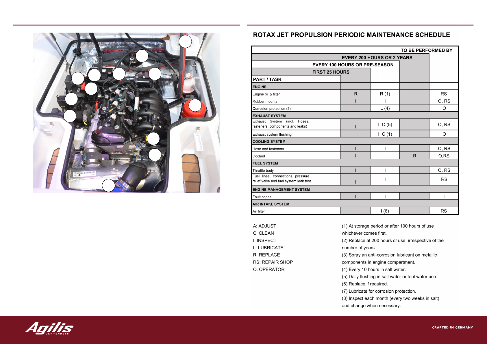
Engine Compartment
3
1
6
5
4
11
8
12
10
9
7
2
3
1. Towing Valve
2. MainCircuitBreaker(50amp)
3. Battery Switch
4. Service Battery
5. Bilge Pump
6. Fuel Tank
7. Deck Filler (fuel)
8. Engine Air Filter
9. EngineBattery
10. OilDipstick
11. GasFireExtinguisher
12. Engine Oil Filter
GENERAL LAYOUT
Full Inspection Maintenance Table

Winter Storage
Due to temperature changes and humidity, the boat has to be stored in a dry and aerated place.
Buoyancy Tube:
Beforestoringyourboat,deateandrinsethetubesthoroughlytoremovealldebris.Leavetodrybefore
polishing.Thetubesshouldbestoredslightlyinated.
Battery:
Thisboatusesawetcellbattery.WhenstoringtheboatforWinter,disconnecttheearthterminal.Usean
accumatetoextendbatterylife.
Fuel System:
Fillthetankcompletelybeforestorage.Useafuelstabilizertominimisefuelbreakdown.
Cables:
All control cables should be greased at both ends.
Cooling System: Proceed as in chapter Flushing Procedure to remove debris that may be found in the raw
watercoolingcircuit.Checktheanti-freezecontentoftheenginecoolant.Usefrostprotectionsuchasdistilled
watermixedwithpropyleneglycoltoa1:1ratio.Usethesamemixtureintheopenloopsystem.
Engine Oil:
The engine oil should be changed prior to storage. Leaving used oil in the engine for longer periods may cause
corrosion.
Cylinders:
Approximately10mlofcleanengineoilshouldbelledintoeachsparkplug.Starttheengineafewtimes
before screwing back the spark plugs.
Hull & Deck:
Thedeckshouldbecleansedonaregularlybasis.Useamilddetergentandwarmwater.Rinsethoroughlyto
removedebris.BothhullanddeckshouldbepolishedregularlytoprotectfromUVchalking.
Corrosion Protection:
White grease, i.e. Vaseline, should be applied to the battery isolator switch, upholstery press studs and the
running light pole base. Spray the key switch with a maintenance spray. Engine, electrical connections, helm,
and jet pump area should be maintained with corrosion guard.
WINTER STORAGE

Agilis Warranty
Ourwarrantycoversyourboatfor2yearsor60hoursfromthedateoftheoriginalregistration.
On purchasing a craft, Agilis provides you with with the original registration card. This card should
belledandsentbacktoAgiliswithin30daysafterregistration.
Agilis guarantees to the original purchaser that all seams of the ination valves, tubes and the
fabricusedtoconstructthetubeswillbeawlessoveraperiodof3yearsfromthedateoforiginal
registration.
Forcommercialuseourwarrantycoversyourvesseloveraperiodof4monthsor60hoursfromthe
original date of registration. Agilis warranty is limited to repairing or replacing defective parts.
AgilisWarrantyDOESNOTCOVERnormalwearandtear,anyminorboatdamage,tubesexposed
to corrosive chemicals, parts installed by third party personnel, boats purchased for commercial or
governmental use, defects caused by non-adherence to instructions.
The warranty claim must be approved in writing by Agilis Jet Tenders. The original owner must send
awrittennotication,acopyofhisreceipt,aphotographofthedamageto
Agilis Jet Tenders, Lohfeldstr. 2, 52428 Jülich, Germany
ofce:(+49)2461-3403330
fax:(+49)2461-34033313
Afterapproval,Agiliswillsendawrittennoticationtotheownerwheretosendtheboatforrepairor
replacement. Repairs will either be taken place by authorized dealers or Agilis Jet Tenders.
Agilis Jet Tenders do not guarantee any work carried out by unauthorized personnel.
All parts replaced under this Warranty become the property of Agilis Jet Tenders.
WARRANTY

Notes
NOTES
We hope that this handbook will help you getting started with your new vessel. It has been
conceivedtobecompactsothattheimportantchaptersareeasytond.
In case you need more support, do not hesitate to contact your authorized dealer or
Agilis Jet Tenders for any inquiries.
We wish you a pleasant trip !
This manual suits for next models
1
Table of contents
Popular Boat manuals by other brands


Rinker
Rinker Cruisers Owner's/operator's manual

Wave Sport
Wave Sport WHITEWATER owner's manual

KAYACAT
KAYACAT PUMA Assembly instructions

Pro-Line Boats
Pro-Line Boats 2010 35 Express owner's manual

KL Industries
KL Industries WaterWheeler ASL Electric owner's manual

Grand
Grand GOLDEN LINE G340N owner's manual


