agri supply PTOW3 User manual

PTO WATER PUMP
OWNER¡S MANUAL

TABLE OF CONTENTS
Description 1
General Safety Information 2
Specifications 3
Installation 3
Operation 4
Maintenance 6
Troubleshooting 9
Explosive view&parts list 10

1. Description
The equipment is designed for the purpose of sucking water for field irrigation .The PTO
water pump is designed to be driven by the power takeoff mechanism of a suitable tractor, via
power takeoff (PTO) drive shaft.
WARNING: Please read and save the Owner¡s Manual. Read carefully before attempting to
install, operate or maintain the product described. Protect yourself and others by observing all
safety information. Failure to comply with instructions could result in personal injury and/or
property damage! Retain instructions for future reference.
FEATURES
・3600RPM
・COMPACT DESIGN
・Driven by the power takeoff mechanism of a suitable tractor
・3INCH.4INCH.6INCH
・
Figure 1 - PTO Water pump

2. General Safety Information
Study these SAFETY RULES carefully before installing, operating or servicing this equipment.
Become familiar with Operating Instructions and with the water pump. The water pump can
operate safely, efficiently and reliably only if it is properly installed, operated and maintained.
Many accidents are caused by failing to follow simple fundamental rules.
DANGER: Indicates an immediately hazardous situation which, if not avoided, will result in
death or serious injury. Danger is limited to the most extreme situations.
WARNING: Indicates a potentially hazardous situation which, if not avoided, could result in
death or serious injury.
CAUTION: Indicates a potentially hazardous situation which, if not avoided, may result in minor
or moderate injury. Caution may also be used to alert against unsafe practices.
NOTE: Indicates a statement of company policy as the message relates directly or indirectly to
the safety of personnel or protection of property.
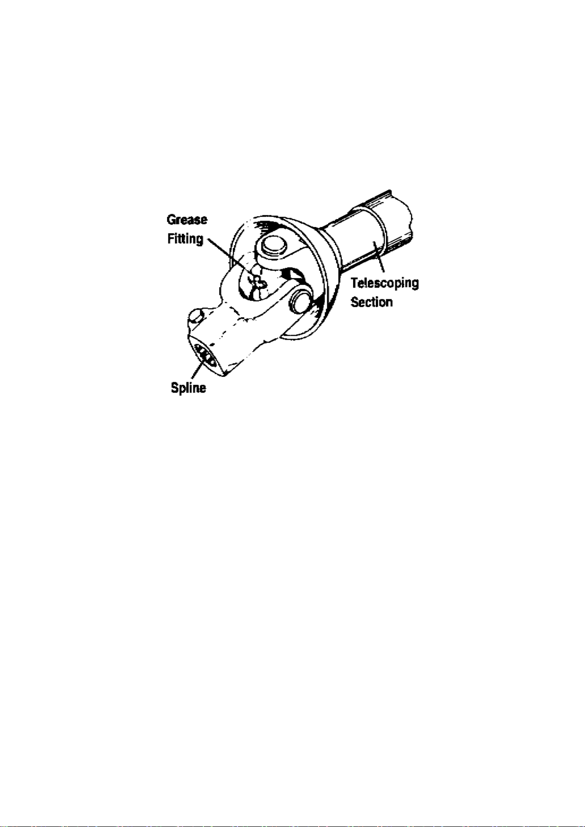
1. Exposed PTO shaft is dangerous. Provide safety guards around it.
2. Do not work on this water pump (or other potentially hazardous equipment) when tired or
fatigued.
3. Tractor engines used to drive the water pump give off DEADLY carbon monoxide gas through
their exhaust systems. This dangerous gas, if breathed in sufficient concentrations, can cause
unconsciousness or even death. Operate prime mover only in open areas where sufficient
ventilation is available. NEVER operate the engine inside any room or enclosure where exhaust
gases might accumulate and endanger people.
4. Read and make sure you understand all safety precautions and warnings in this manual and
on tags and labels affixed to the water pump.
5. Keep a fire extinguisher near the water pump. Keep the extinguisher properly maintained, and
be familiar with its proper use.
6. We cannot anticipate every possible circumstance that might involve a hazard. The warnings
in this manual and on the water pump are, therefore, not all inclusive. If a procedure, work
method, operating method, or technique not specifically recommended by us is used, you must
satisfy yourself that it is safe. for you and others and that the water pump or property will not be
damaged by the procedure or method you choose.
Unpacking
Before first using the unit, completely remove the water pump from the shipping package, and
from the shipping pallet or skid to which it might be attached. In addition, completely remove all
shipping material from the water pump.
Inspection
The water pump set was inspected and tested before it was shipped from the factory. When
unpacking the water pump, be sure to inspect it carefully for freight loss or damage. If loss or
damage is noted at the time of delivery, require that the person making the delivery note the loss
or damage on the freight bill, affix the carrier's signature under the consignor's memo of the loss
or damage.

3. Specifications
Water pump PTOW3 PTOW4 PTOW6
Outlet size(inch) 3 4 6
Itlet size(inch) 3 4 6
Speed(rpm) 3600 3600 3600
Flow(m3/h) 60 80 200
Lift(m) 28 25 15
Suction(m) 7 7 6
Power Needed(Hp) 15-125 or more 25-125 or more
PTO Drive Speed(rpm) 540 540
PTO Shaft 1-3/8" spline, 6-spline
Gearbox Reduction single stage
Ratio PTO Shaft to Revolving Field Speed 1 to 6.67
Recommended Gear Box Oil SAE 90 Gear lube Oil
PTO Shaft Lubricant Lithium base grease
4. Installation
INSTALLING THE PTO SHAFT
The water pump gearbox features a standard 1-3/8 inch diameter, 6-spline drive shaft. Supply a
suitable power takeoff (PTO) shaft to fit the gearbox shaft and the tractor PTO drive shaft.
Connect power takeoff (PTO) shaft guard onto gearbox shaft. Keep water pump and tractor
shafts parallel as viewed from above and from the sides of the shafts. Maintain PTO shaft joint
angles equal and as small as possible (Figure 2).
For Smoothest Operation Keep Tractor Shaft and Gearbox Shaft Parallel (Side and Top Views).
Keep Joint Angles Equal & Small as Possible.
Figure 2 -- Checking PTO Shaft Connection
DANGER: Never operate the water pump until the PTO shaft guard has been properly
installed. Serious injury can result from operating the water pump without the shaft guard in
place.

INSTALLING THE CONNECTOR PANELS(OPTIONAL)
According to the types of tractor, the connector panels are optional. As shown in Figure 3.
Figure 3 ¨ Installing The Connector Panels(optional)
GEARBOX LUBRICATION
Before operating the water pump set, check gearbox oil level as outlined in "Maintenance"
section on page 10.
CAUTION: Operating the water pump with low gearbox oil level may cause gearbox failure.
See "Maintenance" section on page 10 for more information on periodic maintenance.
5. Operation
This section outlines basic procedures for operating water pump set. Read instructions carefully.
Also read all information and instructions in Installation sections as well as General Safety
Information.
DANGER: Comply with all safety rules, read all warning and caution decals and tags affixed to
the water pump. Failure to obey safety rules may result in personal injury or death.
BEFORE USING YOUR WATER PUMP
WARNING: This water pump requires a certain horsepower to drive when full capacity loads
are being powered through unit. This horsepower is applied to water pump as torsional or
twisting force. Such a high twisting force can tip over water pump with considerable force as
soon as you apply water suction. This could cause personal injury or damage to equipment.
1. Use ONLY a 540rpm power takeoff drive operating speed. Any attempt to operate the water
pump set with higher power takeoff speeds will result in damage to equipment or personal injury.
2. Make sure the water pump fill full water before starting and has been properly prepared to
use
CHECK GEARBOX OIL LEVEL
Before using the water pump, check gearbox oil level. See "Maintenance" section on page 10.
CONNECTING THE POWER TAKEOFF SHAFT
Connect the PTO shaft to the tractor PTO drive system and to the water pump's gearbox shaft.
The shaft must be fully engaged with both the tractor and the water pump shaft. The water

pump and tractor shafts must be parallel as viewed from the top and sides of the shaft. Maintain
PTO shaft joint angles (Figure 2) equal and as small as possible.
For Smoothest Operation Keep Tractor Shaft and Gearbox Shaft Parallel (Side and Top Views),
Keep Joint Angles Equal & Small as Possible.
CAUTION: Make sure the water pump's PTO shaft guard is properly attached to the gearbox
before starting.
6.Connect hose

7. Fill priming water
WARNING:Not allowed start water pump if water pump is not fill water fully. Not allowed
start water pump if Gearbox box is not fill to proper oil level.
STARTING THE WATER PUMP
Follow these steps to start the water pump:
1.Fill water full to water pump.
2.Fill oil to proper level to gearbox
3. Start the tractor engine
4.Choose correct gear and engage the power takeoff (PTO) drive.
5. Slowly increase tractor engine speed while observing water pump running till pump out
water,adjust engine speed to rated speed.
STOPPING THE WATER PUMP
Follow these steps:
1. Release the cluth, Let tractor engine run for a few minutes at no-load, to cool internal parts.
2. Shut OFF the tractor engine.
3. Clean water pump
4. Remove the power takeoff (PTO) shaft from water pump and tractor.
8. Maintenance
Your water pump set will perform reliably only if you properly maintain it. This section outlines
the minimum recommended periodic maintenance to keep your unit in good condition and
increase its life. If operating your water pump under extremely adverse conditions (extreme dust,
dirt, cold or heat), increase periodic maintenance frequencies accordingly.
VISUAL INSPECTION
Carefully inspect the water pump set before you first use it and at least once each month
thereafter. Look for the following discrepancies:
1. Loose or broken parts
2. Defective connections
3. Missing, corroded or damaged fasteners and other hardware
4. General appearance and cleanliness

CLEAN THE WATER PUMP
Keep the water pump set clean and free of foreign material. Please check pump after water pump
stop on each time and clean pump if pump with foreign material.
CHECK GEARBOX OIL LEVEL
Check gearbox oil level before you first use it. Thereafter, check gearbox oil level every 10 hours
of operation or once weekly, whichever comes first. To check oil level, proceed as follows:
1. Make sure the water pump is as level as possible.
2. Remove the OIL LEVEL CHECK PLUG from the water pump gearbox (Figure 6).
Figure 6 -- Gearbox Oil Servicing Points
3. Check oil level. Oil should be at point of overflowing the OIL LEVEL CHECK PLUG opening.
If necessary, add SAE 90 GEARLUBE oil to the recommended level. See "CHANGE GEARBOX
OIL."
4. When oil level is correct, install and tighten the OIL LEVEL CHECK PLUG.
CHANGE GEARBOX OIL
Change gearbox oil after the first 25 hours of operation. Thereafter change gearbox oil every 250
operating hours or every six months, whichever occurs first. To change gearbox oil, proceed as
follows:
1. Operate the water pump until gearbox oil is thoroughly warmed up (about 30 minutes), then
shut down.
2. Immediately after shutting it down, remove gearbox oil drain plug (Figure 6). Drain oil
completely into a suitable container. Remove oil fill/breather and oil level check plug to facilitate
draining.
3. After all oil has drained, install and tighten oil drain plug.
4. Add SAE 90 gearlube oil through oil fill/breather opening, until oil just starts to overflow from
oil level check plug opening. Pour slowly.
5. When oil level is correct, install and tighten oil fill/breather and oil level check plug.

6. Recheck all plugs. Make sure they are tight.
7. Start water pump and check for leaks.
LUBRICATE POWER TAKEOFF (PTO) SHAFT
Grease the PTO shaft frequently. Use a low pressure, grease gun filled with general purpose,
lithium base grease to apply to grease fittings (Figure 7) at shaft universal joints. Also apply
general purpose, lithium base grease to PTO shaft splines and to telescoping sections of shaft.
Figure 7-- Grease Points to Power Takeoff Shaft

9. Troubleshooting
Symptom Possible Causes Corrective Action
The pump can not do
pumping
1. Fill water is not enough
2. Inlet pipe leakage
3. Speed of pump is too low
4. The filter net is obstructed
1. Refill water into the pump
2. Check inlet pipe and connector of
pipe. change pipe or tighten the
screw
3. Check connection of all parts,Keep
clutch release and so on.
4. Check and clean up
The flow of water is not
enough
1. The filter net ,pipeline or
impeller is obstructed.
2. Speed is low
3. Impeller or seal is wore
seriously
4. Inlet pipe leakage
1. Clean up the obstructed
2. Increase speed
3. Adjust the gap or shange impellr
and seal
4. Check inlet pipe and connector of
pipe
The flow of water is not
well-distrbuted and
sometimes large ,sometimes
small
1. The is air in the pump or inlet
2. Speed is not stability
1. Screw off air drain screw cock,and
eliminate the air.Check the pipeline
or change machinery
2. Adjust the speed of engine
Power consumption of pump
is too large
1. There is a rub between impeller
and flow guidance
2. The impeller is obstructed by
weeds or foreign matters
1. Listen to the sound
carefully,whether the impeller is
clashed with the case and then to
adjust.
2. Check and clean up.
No flow suddenly 1. The connector of inlet pipe is
loosed or leakage.
2. Suction head is too high
1. Check inlet pipeline and remedy.
2. Check suction head and low the
position of pump
Cause vibration or noise
1. Suction head is too high and
cause vibration.
2. Out water is too large.
3. Inlet pipe is obstructed by
foreign body so the resistance is
too large.
4. Rotary part is loosed
5. Installing for pump unit is not
stability.
6. There is air lay up in the pump
or pipeline.
7. Impeller damage
1. Check suction head and lower the
position of pump.
2. Decrease the output of water.
3. Check inlet pipe and filter net to
clean up.
4. Listen carefully and inspect the part
which cause the noise and stop the
machine to adjust.
5. Stop the machine for checking and
adjusting.
6. Screw off air drain screw cock and
eliminate the air.
7. Stop the machine for checking and
change the impeller with a new one

10.Parts Diagram
This manual suits for next models
2
Table of contents
Popular Water Pump manuals by other brands

Zgonc
Zgonc YELLOW GARDENLINE NEW GENERATION YGL N.G.... Translation of the original instructions

Armstrong
Armstrong LIFT NT25 installation instructions

Enerpac
Enerpac PC-115 instruction sheet

Grundfos
Grundfos SCALA1 instructions

Wilden
Wilden Original P8 Engineering, operation & maintenance

Binks
Binks DX200AR Service manual

Flotec
Flotec FP400C installation instructions

IWAKI PUMPS
IWAKI PUMPS ES-B Series instruction manual

Kessel
Kessel Aqualift F XL Duo Instructions for installation, operation and maintenance

Nittoh
Nittoh UP-35RH-NC Operation and maintenance manual

Veichi
Veichi SI21 manual

Oerlikon
Oerlikon GCB51K operating instructions