AGT PSG BCR04 Guide

BCR04
Sam
p
le Gas Cooler
Installation Manual
Operating Manual
Maintenance Manual
Spare Part List

Installation-, Operating-, Maintenance-Manual, Spare Part List BCR04
AGT-PSG GmbH & Co.KG
Errors and printing mistakes excepted
Page 2
Translation - Manual BCR04 Rev. 6/2017
Model / Type
EG Declaration of Conformity and
CE Marking
Manufacturer: AGT-PSG GmbH &Co.KG
Richard-Lucas-Straße 6, 41812 Erkelenz, Germany
Product: BCR03 Sample Gas Cooler
Model-/Artikelnumber BCR03-xxxx-x-xx-x
The sample gas cooler is developed, designed and manufactured
following the guidelines 2006/42/EG (machines), 2014/35/EU
(low voltage guideline), 2014/30/EU (EMC), 2014/68/EU
(pressure equipment) and 93/68/EWG (CE-marking guideline). It
corresponds to the essential requirements of these guidelines.
The following harmonized standards in actual revision have been
used:
DIN EN ISO 12100-1 /-2, security of machines
EN 983, security of pneumatics
EN 378-1 bis 4, refrigerant plants and heat pumps
EN 60335-2-34, electrical security engine compressors
EN 61326-1, EMC general requirements
EN 61000-6-2, EMC interference resistance
EN 61000-6-4, EMC interference emission
EN 60204-1, electrical equipment for industry machines
The following national standards and specifications are used:
BVG D4, refrigerant plants, heat pumps and cooling units
A technical documentation is completely present with the manual.
Erkelenz, 08.05.2017
JochenPodiwin
ManagingDirector

Installation-, Operating-, Maintenance-Manual, Spare Part List BCR04
AGT-PSG GmbH & Co.KG
Errors and printing mistakes excepted
Page 3
Translation - Manual BCR04 Rev. 6/2017
Introduction
Dear Customer,
Thanks that you have decided to buy our BCR03 sample gas cooler. You have chosen one of the most
progressive appliances, which will facilitate a durable and trouble-free operation, if installation and
operating is correct.
Before installation and initial operation, please read the following instructions very carefully
and follow our indications! Only if you observe our regulations and instructions for the
sample gas cooler, a perfect functioning and so, a reliable compressed air conditioning will
be guaranteed. Installation and initial start of operation has to be done through qualified and
skilled staff only, and under usual proceedings within the gas analysis technology. Here from
resulting general rules for the proper installation and operation could possibly not be taken
completely into this instruction. We are not liable for non appliancespecific regulations and
instructions. If statements in this instruction are contrary to legal or other valid regulations,
so they have to be replaced accordingly. Other statements remain untouched. Due to the
continuous technical evolution, we reserve the right to introduce any necessary change
without giving previous notice.
This manual must be maintained available in any moment for future references and
it has to be intended as inherent part of the sample gas cooler.
These operating instructions must be continuously available at the site where the sample gas
cooler is used. We recommend to prepare a copy and keep the same in a safe and freely
available place next to the sample gas cooler. Keep the original document in a safe place.
Notes on supplementary documents: Supplementary documents such as operation manuals
for options or pertaining components must always be heeded. They contain additional
information, e.g. regarding maintenance, and are therefore necessary for safe operation of
the plant.
Target Groups of these Operating Instructions
These operating instructions are intended for all persons working on and using the sample gas
cooler. We assume that all such persons are specialist personnel, e.g. electricians, analysis or
cooling technicians, respectively instructed personnel.
We assume the following points:
There are appropriate operating instructions for the application intended by the
operator.
The staff has been instructed how to handle the sample gas and is aware of the
involved risks and the general danger prevention measures.
The staff has experience in handling sample gas as well as in handling electrical and
refrigerated devices.

Installation-, Operating-, Maintenance-Manual, Spare Part List BCR04
AGT-PSG GmbH & Co.KG
Errors and printing mistakes excepted
Page 4
Translation - Manual BCR04 Rev. 6/2017
Warranty
Warranty Conditions
According to legal regulations you get a 12-month warranty concerning material defects and
manufacturing errors for this product starting from invoice date. The warranty service covers free repair
in the workshop or free replacement of the device that has been sent to the place of application free of
charge. Return deliveries must take place in suitable and sound protective packing.
Please contact directly the manufacturer AGT-PSG if the sample gas cooler fails.
Basis for all warranty claims is the purchase receipt and the undamaged model identification plate. In
case of queries we need the model type, serial number and year of construction (model identification
plate).
Damages caused through non-observance of the installation and operation instructions are not covered
through the warranty. In particular from the warranty are excluded: Wear parts and operating supplies,
damages caused by improper installation, damages cause by improper use or overload of the cooler,
damages cause by lack of service, damages caused by events, which are not within the sphere of
influence of the manufacturer.
Tampering the safety and security devices is not permissible. Only skilled workers of the
manufacturer are authorized to work on the cooling system. In the case of warranty claims
the sample gas cooler has to be in its original condition.
Purpose of Use
Proper Use of the Sample Gas Coole
r
The sample gas cooler is used in the sequence of sample gas conditioning, wherein cross-sensitivity may
not be observed in case of analyzers due to low and constant dew points. At no subsequent point does
the dew point decrease. The analyzer is protected from the moist sample gas.
WARNING! Improper use! The purpose of the machine is the cooling of sample gas as well
as the separation and discharging of condensate. If you use the sample gas cooler for other
purpose or other media, any warranty of the manufacturer will expire. This sample gas cooler is
not suitable for the treatment of dirty gas or of gas containing solid particles.
CAUTION! Toxic and explosive gases! Corresponding guidelines must be adhered to while
operating with toxic and explosive gases.

Installation-, Operating-, Maintenance-Manual, Spare Part List BCR04
AGT-PSG GmbH & Co.KG
Errors and printing mistakes excepted
Page 5
Translation - Manual BCR04 Rev. 6/2017
Important Advices
General
This manual contains indications and instructions about the operation and service of sample gas coolers
under consideration of safety instructions. Depending on gas flow, inlet temperature, inlet dew point and
ambient temperature, the sample gas cooler can achieve a dew point between 2°C and 10°C.
Local and national rules for accident prevention must be noticed! The rules for disposal of condensate
have to be observed. In case of non observance of the safety devices and the indications in this operation
instruction, the producer is not liable. This is applicable for the operation as well as service and
maintenance of sample gas cooler, even though this operation instruction does not explicit refer to it.
Interventions into safety devices are not allowed. During the warranty period, only skilled workers of the
producer are authorized to work on the refrigeration system. After this, through well experienced staff
according DIN EN 378.
The operator of the sample gas cooler must keep it in good condition, operate it correctly, monitor and
maintain it regulary.
Safety Indications
DANGER! Supply voltage! Only qualified personnel are authorized to maintain and to
operate electrically powered devices. Before attempting maintenance, the following pre-
conditions must be satisfied: Ensure that main power is off, machine is locked out, tagged for
service and power cannot be restored during service operations.
DANGER: Explosive Area! This sample gas cooler should not be operated in explosion-prone
areas.
WARNING! Unauthorized interference! Warranty does not apply to any unit damaged by
accident, modification, misuse, negligence or misapplication. Unauthorized alterations will
immediately void the warranty und guaranty. Only skilled workers of the manufacturer are
authorized to work on the cooling system.
CAUTION! Refrigerant! The sample gas cooler contains FCKW-free refrigerant fluid. Please
notice local and national rules for handling refrigerants.
CAUTION! No water! In case of fire, use an approved fire extinguisher. Never use water to
extinguish fire (or near the sample gas cooler or directly to the sample gas cooler directed
water).

Installation-, Operating-, Maintenance-Manual, Spare Part List BCR04
AGT-PSG GmbH & Co.KG
Errors and printing mistakes excepted
Page 6
Translation - Manual BCR04 Rev. 6/2017
Transport
Transport, Delivery and Storage
After arrival of the delivery, the goods must inspect immediately in regard of completeness and damage.
In the case of damage or loss, the freight forwarder has to report all details to the insurer for the
assertion of compensation. Only if an appropriate documentation (i.e. photos) is available, damages can
be claimed.
If a damage appears which could cause further damages, the customer is committed to restrict the
damages to a minimum. For damage and consequential damage which could be prevented, there is no
liability.
WARNING! Possible damage! Even when packaged, keep the machine protected from
severity of the weather. Keep the dryer always in vertical position when transported or stored.
Turning it upside down some parts could be irreparably damaged. If not in use, the dryer can
be stored in its packaging in a dust free and protected site at a temperature of 2-65°C and a
non-condensing specific humidity of 20-80%. Should the stocking time exceed 6 months, please
contact the manufacturer.
NOTICE: Recycling! The packaging materials are recyclable. Dispose of material in compliance
with the rules and regulations in force in the destination country.
If damages are discovered after initial operation, the user is committed to undertake any action
to avoid consequential damage.
First actions could be to stop the load with sample gas and to switch off the main power
connection. Unplug the sample gas cooler.
Check for visible loss or damage, if no visible damage is found place the unit near to the installation point
and unpack the contents.
It is recommended to move the still packaged unit using suitable trolleys or hoists. We advise
against any manual transport. Notice weight and dimensions of the sample gas cooler (model
identification plate / technical data sheet).
Always keep the sample gas cooler in the upright vertical position. Damage to components could
result if unit is laid on its side or if placed upside down.
Handle with care. Heavy blows could cause irreparable damage.
Only upright vertical position!
Lying horizontal position vorbidden!

Installation-, Operating-, Maintenance-Manual, Spare Part List BCR04
AGT-PSG GmbH & Co.KG
Errors and printing mistakes excepted
Page 7
Translation - Manual BCR04 Rev. 6/2017
Assembly and Installation
Installation Site
The main dimensions are shown at the dimensioned drawing of the sample gas cooler. The weight is
mentioned on the model identification plate.
Failure to install the sample gas cooler in the proper ambient conditions will affect the sample gas coolers
ability to condense refrigerant gas. This can cause higher loads on the compressor, loss of cooler
efficiency and performance, electrical component failure and cooler failure due to the following:
Compressor loss and electrical component failure. Failures of this type will affect warranty considerations.
The layout of the compact sample gas conditioner guarantees a problem-free integration into the analysis
systems.
Minimum installation requirements:
Select a clean dry area, free from dust, and protected from atmospheric disturbances. Avoid
direct solar radiation.
Minimum ambient temperature +5°C, maximum ambient temperature +45°C.
Specific humidity: 20-70%, non-condensing.
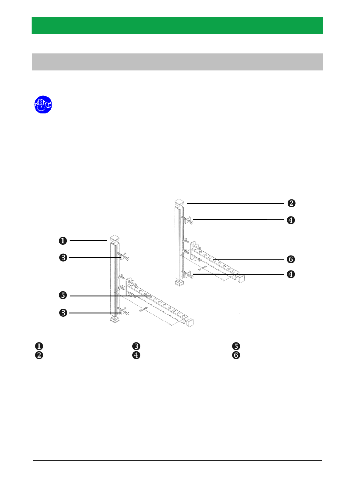
Console mounting mandatory. The mounting rails on the side panels are only for
securing against slipping on the console. Wall mounting with the rails only is not
possible.
With the mounting rails the cooler can be additionally fixed to the wall. The wall has to be perfect
vertical. Ideally you use the optional console-set of the manufacturer or a comparable
construction. The console/brackets must hold 4 times the given weights. Only use the existing
fastening points at the bottom of the housing. The dryer has to be mounted in perfect upright
position.
Ensure unhindered cooling air circulation while installing the sample gas cooler. Do not install the
sample gas cooler directly over, under or beneath possible sources of heat.
CAUTION! Ambient conditions! Do not install the cooler in areas of extreme dust and dirt or
in corrosive environment.
CAUTION! Min. 80mm free space for ventilation and bleeding! The required free space at
side- and top-plates for ventilation and bleeding the sample gas conditioner must be maintained
for smooth functioning.
Console mounting mandatory. Ideally you use the optional console-set of the manufacturer or a
comparable construction. For an operation in enclosed housings, such as analytic cabinets, we
recommend a suitable ventilation or air conditioning.
The sample gas cooler is only to lift or move at its bottom panel (2 persons needed). Handle
with care. Heavy blows could cause irreparable damage.
WARNING! Possible damage! Handle with care. Heavy blows could cause irreparable
damage.
WARNING! Possible damage! Protect the display during installation of the cooler or during
mounting work. The display is very fragile.

Installation-, Operating-, Maintenance-Manual, Spare Part List BCR04
AGT-PSG GmbH & Co.KG
Errors and printing mistakes excepted
Page 8
Translation - Manual BCR04 Rev. 6/2017
Assembly and Installation
Console-Set (optional)
All operations mentioned below to be performed by qualified personnel only.
The console-set ensures a save and stable mounting of the sample gas cooler. It is a complete set with
all needed installation and mounting materials. Notice the advices of the chapter „Installation Site“.
Fasten mounting rails 1 and 2 in perfect vertical position at the wall. The fastening points 2 und 4
need an exact distance of 400mm.
Mount the console rails 5 and 6 with identical high in horizontal position. The high itself is
variable.
Fasten the sample gas cooler on the console rails. Therefore carefully dismount the side panels of
the sample gas cooler. Bold the bottom plate together with the console rails. Therefore use the
two bores in the front area of the bottom plate. Finally remount all dismounted housing parts.
Mounting rail left Fastening points left
Console left 495mm
Mounting rail right Fastening points right Console right 495mm

Installation-, Operating-, Maintenance-Manual, Spare Part List BCR04
AGT-PSG GmbH & Co.KG
Errors and printing mistakes excepted
Page 9
Translation - Manual BCR04 Rev. 6/2017
Assembly and Installation
Feed Lines
All operations mentioned below to be performed by qualified personnel only.
As a standard, medium connections of the sample gas cooler have been designed for a 6/4mm hose. The
sample gas cooler is equipped with exactly one heat exchanger (PVDF, glass or SS316) and provides 1-2
gaspaths. The following feed lines must be connected:
Sample gas pipelines to the gas inlet connections
Analyzers to the gas outlet connections
Condensate pumps/tanks to the condensate outlet connections
Marking
Gas inlet
Marking
Gas outlet
Condensate inlet GP1 Condensate outlet GP1
Gas outlet GP1
Condensate inlet GP2 Condensate outlet GP2 Gas outlet GP2
The feed lines of the numerous possible heat-exchanger types (material PVDF/glass/SS316,
construction mono/dual, condensate connection top/bottom- see chapter “Technical Data”) may
have different designs. The picture above shows a PVDFdual-HE with condensate connections on
the top.

Installation-, Operating-, Maintenance-Manual, Spare Part List BCR04
AGT-PSG GmbH & Co.KG
Errors and printing mistakes excepted
Page 10
Translation - Manual BCR04 Rev. 6/2017
Assembly and Installation
Feed Lines
DANGER! Condensate may be toxic or corrosive! Please wear sufficient protective clothing
(for example safety gloves, face mask, safety goggles etc.).
CAUTION! Toxic and explosive gases! Corresponding guidelines must be adhered to while
operating with toxic and explosive gases.
NOTICE: Environment protection! Don’t dispose the condensate in the environment. Don’t
drain the condensate into the sewage system without treating it first. Dispose the condensate in
compliance with the local rules.
Regardless of the type of heat exchanger system (see chapter “Technical Data”) always mount
an appropriate, pneumatically tight drainage (eg. peristaltic pump, float drain, condensate tank,
etc.). For each gas path and condensate outlet a separate drain must be provided. Without
suitable condensate drainage the device will not function properly.
Lay the condensate drain line outside the device with an adequately dimensioned gradient and
without counter pressure. Avoid unwanted pipe bends and level differences as well.
If the dew point in the sample gas pipeline between the outlet probe and the sample gas
conditioner inlet falls, the sample gas pipeline must be equipped with a steam trace to avoid
condensate waste. Connect heated discharge lines to the cooler with suitable thermal
decoupling.
In case of condensation in the sample line, a suitable pre-separator needs to be installed before
the cooler. We also recommend to use a pre-separator in case of measuring points at high inlet
temperatures and high inlet dew points greater than 65°C. The capacity of heat exchangers is
thus affected favorably.

Installation-, Operating-, Maintenance-Manual, Spare Part List BCR04
AGT-PSG GmbH & Co.KG
Errors and printing mistakes excepted
Page 11
Translation - Manual BCR04 Rev. 6/2017
Assembly and Installation
Electrical Connections
All operations mentioned below to be performed by qualified personnel only.
DANGER! Supply voltage! Be sure to check the local codes in your area. The electrical
connection and the safety systems have to apply. Before connecting the unit to the electrical
supply, verify carefully the data nameplate for the proper electrical information.
WARNING! Automatic start! After you built up the electrical connections, the cooler can start
automatically.
The sample gas cooler has to be installed as shown at the circuit diagram. The cross section of the power
supply cables must comply with the consumption of the dryer, while keeping into account also the
ambient temperature, the conditions of the mains installation, the length of the cables, and the
requirements enforced by the local power provider.
Also requirements of VDE 0100 as well as relevant standards and guidelines must be adhered to while
setting up high-voltage devices with rated voltages of up to 1000V.
The local protection of the sample gas cooler is provided by the customer. The technical data is
mentioned on the model type plate and in the technical data sheet.

Installation-, Operating-, Maintenance-Manual, Spare Part List BCR04
AGT-PSG GmbH & Co.KG
Errors and printing mistakes excepted
Page 12
Translation - Manual BCR04 Rev. 6/2017
Assembly and Installation
Remote Monitoring Connection
The device has a remote monitoring option, i.e. a floating collective fault notification.
WARNING! Overcharge! Maximum rated load for the remote monitoring connection: 1,0A
Contact Strip (optional)
WARNING! Wrong connection! For special models the assignment of the contact strip can be
different. Please check the exact labeling of the contact strip before connecting components.
Conntecting the contact strip:
Contact 11-13
Operational monitoring of moisture guard 2 (optional)
Contact 9-10
Connection of external moisture guard 2 (optional)
Contact 6-8
Operational monitoring of moisture guard 1 (optional).
Contact 4-5
Connection of external moisture guard 1 (optional)
Contact 1-3
Standard operational monitoring of the sample gas cooler.
Contacts 4-8 are only active if your cooler model is equipped with an electronic control unit for
moisture guards (option). Contacts 9-13 are only active if your cooler is equipped with an
additional second electronic control unit (option).

Installation-, Operating-, Maintenance-Manual, Spare Part List BCR04
AGT-PSG GmbH & Co.KG
Errors and printing mistakes excepted
Page 13
Translation - Manual BCR04 Rev. 6/2017
Components
Condensate-Discharge/Pump (optional)
The sample gas is cooled down to +3°C in the heat exchanger. Water vapor condenses along the dew
point line as a result of the cooling. Condensate is separated from the sample gas and collected in the
condensate separator of heat exchanger. Condensate is continuously discharged by the connected
condensate pump (3,4ml/min @ 5U/min - N4,1x1,6mm).
FEATURES SR25
Self-suctioning peristaltic pump
Reliable continuous condensate removal
Synchronuous motor, gearbox with return stop
Slow speed, hose with long service life
Can operate in any installed position
Electronic Control Unit (optional)
The electronic control unit serves moisture sensors and light barriers of flowmeters and analyses their
signals. The electronic control unit is equipped with a potential-free directional contact, which triggers an
alarm notification or which switches e.g. a sample gas pump or a shut-off valve. The switch-point of the
electronic control unit can be adjusted by a potentiometer. Standard setup: Function type FS 0,5s release
delay, responsivity 75 KΩ.
FEATURES EC72.01
Control/alarm for moisture sensor
Control alarm for flowmeter light barrier
Potential-free directional contact
Adjustable switch-point
LED for operation/alarm notification

Installation-, Operating-, Maintenance-Manual, Spare Part List BCR04
AGT-PSG GmbH & Co.KG
Errors and printing mistakes excepted
Page 14
Translation - Manual BCR04 Rev. 6/2017
Components
Moisture Sensor (external / optional)
The moisture sensor protects downstream analyzers against humidity. This monitoring device reliably
signals a condensate breakthrough in case of failure of cooling devices or failure of condensate drains,
thus avoiding costly downtime and high repair costs. In case of an alarm, sample gas pumps can be
switched off and shut-off valves can be activated. The moisture sensor operates according to the principle
of electric conductivity. Its design ensures that any condensate in the sample gas flow gets directly to the
sensor surface by gravitational force. Even smallest amounts of liquid will trigger a fast and reliable
alarm. Control/alert served by an appropriate electronic control.
FEATURES MS
Protection against condensate break-through
Reliable detection of smallest amounts of liquid
Line break monitoring
High chemical resistance
Optional electronic control

Installation-, Operating-, Maintenance-Manual, Spare Part List BCR04
AGT-PSG GmbH & Co.KG
Errors and printing mistakes excepted
Page 15
Translation - Manual BCR04 Rev. 6/2017
Commissioning
General Instructions / Pre-Conditions
Pre-conditions: The sample gas conditioner is correctly mounted. The feed lines are connected. The
electrical connection is built up. Notice chapter „Assembly and Installation“!
If damages are discovered after initial operation, the user is committed to undertake any action to avoid
consequential damage. First actions could be to switch off the sample gas flow and the main power
connection.
Qualified personnel must perform the start-up. When installing and operating this equipment,
comply with all national electrical code and any applicable federal, state and local codes. Who is
operating the unit is responsible for the proper and safe operation of the cooler.
CAUTION! Exceeding of operating parameters! Verify that the operating parameters match
with the nominal values stated on the data nameplate of the cooler (voltage, frequency, gas
flow rate, gas inlet temperature, ambient temperature, etc.).
WARNING! Open housing! Never operate equipment with panels removed.

Installation-, Operating-, Maintenance-Manual, Spare Part List BCR04
AGT-PSG GmbH & Co.KG
Errors and printing mistakes excepted
Page 16
Translation - Manual BCR04 Rev. 6/2017
Commissioning
Sequence of Operations
This procedure should be followed on first start-up, after periods of extended shutdown or
following maintenance procedures. Qualified personnel must perform the start-up. The
technician who performs the start-up has to use suitable tools and has to follow all local safety
instructions and danger prevention measures.
Step-1 – Checks before initial start:
Remove packaging and material which could obstruct the area around the cooler.
Ensure that all the steps of the chapter “Assembly and Installation” have been
observed.
Ensure that the connections of the sample gas connectors and pipes are suitably fixed
and supported.
Ensure that the condensate drain pipe is properly fastened and connected to a
collection system or container.
Ensure that the sample gas feed is switched off.
Step-2 – Cooler start-up:
Model type without on/off-switch: Switch on the power supply. After switching on the
power supply the cooler will start automatically.
Model type with on/off-switch: Switch on the power supply. Then switch on the on/off-
switch of the cooler. After switching on the on/off-switch the cooler will start.
Wait some minutes until the cooler reached its operating temperature.
Step-4 – Sample gas feed:
Slowly load the cooler with sample gas. Check the connections and the piping for gas
leakage. Ensure that the condensate draining works.
WARNING! Automatic start! After switching on the power supply the cooler can start
automatically.
CAUTION! Follow system and process-specific safety measures! System and process-
specific safety measures must be followed before commissioning.
CAUTION: The number of starts must be no more than 6 per hour. The cooler must stop
running for at least 10 minutes before being started up again. The user is responsible for
compliance with these rules. Frequent starts may cause irreparable damage.
NOTICE: Temperature display! A dew point within 0°C and +10°C displayed on the control
unit is correct according to the possible working conditions (gas flow-rate, gas inlet
temperature, gas inlet dew point, ambient temperature, etc.). During the operation, the
refrigerating compressor will run continuously. The cooler must work during the full period of
sample gas feed.

Installation-, Operating-, Maintenance-Manual, Spare Part List BCR04
AGT-PSG GmbH & Co.KG
Errors and printing mistakes excepted
Page 17
Translation - Manual BCR04 Rev. 6/2017
Decommissioning
Sequence of Operations
Qualified personnel must perform the decommissioning. The technician who performs the shut-
down has to use suitable tools and has to follow all local safety instructions and danger
prevention measures.
Step-1 – Stop sample gas feed:
Slowly reduce the sample gas feed, then stop is completely.
Step-2 – Cool-down-time:
After the sample gas feed is stopped, continue with cooler operation for min. 10
minutes.
Step-3 – Cooler shut-down:
Model type without on/off-switch: Switch off the power supply.
Model type with on/off-switch: Switch off the on/off-switch of the cooler. Then switch
off the power supply.
Double-check very carefully Step-1 and Step-3. Ensure that the sample gas feed is
stopped and the power supply is really switched off.
Unplug the sample gas cooler!
CAUTION! Follow system and process-specific safety measures! System and process-
specific safety measures must be followed before decommissioning.
Dismantling
Dismantling of the Sample Gas Coole
r
If the cooler is to be dismantled, it has to be split into homogeneous groups of materials.
NOTICE! Environment protection! We recommend to comply with the safety rules in force
for the disposal of each type of material. The chilling fluid contains droplets of lubrication oil
released by the refrigerating compressor. Do not dispose this fluid in the environment. Is has to
be discharged from the dryer with a suitable device and then delivered to a collection centre
where it will be processed to make it reusable.
DANGER! Condensate may be toxic or corrosive! Please wear sufficient protective clothing
(for example safety gloves, face mask, safety goggles etc.).
CAUTION! Toxic and explosive gases! Corresponding guidelines must be adhered to while
operating with toxic and explosive gases.

Installation-, Operating-, Maintenance-Manual, Spare Part List BCR04
AGT-PSG GmbH & Co.KG
Errors and printing mistakes excepted
Page 18
Translation - Manual BCR04 Rev. 6/2017
Temperature-Monitoring and Error-Diagnosis
Digital Display/Control ST710
The digital display/control ST710 controls all the operations, the alarms and the operational setting of the
cooler. ST710 has a three-digit LED-Display, 5 buttons and 2 contact outputs.
CAUTION! Warranty lost! Any change of the original setup will lead to a total loss of
warranty.
Operation Buttons
Button UP
is for programming/setup by manufacturer.
Button DOWN
is for programming/setup by manufacturer.
Button PARAMETER
is for programming/setup by manufacturer.
Button SET
is for programming/setup by manufacturer.
Button ON/OFF/STANDBY
No function for this sample gas cooler type/model.

Installation-, Operating-, Maintenance-Manual, Spare Part List BCR04
AGT-PSG GmbH & Co.KG
Errors and printing mistakes excepted
Page 19
Translation - Manual BCR04 Rev. 6/2017
Temperature-Monitoring and Error-Diagnosis
LED-Display
2.5 Pressure dew point display during operation. Blinking display at temperature alarm.
F1L/F1H Error sensor-1: Sensor-mistake/short-circuit. Check/replace sensor-1..
EP Data loss in parameter memory (rule-contacts are dead). Switch off the dryer and
restart it.
--- Button lock active.
NOTICE: Temperature display! A dew point within 0°C and +10°C displayed on the control
unit is correct according to the possible working conditions (gas flow-rate, gas inlet
temperature, gas inlet dew point, ambient temperature, etc.). If the dew point goes under 0°C
or over +10°C a malfunction is reported over the potential free alarm contact.
CAUTION! Switching Celsius/Fahrenheit! The display of temperatures can reconvert
between degrees Fahrenheit and degrees Celsius. Changing this parameter, the scheduled
values keep their number-area and the adjustment range. They need to become manually
adjusted.

Installation-, Operating-, Maintenance-Manual, Spare Part List BCR04
AGT-PSG GmbH & Co.KG
Errors and printing mistakes excepted
Page 20
Translation - Manual BCR04 Rev. 6/2017
Temperature-Monitoring and Error-Diagnosis
Schaltplan
Circle-1 – Sensor-F1 – alarm: Monitoring and notification of temperature alarms.
Circle-2 – Sensor-F1 – power regulation: Refrigerant circuit.
Erro
r
-Diagnosis / Checklist
Fault Cause Remedy
Failure of sample gas cooler Interrupted power supply Re-establish the power supply
Sample gas cooler switched off
(optional equipment)
Check power supply,
switch on the sample gas cooler
Defective fuse
(optional equipment)
Check power supply,
replace fuse
Defective refrigerant circuit Contact AGT Service
Sample gas flow reduced or
blocked
Gas paths contaminated Contamination may occur due to dust or
sublimate. Ensure pre-separation
Gas paths frozen Adhere to operation data
Condensate drainage leaking,
not or incorrectly connected
Check installation and condition of
condensate pumps and tanks
Condensate in gas outlet Gas inlet/outlet connected incorrectly Connect gas inlet/outlet correctly
Condensate outlet blocked Clear condensate outlet,
check installation
Temperature > +10°C Sample gas cooler overloaded Check operating conditions,
ensure proper cooling air circulation,
condensor cleaning
Defective refrigerant circuit Contact AGT Service
Temperature < 0°C Too low ambient temperature Adhere to operation data
Defective performance regulation Contact AGT Service
Table of contents
Other AGT Freezer manuals