AgustaWestland AW109 User manual

Operations Manual

2
Nemeth Designs/MILVIZ AgustaWestland AW109 for F X Operations Manual
CONTENTS
GENERAL
Overview Page 3
Dimensions and performance Page 3
Dimensions Overview Page 4
SYSTEM DESCRIPTION
Powerplant Page 5
Fuel system Page 6
Flight controls/Hydraulic systems Page 7
Electrical system Page 8
AC system Page 9
PANELS
Panel Overview Page 10
Panel Medevac Page 11/12
Panel VIP Page 13/14
Autopilot Page 15
Center console Page 16
Overhead panel Page 17
Middle Panel Page 18
Collective section Page 19
CHECKLISTS
Checklist prestart Page 20
Normal Start Page 21
Engine 1 start Page 22
Engine 2 start Page 23
Quick engine start/systems check Page 2
Taxiing Page 25
Hover Take off Page 26
Rolling start Page 27
In Flight Page 28
Shutdown Page 29
Post flight check Page 30
Acknowledgements Page 31
Support Page 32

3
Nemeth Designs/MILVIZ AgustaWestland AW109 for F X Operations Manual
I. GENERAL
1. Overview
The A109E is a high-speed, high-performance, multi-purpose helicopter powered by two Pratt & Whitney Canada PW206C engines, with a
four-bladed fully articulated main rotor system, two-bladed tail rotor and a retractable tricycle-type landing gear.
The airframe consists of two major assemblies: the forward fuselage and the aft fuselage (tail boom).
The forward fuselage comprises of the nose section, the cabin and the rear section. The nose section includes an upper compartment for the
electrical and electronic equipment, and a lower compartment which accommodates the hydraulic system accumulators, the nose landing gear
and the other hydraulic components.
The cabin includes the crew compartment (cockpit) and the passenger compartment. Seating is provided for the pilot (right side) and a
passenger (or copilot) on the left side in the cockpit, and up to six passengers in the relevant rear compartment. The rear section accommodates
the fuel tanks, the main landing gear compartments, the baggage compartment and the electrical and electronic equipment compartment.
The upper deck, located above and aft of the cabin area, accommodates the hydraulic system reservoirs and filter goups, the main
transmission, oil coolers and engines.
The tail boom is bolted to the forward fuselage and supports the tail rotor and the relevant drive system. The tail boom includes elevators,
vertical upper and lower fins, tail skid and the tail cone.
2. Dimensions and performan e
Crew: 1 (2) pilot
Capacity: -7 passengers
Length: 13.1 m / 2.88 ft
Height: 3.5 m / 11. 8 ft
Width: 7.8 m / 25.59 ft
Empty weight: 1569 kg / 3. 61 lb
Max takeoff weight: 28 9 kg / 6.283 lb
Max airspeed: 285 km/h / 15 knots
Range: 96 km / 521 nm
Service ceiling: 597 m / 19.600 feet
Powerplant: Pratt & Whitney Canada PW206C engines 567 hp

4
Nemeth Designs/MILVIZ AgustaWestland AW109 for F X Operations Manual
Dimensions overview

5
Nemeth Designs/MILVIZ AgustaWestland AW109 for F X Operations Manual
II. SYSTEM DESCRIPTIONS
1. Power plant
The A109E is powered by two Pratt & Whithey Canada PW206C engines. The PW206C engine is a lightweight, free turbine, turboshaft engine
incorporating a single-stage centrifugal compressor driven by a single stage compressor turbine. Metered fuel is sprayed into the reservoir flow
annular combustion chamber through twelve (12) individual fuel nozzles mounted around the gas generator case. A single channel, Fully
Authority Digital Electronic Control (FADEC) with a mechanical backup (FMM ″FUEL MANAGEMENT MODULE″) ensures accurate control of
the engine output speed and fast response changes in power demand.
The PW206C cosists of two modules:
− Turbomachinery module
− Reduction gearbox module
The turbomachinery module comprises the cold section and the hot section, while the reduction gearbox provides to reduce power turbine
speed to one suitable for rotorcraft transmission operation. The engine oil system is subdivided into two independent circuits, each connected to
the respective engine.
The engine oil system is of the dry-sump type and is supplied from an engine internal tank (one for each engine). Lubrication of different engine
components is assured by a pump assembly, composed of a pressure pump and two scavenge pumps, driven by the accessory gearbox, and a
pressure circuit filter. An electrical signal supplies by no.1 or no.2 FADEC to DAU which sends signal to EDU1 that displays #1 OIL PRES and
#2 OIL PRES caution legends. Two magnetic chip detectors, one located in the bottom of the accessory gearbox, the other in the scavenge
pumps outlet, are electrically connected with EEC and DAU which sends signal to EDU1 that displays #1 OIL CHIPS and #2 OIL CHIPS caution
legends.
The operation of the oil system is fully automatic and therefore no action is required from the pilot except for monitoring the system through
EDUs
display.

6
Nemeth Designs/MILVIZ AgustaWestland AW109 for F X Operations Manual
2. Fuel system
The fuel system (figure 7-9) consists of the following sub -systems:
− Storage system
− Distribution system
− Indication system
The storage system consists of two main tanks and one main rear
tank. Each forward tank supplies fuel to the associated engine. The
distribution system consists of two identical independent circuits,
each connected to associated engine.
Each circuit comprises one fuel pump, a filter assembly, a shut off
valve, a pressure transmitter and a differential pressure switch. A
crossfeed valve allows the fuel to supply both engines from only one
tank. The indicating system comprises the pressure indicating and
fuel quantity indicating system and the fuel caution circuit.

7
Nemeth Designs/MILVIZ AgustaWestland AW109 for F X Operations Manual
3. Flight ontrols
The flight control systems provide the the correct control responses when the pilot makes control selections, giving him positive control of the
attitude, speed and altitude of the helicopter. The A109E incorporates conventional helicopter flight controls: collective, cyclic and antitorque
operated by cockpit controls: collective pitch lever, cyclic stick and tail rotor pedals. A mixing unit in the collective/cyclic control systems
integrates the control inputs from both systems and provides a common output to the collective/cyclic actuators.
4. Hydrauli system
Two independent systems supply the power to operate the flight control system and are used to provide the hydraulic power for operation of
the main rotor servo actuators (both systems) and the tail rotor servo actuator (no.1 system only). In addition the no.2 system is used to provide
the hydraulic power to the utility hydraulic system, necessary for operation of the landing gear and brakes. The hydraulic power consists of the
no.1, no.2 and utility subsystems.
The no.1 system system, which operates at a maximum pressure of 1550 psi, consists of a suction circuit, a pressure circuit, a return circuit
and a bypass circuit. The hydraulic fluid is contained in the reservoir located on the right side of the cabin roof. The fluid is sucked by a pump,
driven by main transmission, and is supplied to the servo actuators through the filter group and the accumulator. The system is controlled by the
hydraulic control panel, located on the front console, operated by the pilot. A ground test fitting is provided, pressure monitoring circuit and a low
pressure monitoring circuit. The no.1 system supplies the main rotor servo actuators and the tail rotor servo actuators.
The no.2 system is similar to no.1 system. It supplies the main rotor servo actuators
and the utility hydraulic system.
The utility system receives the power pressure from no.2 hydraulic system and supplies the pressure to operate the landing gear, wheel
brakes, rotor brake and nose gear centering lock. There are two sources of pressure energy supplied by this system:
MAIN (NORMAL)
to provide energy to operate landing gear actuators, landing gear uplocks, nose gear centering lock, wheel brakes (toe
brakes) and wheel brakes (park selector).
EMERGENCY
: to provide energy to operate landing gear uplocks (unlocks), landing gear actuators (lower and lock), wheel brakes (park
selector operation) and nose gear centering lock.

8
Nemeth Designs/MILVIZ AgustaWestland AW109 for F X Operations Manual
5. Ele tri al system
The electrical system is powered by single wire circuit with common
ground return through the helicopter structure.
The helicopter power supplies are:
− 28 V dc
− 115 V ac 00 hz single phase
− 26 V ac 00 Hz single phase
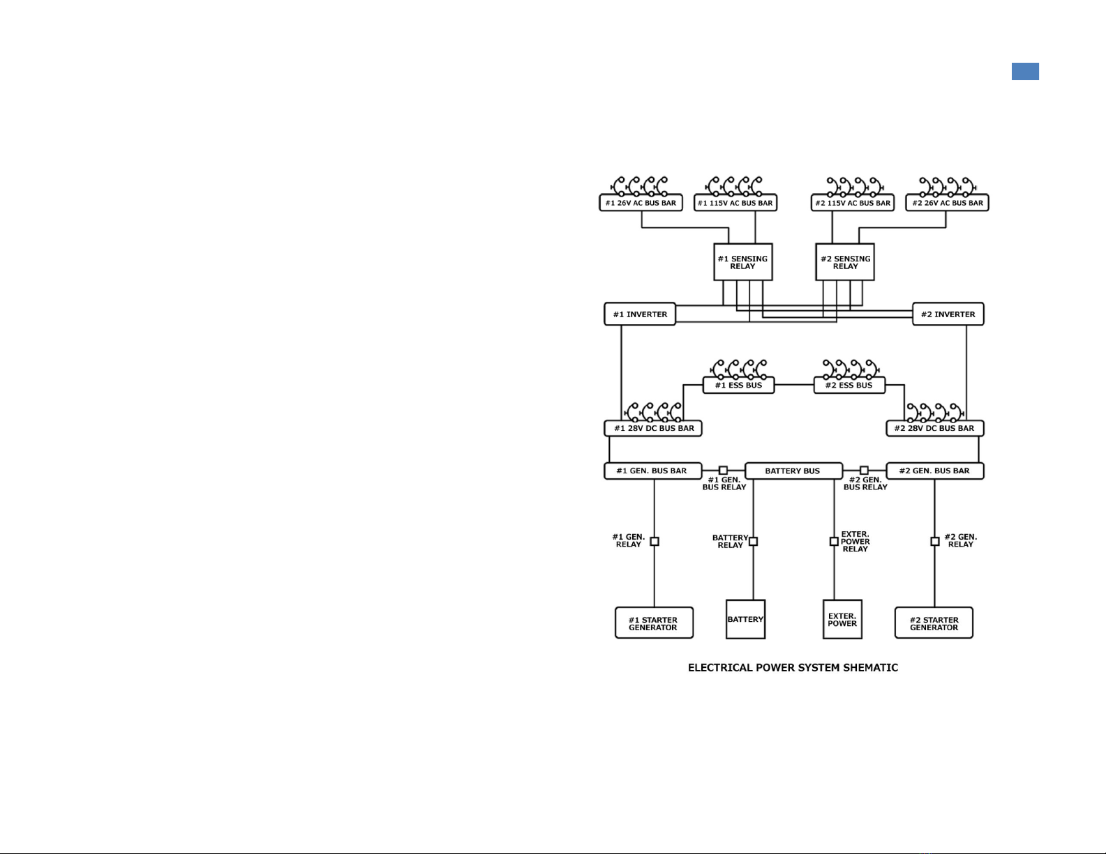
Two generators, a battery and, for ground handling, an external
power receptacle, are the dc power main sources. Two static
inverters, powered by dc voltage, are the ac sources. Both dc and
ac powers are distributed through a bus bar system and operated by
control switches located on the overhead console. The electrical
system is interfaced with the IDS for voltage, current, advisory,
caution and warning indications.
DC System
The dc electrical system is a 28 V direct current single conductor
system, using the helicopter structure as a negative ground. The
main components of the systems are two starter generators, two dc
control boxes, battery, external power receptacle and one dc relay
box.
The helicopter is equipped with a 2 V, 27 or 22 Ah or with a 25.2
V, 28 Ah nickel-cadmium battery located in the nose compartment.
A temperature switch, inside of the battery and connected to the
IDS, detects the internal temperature of the battery, giving a BATT
HOT warning message on the EDU 1 in case of battery
overtemperature.
The helicopter is provided with an external power receptacle on the
rear right side of the fuselage. A microswitch, activated by the
receptacle door, gives the EXT PWR ON advisory message on the
EDU 1 when the door is in the open condition.
Two starter-generators, installed each on the proper engine
reduction gear-box, provide engine start when operated as an
electric starter motor; after the engine start, the started generator,
driven by the engine, reverts into a dc generator providing the
necessary 28 V dc power.

9
Nemeth Designs/MILVIZ AgustaWestland AW109 for F X Operations Manual
AC system
The alternate power is supplied by two 250 VA single phase static inverters via two sensor relays. The inverters require 28 V dc power input
suppied by the dc main bus no.1, through the INV 1 circuit breaker and INV 1 ON/OFF switch, and the dc main bus no.2, through the INV 2
circuit braker and INV 2 ON/OFF switch.
The circuit breakers and control switches are located on the overhead console. Each inverter supplies 115 V ac and 26 V ac to its own 115 V
ac and 26 V ac distribution busses to which the helicopter ac loads are connected. In the event of an inverter failure, the relative sensing relay
deenergizes, connecting the failed inverter busses to the other operating inverter.

10
Nemeth Designs/MILVIZ AgustaWestland AW109 for F X Operations Manual
III. PANELS
Overview

11
Nemeth Designs/MILVIZ AgustaWestland AW109 for F X Operations Manual
1. MAIN PANEL
Medevac
1. Transponder radio
a) ON/OFF knob
b) Frequency adjust knobs
c) Frequency swap
2. NAV 2 radio
a) ON/OFF knob
b) Frequency adjust knobs
c) Frequency swap
2. NAV 2 radio
a) ON/OFF knob
b) Frequency adjust knob
c) Frequency swap
3. COM 2 radio
a) ON/OFF knob
b) Frequency adjust knobs
c) Frequency swap
4. GPS
a) COM frequency select for
adjust
b) NAV frequency select for
adjust
c) COM frequency swap
button
d) NAV frequency swap
buttone) Frequency adjust
knobs (mouse wheel) and
COM/NAV select (left
click)
f) NRST button

12
Nemeth Designs/MILVIZ AgustaWestland AW109 for F X Operations Manual
g) OBS button
h) MSG button
i) FLP button
j) TERR button
k) PROC button
l) RNG button
m) DTO button
n) MENU button
o) CLR button
p) ENTER button
r) Group/page adjust knobs
(mouse wheel) and
CURSOR (left click)
s) ON/OFF
5. COM 1 radio
a) ON/OFF knob
b) Frequency adjust knob
c) Frequency swap
6. NAV 1 radio
a) ON/OFF knob
b) Frequency adjust knob
c) Frequency swap
7. ADF radio
a) ON/OFF knob
b) Frequency adjust knob
c) Frequency swap
8. MASTER CAUTION
Annunciator
9. MASTER WARNING
Annunciator
10. Airspeed
a) IAS bug set
b) IAS gauge test
11. Attitude
a) Attitude cage button
12. Altimeter
a) Altimeter reference
pressure adjust knob
13. Verical speed
a) VS bug set
14. Audio panel
15. HSI 2
a) Show MAP in ARC mode
b) NAV bearing needle
source select
c) Course adjust knob
d) HSI/CDI needle source
select
e) ARC/HSI mode
f)-g) Zoom in/out
h) ADF bearing needle
source select
i) Heading bug adjust
16. EDU 1 display
a) ON/OFF button
b) Message scroll button
c) MENU
d) AUX mode
e) MAIN mode
f) TEST
17. EDU 2 display
a) ON/OFF button
b) Message scroll
c) MENU
d) START mode
e) CRUISE mode
f) OEI mode
g) TEST
18 HSI 1
a) Show MAP in ARC mode
b) NAV bearing needle
source select
c) Course adjust knob
d) HSI/CDI needle source
select
e) ARC/HSI mode
f)-g) Zoom in/out
h) ADF bearing needle
source select
i) Heading bug adjust
19. Chronometer
a) Stopwatch reset button
b) Mode select button
c) Start/stop button
20. DME
a) Source select/OFF knob
21. Backup attitude
22. Autopilot

13
Nemeth Designs/MILVIZ AgustaWestland AW109 for F X Operations Manual
VIP Transport
1. GPS
a) COM frequency select for
adjust
b) NAV frequency select for
adjust
c) COM frequency swap
button
d) NAV frequency swap
button
e) Frequency adjust knobs
(mouse wheel) and
COM/NAV select (left
click)
f) NRST button
g) OBS button
h) MSG button
i) FLP button
j) TERR button
k) PROC button
l) RNG button
m) DTO button
n) MENU button
o) CLR button
p) ENTER button
r) Group/page adjust knobs
(mouse wheel) and
CURSOR (left click)
s) ON/OFF
2. Audio panel
3. GARMIN GTX330
a) VFR (1200 preset)
b) ON
c) OFF
d) Numeric keys
e) Time mode select
f) Frequency set cursor
g) Start/stop for chrono
mode
h) Chrono reset

14
Nemeth Designs/MILVIZ AgustaWestland AW109 for F X Operations Manual
4. ADF radio
a) ADF 1/2 frequency select
b) ETE / flight time select
c) Flight time reset
d) ON/OFF knob
e) Frequency adjust knobs
5. GPS
a) COM frequency select for
adjust
b) NAV frequency select for
adjust
c) COM frequency swap
button
d) NAV frequency swap
button
e) Frequency adjust knobs
(mouse wheel) and
COM/NAV select (left
click)
f) NRST button
g) OBS button
h) MSG button
i) FLP button
j) TERR button
k) PROC button
l) RNG button
m) DTO button
n) MENU button
o) CLR button
p) ENTER button
r) Group/page adjust knobs
(mouse wheel) and
CURSOR (left click)
s) ON/OFF
6. MASTER CAUTION
Annunciator
7. MASTER WARNING
Annunciator
8. Airspeed
a) IAS bug set
b) IAS gauge test
9. Attitude indicator
10. HSI 2
a) Show MAP in ARC mode
b) NAV bearing needle
source select
c) Course adjust knob
d) HSI/CDI needle source
select
e) ARC/HSI mode
f)-g) Zoom in/out
h) ADF bearing needle
source select
i) Heading bug adjust
11. Altimeter
a) Altimeter reference
pressure adjust knob
12. Vertical speed
13. Backup attitude
14. DME
a) Source select knob
15. EDU 1 display
a) ON/OFF button
b)Message scroll button
c) MENU
d) AUX mode
e) MAIN mode
f) TEST
16. EDU 2 display
a) ON/OFF button
b) Message scroll
c) MENU
d) START mode
e) CRUISE mode
f) OEI mode
g) TEST
17. HSI 1
a) Show MAP in ARC mode
b) NAV bearing needle
source select
c) Course adjust knob
d) HSI/CDI needle source
select
e) ARC/HSI mode
f)-g) Zoom in/out
h) ADF bearing needle
source select
i) Heading bug adjust
18. Altimeter
a) Altimeter reference
pressure adjust knob
19. Vertical speed
a) VS bug set
20. Chronometer
a) Stopwatch reset button
b) Mode select button
c) Start/stop button
21. Autopilot

15
Nemeth Designs/MILVIZ AgustaWestland AW109 for F X Operations Manual
AUTOPILOT INSTRUCTIONS
The Autopilot (AP) of the Nemeth Designs/Milviz AW109 is
capable of holding altitude, heading, indicated airspeed, vertical
speed, VOR course, ILS course and track the GPS flight plan. The
AP can be activated with the standby (SBY) button. When the AP is
activated the different hold modes can be engaged by their
corresponding buttons. ALT mode holds the altitude on which the
ALT button is pressed. IAS model holds the indicated airpeed that is
set with the marker bug of the pilot’s IAS indicator. VS mode holds
the vertical speed that is set with the marker bug of the pilot’s VS
indicator.HDG mode holds the heading that is set with the heading
bug of the HSI(mouse wheel). NAV mode holds the HSI course of
the VOR that is set on the NAV1 radio. ILS mode holds the localizer
and glideslope of the ILS course that is set on the NAV1 radio. GPS
mode holds the track that is active on the GPS.
VS mode overrides the ALT mode. NAV mode overrides the HDG
mode. ILS mode overrides the ALT, VS, HDG, and GPS modes
however if there is no ILS glideslope the VS mode remains active.
The GPS mode overrides the HDG and NAV modes.
.
1.
Altitude hold
2.
Indicated airspeed hold
3.
Vertical speed hold
.
Heading hold
5.
Nav course hold
6.
Instrumental landing system hold
7.
GPS track hold
8.
Standby (AP engage/disengage)
Note: To work properly the AP requires the autorudder unction to be disabled in FSX realism settings. Also note, engaging 2 or more buttons
that do a similar unction will cause the AP to unction incorrectly, such as using the HDG and NAV buttons at the same time.

16
Nemeth Designs/MILVIZ AgustaWestland AW109 for F X Operations Manual
2. CENTER CONSOLE
1. Master avionics switch
2. Engine No.1 fuel cutoff switch
3. Fuel crossfeed switch
4. Engine No.2 fuel cutoff switch
5. No.1 main fuel pump switch
6. No.2 main fuel pump switch
7. Engine No.1 mode switch
8. Engine training mode switch
9. Engine No.2 mode switch
Note: HELIPILOT is not unctional in this release.

17
Nemeth Designs/MILVIZ AgustaWestland AW109 for F X Operations Manual
3. OVERHEAD PANEL
1. Pitot heat no.1 switch
2. Pitot heat no.2 switch
3. Copilot wiper switch
4. Pilot wiper switch
5. Inverter no.1 switch
6. Inverter no.2 switch
7. Interior light knobs
8. Position light switch
9. Anti-collision light switch
10. Generator no.1 bus switch
11. Generator no.2 bus switch
12. Passengers warining light switch
13. Engine no.1 fire extinguish button/fire warning annunciator
14. Fire extinguisher bottle no1./no.2 select
15. Engine no.2 fire extinguish button / fire warning annunciator
16. Load/share select switch (keep matched engine torque or TOT)
17. Engine no.1 de-ice switch
18. Engine no.2 de-ice switch
19. Battery switch
20. Generator no.1 switch
21. Generator no.2 switch
22. Cabin light switch
23. Rotor brake lever
24. Engine no.1 control lever (manual gov. mode)
25. Engine no.1 starter button (manual gov. mode)
26. Engine no.2 starter button (manual gov. mode)
27. Engine no.2 control lever (manual gov. mode)
28. Cabin ventilation system switch
29. Cockpit ventilation system switch
30. Environmental control system (ECS) master switch
31. ECS mode select switch
32. ECS temperature adjust knob

18
Nemeth Designs/MILVIZ AgustaWestland AW109 for F X
Operations Manual
4. MIDDLE PANEL
1. Landing gear control lever
2. Landing gear control mode select switch
3. Parking brake handle
4. Landing gear annunciators
5. Hydraulic/servo switch
6. Air source select lever (outside/ECS). When the ECS is active
and the temperature is set correcly on the ECS section of the
overhead panel this lever removes the moisture from the
windows when it’s in ECS (HEAT/COND) position.
7. Nose wheel lock

19
Nemeth Designs/MILVIZ AgustaWestland AW109 for F X Operations Manual
5. COLLECTIVE LEVER
1. Engine no.1 governing mode select switch
2. Engine no.2 governing mode select switch
3. NR/N2 speed to 102%
. Search light control knob
5. Search lights ON/OFF switch
6. Landing light ON/OFF switch (OFF / nose only / nose and wing
beams)
7. Engine trim switches

20
Nemeth Designs/MILVIZ
AgustaWestland AW109 for F X
Operation
s
Manual
IV. CHECKLISTS
1. PRE-START CHECK
All switches: OFF or CLOSED.
Nose wheel lock: ON (lever up).
Parking brake: ON (pull out and turn).
Cyclic stick: Centered
Collective lever: Full down
Engine power levers: OFF (full aft).
ENG 1 and 2 MODE switches: OFF (fully counterclockwise).
LD-SH switch: As required.
NOTE
The LD - SH switch allows the pilot to keep matched engine
torque or TOT, as required.
OEI TNG switch (if installed): Off position (centered), check.
Altimeter: Set.
STATIC source switch: NORM and protected.
LDG GEAR control lever: DOWN, check.
SERVO (Main hydraulic): NORM.
External power (if used): Connect.
NOTE
Be sure that the external power source supplies not less than 8
volts. The battery is automatically disconnected when an external power source is connected to the helicopter.
Check that BATT OFF caution message is displayed on EDU 1 if the external power is used.
Battery: ON.
GEN BUS 1 and 2: ON.
GEN 1 and 2: ON
Electronic Display Units (EDU 1 and EDU 2): Check on.
NOTE
Both EDUs are automatically activated when the helicopter is
electrically powered: EDU 1 in CRUISE mode and EDU in
Fuel quantity: Check.
RPM switch (on collective control): Set 100%.
Table of contents
Popular Toy manuals by other brands

Hasbro
Hasbro NERF Power Moves Marvel Avengers Thor Hammer... quick start guide

Heli-Max
Heli-Max Axe CX Micro PRE-FLIGHT CHECKS AND REPAIR

Eduard
Eduard 32 545 instruction sheet

Pilot Communications
Pilot Communications Viper Jet 73" user manual

WOODLAND SCENICS
WOODLAND SCENICS SCENIC RIDGE ST1482 Instruction booklet

Nine Eagles
Nine Eagles SOLO PRO instruction manual