51.800.627.4499
Subject to change without notice: RENEWAIRE.COM | 1.800.627.4499 54 Subject to change without notice: RENEWAIRE.COM | 1.800.627.4499
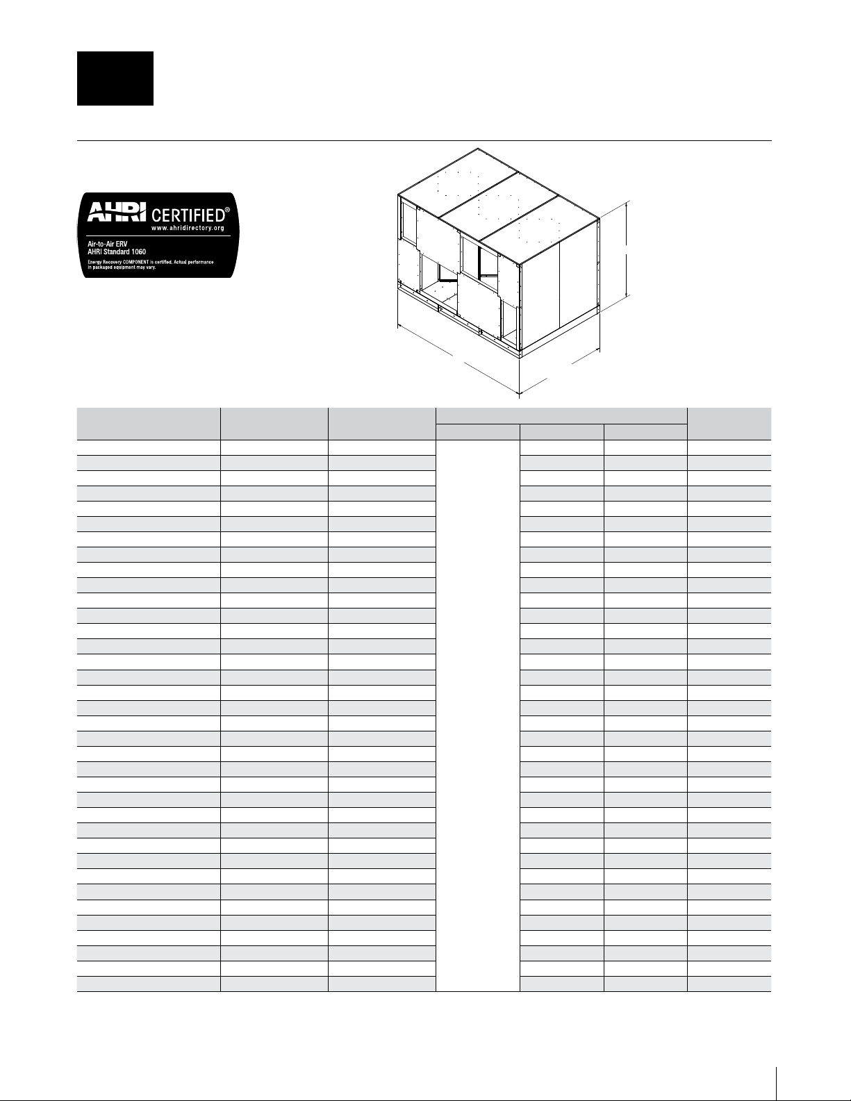
SPECIFICATIONS & DIMENSIONS
Unit
(Cores High and Wide)
Typical Airflow Range
(CFM)
AHRI 1060 Certified
Cores (L125-G5)
Unit Dimensions Weight
(lbs.)
L (Inches) W (Inches) H (Inches)
SA3H3W 2,250–9,900 9
64 1/2
97 3/4 65 5/8 1,300
SA3H4W 3,000–13,200 12 130 1/4 65 5/8 1,675
SA3H5W 3,750–16,500 15 162 7/8 65 5/8 2,049
SA3H6W 4,500–19,800 18 195 3/8 65 5/8 2,424
SA3H7W 5,250–23,100 21 228 65 5/8 2,798
SA3H8W 6,000–26,400 24 260 1/2 65 5/8 3,172
SA4H3W 3,000–13,200 12 97 3/4 85 1/2 1,582
SA4H4W 4,000–17,600 16 130 1/4 85 1/2 2,030
SA4H5W 5,000–22,000 20 162 7/8 85 1/2 2,479
SA4H6W 6,000–26,400 24 195 3/8 85 1/2 2,927
SA4H7W 7,000–30,800 28 228 85 1/2 3,376
SA4H8W 8,000–35,200 32 260 1/2 85 1/2 3,825
SA5H3W 3,750–16,500 15 97 3/4 105 3/8 1,863
SA5H4W 5,000–22,000 20 130 1/4 105 3/8 2,384
SA5H5W 6,250–27,500 25 162 7/8 105 3/8 2,908
SA5H6W 7,500–33,000 30 195 3/8 105 3/8 3,431
SA5H7W 8,750–38,500 35 228 105 3/8 3,954
SA5H8W 10,000–44,400 40 260 1/2 105 3/8 4,477
SA6H3W 4,500–19,800 18 97 3/4 125 1/2 2,203
SA6H4W 6,000–26,400 24 130 1/4 125 1/2 2,819
SA6H5W 7,500–33,000 30 162 7/8 125 1/2 3,435
SA6H6W 9,000–39,600 36 195 3/8 125 1/2 4,051
SA6H7W 10,500–46,200 42 228 125 1/2 4,666
SA6H8W 12,000–52,800 48 260 1/2 125 1/2 5,282
SA7H3W 5,250–23,100 21 97 3/4 145 3/8 2,483
SA7H4W 7,000–30,800 28 130 1/4 145 3/8 3,174
SA7H5W 8,750–38,500 35 162 7/8 145 3/8 3,864
SA7H6W 10,500–46,200 42 195 3/8 145 3/8 4,554
SA7H7W 12,250–53,900 49 228 145 3/8 5,244
SA7H8W 14,000–61,600 56 260 1/2 145 3/8 5,934
SA8H3W 6,000–26,400 24 97 3/4 165 1/4 2,765
SA8H4W 8,000–35,200 32 130 1/4 165 1/4 3,529
SA8H5W 10,000–44,000 40 162 7/8 165 1/4 4,294
SA8H6W 12,000–52,800 48 195 3/8 165 1/4 5,058
SA8H7W 14,000–61,600 56 228 165 1/4 5,822
SA8H8W 16,000–70,400 64 260 1/2 165 1/4 6,587
Performance:
Model: SA3H3W CATALOG
Drawing Type: Unit Dimension
Cross flow arrangements have best thermal
performance compared to parallel flow arrangements.
See IOM for complete thermal performance.
Version: FEB20
1 = OA: Outside Air intake
2 = SA: Supply Air to inside
3 = RA: Room Air to be exhausted
4 = EA: Exhaust Air to outside
INSTALLATION ORIENTATION
Unit must be installed in orientation
shown.
NOTE:
1. UNLESS OTHERWISE SPECIFIED,
DIMENSIONS ARE ROUNDED TO THE
NEAREST EIGHTH OF AN INCH.
2. SPECIFICATIONS MAY BE SUBJECT
TO CHANGE WITHOUT NOTICE.
3. FILTERS REQUIRED ON UPSTREAM
SIDE OF CORES.
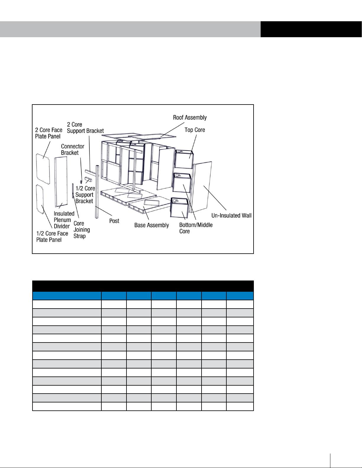
4. UNIT WILL SHIP DISASSEMBLED AND
REQUIRES ON-SITE ASSEMBLY.
5. DUCT WORK SUPPLIED BY OTHERS.
6. AIR STREAMS 1-2 CAN BE
INTERCHANGED WITH AIRSTREAMS 3-
4. EACH AIRSTREAM IS REVERSIBLE.
W
L
64 1/2"
H
SA SERIES DIMENSIONS
SERIESSA Energy Recovery Core Array
Energy Recovery Core is AHRI Certified®