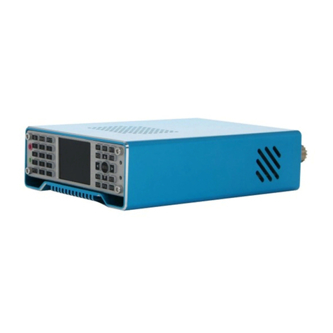
Ailunce HS1 User manual

Ailunce HS1 User’s Manual
1
Ailunce HS1 USER’S MANUAL

Ailunce HS1 User’s Manual
2
Preface:
This manual is for the HS1 transceiver, a good color tft display
screen for it and good trx. As an open-source SDR (Software
Defined Radio), both in terms of Software and Hardware. As such,
the features of this transceiver will continue to evolve and this
manual is intended to provide a reference source.
Main Features
• Spectrum Dynamic Waterfall Display
• Multiple Working Modes:Receive Mode, Transmit Mode,
TUNE Mode, VFO Mode, SPLIT Mode
• DSP Digital Signal Processing Noise Reduction
• Automatic Notch Filter
• Receive Fine Tuning Function, Changeable MIC Gain Value
• VCC Power Supply Voltage Indication Table
• Transmit Signal Strength Display Table
• Multifunctional Instrument:SWR Standing Wave Ratio Meter,
AVD Audio Frequency Meter, ALC Signal Modulation Meter
Parameter:
Frequency Range
RX:0.5MHz-30MHz
TX:0.5MHz-30MHz
Output Power
Maximum 15W
Receiving Sensitivity
Better than -115dBm
Operating Mode
Full Modes
Operating Voltage Range
DC 9-15V
Dimensions
190mm*69mm*45mm
Maximum Current
3.5A
Transceiver comes with automatic key generator circuit, Can
be connected to the use of automatic keys.

Ailunce HS1 User’s Manual
3
Front Panel controls:
All of the controls are defined in software, but for the purpose of
simplicity they are typically defined as follows:
Figure 1:Front panel controls of the HS1 transceiver
Power ~ This turns the transceiver on, but it is also used to turn
the transceiver off and save configuration and frequency
mode/memories. A brief press of this button will also select the
brightness of the LCD backlight. Please read notes about the
backlight and the possibility of its injection of a tone into the
receiver when a “dim”mode is selected. Low brightness will
cause the noise inside the machine to increase, and there is no
such noise at 100% brightness.
Important:
If you have not already done so, please find the menu
item “RX/TX Freq Xlate” and set it to “RX Low LOW”
as this will improve receive and transmit performance.
See this item's menu description in this manual for more
details.
Band-, Band+ ~ These buttons select the next lower or higher
amateur band. When the lowest or highest band is reached it
“wraps around” to the highest/lowest band. Pressing and holding
the Band- along with the Power button may be used to turn
on/off the automatic backlight blanking feature while pressing
and holding the Band- and Band+ buttons will toggle between
the display of the Spectrum Scope and Waterfall Display
STEP-, STEP+ – This sets the tuning step size in steps that
include 1 Hz, 10 Hz, 100 Hz, 1 kHz, 10 kHz, and 100 kHz. The
function of these buttons may be swapped via a menu setting.
Pressing and holding of one of these buttons will temporarily
change the step size to facilitate tuning in smaller or larger steps
while pressing-and-holding both of these buttons simultaneously
will toggle “frequency lock” on and off, with “on” being
indicated by the main Frequency readout being displayed in
grey.
FREQ ENC – This is used to tune the transceiver's operating
frequency, the tuning steps being set by the STEP- and STEP+
buttons.
ENC1,AF – Rotary encoder ENC1is typically used to adjust the
volume, but its function may be changed using button AF to
adjust the side tone gain
ENC2, RF – Rotary encoder ENC2 is typically used to adjust
the RF gain (or squelch in FM mode but its function may be
changed using button RF to adjust the action of the DSP Noise
Reduction or Noise Blanker strength. In the Menu mode it is

Ailunce HS1 User’s Manual
4
used to select the item to be adjusted. Pressing-and-holding
button RF when in normal (non-menu) receive mode will
switch between the right-hand function adjusting the DSP Noise
Reduction or the Noise Blanker “strength.”
ENC3, RIT – Rotary encoder ENC3 is typically used as an
RIT (Receiver Incremental Tuning) but its function may be
changed using button RIT to adjust the sending speed (in Words
Per Minute) in the CW mode, or to adjust the Microphone or
Line-In gain in voice mode. In the Menu mode it is used to
modify the item selected, or button RIT may be
pressed-and-held to select whether Microphone-In or Line-Input
mode is active and to be adjusted.
Mode – This button is used to select the operating mode of the
transceiver (CW, USB, LSB, etc.) Pressing this button cycles
through the available modes.Pressing-and-holding this button
will allow the selection of a mode that is disabled in the menu
system (e.g. AM.)
When “LSB/USB Auto Select” is enabled, pressing button
Mode will skip the sideband that is not appropriate for the
frequency of operation (e.g. USB will not be selected below 10
MHz) but pressing-and-holding this button when LSB is
displayed will change the mode to USB – and
Pressing-and-holding again will change it back to LSB. When
menu item “LSB/USB Auto Select” is enabled, in order to
change to AM you must select a mode other than LSB (or USB)
– such as CW – and then press-and-hold button Mode - AM will
then be selected.
DSP – This button is used to control the DSP audio filter mode.
Pressing-and-holding will turn DSP on/off while preserving the
current settings. Pushing this button will also “reset” the DSP.
PA – This button is used to set the transmit power level (FULL,
5 Watts, 2 Watts, 1 Watt, 0.5 watts, and back to FULL.)
Note: The power is automatically limited to 2 watts in
AM Transmit mode. When in CW, LSB or USB mode
(those modes with a “BFO”) pressing-and-holding this
button will cause a tone with a frequency equal to that
of the CW sidetone and transmit shift to be sounded.
Figure 2: Main display of the HS1 transceiver

Ailunce HS1 User’s Manual
5
BW – This button is used to select the audio pass band filter of
the receiver. Pressing-and-holding this button will force the
selection of bandwidth that are otherwise disabled. The
filter-selection function of this button is disabled when the FM
mode is selected, but pressing-and-holding it while transmitting
on FM will cause a tone burst to be generated, if this feature is
enabled.
Buttons F1-F5 are “soft” buttons located under the display, the
functions of which change depending on mode, indicated on the
LCD itself and will be discussed in more detail later in this
document.
Also on the front panel are two LEDs, LD1 on the left and LD2
on the right. LD1, which is typically green, is illuminated on
receive and LD2 which is typically red is illuminated on transmit.
Main Display:
Figure 3: The main screen (annotated) with the SPLIT function activated.
When “Frequency Translate” mode is on, the center frequency indicator
will be shifted to the left or right of center by 6 kHz.
On the main display, just above the Spectrum Scope, there are a
number of indicators:
• Main Frequency Display: This may be displayed
either as a single frequency (transmit/receive as in
Figure 2) or as a “Split” display as shown in Figure 3
with separate transmit and receive frequencies. If the
numbers in this display are grey the “Frequency
Lock”(toggled by pressing-and-holding both the STEP-
and STEP+ buttons simultaneously, or configured in
the menu)is active. If this display is yellow, a
transverter offset has been configured.

Ailunce HS1 User’s Manual
6
• RIT+Tuning Display: Above and to the right of the
main frequency display is a smaller display that is offset
from the main display if the RIT is set to something other
than zero.
• Band Display: To the right of the main display is an
indicator of the amateur band in which the current
frequency is tuned. If the current frequency is outside an
amateur band it will display “Gen” (e.g. “General
Coverage”).
• Mode Indicator: Above the “10's” digit of the main
frequency display is the current mode displayed on a blue
background.
• Step Size Indicator: Above the center of the main
frequency display, between the Mode Indicator and the
“Sub” Frequency display is the setting of the current step
size. In Figures 2 and 3 the step size is set to 1 kHz.
Optionally, a “marker” may be activated that puts a line
under the digit indicating the currently-selected step size
(see the menu item “Step Size Marker”).
Along the top there are a number of additional indicators:
• TCXO Mode/Display: In the top-left corner the
“TCXO” box indicates whether the TCXO
(Temperature-Compensated Xtal Oscillator) is active or
not. The TCXO is used to read the temperature of the
Si570 synthesizer (U8 on the RF board) - which should be
thermally-bonded to the temperature sensor, U10, with a
piece of copper or aluminium - and apply a
compensation to it to keep on frequency. When it is active
the bar graph below the temperature display will display
white dots with a blue marker that moves about but when
set to “Off”, the bar graph will be grayed out. If set to
“Stop” the temperature display will be replaced with
“STOPPED”. In Figures 2 and 3 the TCXO is set to ON
and displaying a temperature of 112.5F, but this may be set
to display the temperature in Centigrade. If the temperature
is very low(below 0C or 32F)this will display dashes and
the temperature compensation will be disabled until the
temperature-coupled synthesizer/sensor exceed this
minimum threshold.
• S-Meter: This S-meter is nominally calibrated so that S-9
equals 50 micro volts into a 50 ohm load with each S-unit
representing 6 dB. Practically speaking, the usable range of
the S-meter ranges from about S-3 to something a bit
higher than “40 over” which, if you were “run the
numbers” about matches the dynamic range of the
receiver! The bottom half of the S-Meter's graticule
(“S0-S9”) is normally white in color, but if the receiver's
A/D converter experiences an overload condition, it will
turn red. On bands with strong signals it is normal for this
to momentarily flash red as the internal gain control adjusts
itself. In Figures 2 and 3 the S-meter is displaying a signal
level of S-9.
•PO: The S-Meter scale, when in transmit mode, also

Ailunce HS1 User’s Manual
7
indicates the output power from the transmitter.
• Multi-function display: Below the S-Meter and Power
Output meter is a multi-function meter that, using button
F2, may be used to select one of three modes:
SWR,AUDIO, and ALC.
• SWR: When in transmit mode, this meter indicates the
calculated VSWR.Note that the VSWR is calculated only
when the forward power exceeds 0.25 watts. When in
SSB mode, this indicator will not show any VSWR
indication unless/until there has been some RF power that
exceeds the minimum power, allowing a calculation to be
made.
• AUD io: This indicates, in dB, the relative audio level
being applied to the MIC/Line input.
• ALC: This indicates, in dB, the amount of gain reduction
that the ALC is applying while in transmit mode. 3-12dB of
indication during typical speech is normal.
Along the left-hand edge there are a few more indicators,
starting from the bottom-left corner:
• VCC: Below this is a voltmeter that indicates the current
supply voltage.Below 9.50 volts, the digits are displayed in
red, orange below 10.5 volts and yellow below 11.0 volts.
The receiver may function as low as 8 volts, but obtaining
more than 3-5 watts of “clean” transmitter power may not
be possible below 10.5 volts, particularly on the higher
bands.
• FIL: Below this is the current filter bandwidth setting,
selectable by using button BW. In Figures 2 and 3the
bandwidth is shown being set to 2.3 kHz.
• Power Output Setting: Just above the FIL icon is the
currently-selected output power setting, selectable using
buttonG3. In Figures 2 and 3the power is shown being set
to 5 watts.
• DSP Setting: Just above the Power Output Setting is the
indicator of the DSP mode. The modes available are:
“OFF”,“NR”(Noise Reduction), “NOTCH”, and
“NR+NOT”(Noise Reduction and Notch).
Spectrum display:
Below the frequency readout, shown in Figure 2andFigure 3is a
spectrum display that shows signals that are on either side of the
current tuned frequency. Along the bottom of the spectrum display
is a frequency scale that shows the frequency scaling of the
graticules rounded to the nearest kHz. This display works very
much like a spectrum analyzer with the vertical scale being
represented logarithmically, the number of dB/division being
selectable by the user. To further the analogy to a spectrum
analyzer, the“reference level”(the signal level at which a particular
strength is indicated) is automatically adjusted via an AGC
(Automatic Gain Control) within the spectrum scope that operates
independently from the receiver's AGC that automatically scales
the strongest signal within the passband such that it is at/near the
top of the scope–this, to allow the representation of widely varying
signals on different bands without the need of user adjustment.

Ailunce HS1 User’s Manual
8
Waterfall display:
Figure 4 shows an alternate method of displaying signals near the
currently-tuned receiver signal is the Waterfall Display. In this
mode, the frequency is displayed along the “X” (horizontal)
axis,just as in the case of the Spectrum Scope but instead of the
signal strength being displayed as height, it is displayed as relative
“brightness”. The waterfall displayed is so-called because it can
convey the history of recent signal in time by showing the most
recent signals at the bottom,but when new signals are analyzed,
the older signals are displaced vertically and the newest signals
are placed along the bottom. In this way, one has a quick visual
“history” of what has occurred not only on the center frequency.
Figure 4: A typical waterfall display in the "Magnify" mode
showing +/- 12 kHz (24 kHz) of a band segment. When "magnify"
mode is NOT active +/-24 kHz (48 kHz) of a band is visible.
Options available to both the Spectrum Scope and Waterfall
Display:
•An adjustable “smoothing” filter (menu item “Scope/Wfall
Filter”) is available that dramatically improves the visibility of
rapidly-changing signals In the menu system, the range of the
Spectrum Scope may be set to span either +/- 24 kHz or +/- 12
kHz, with the scope's AGC operating only on signals within the
displayed span – see the menu setting “Spec. 2x magnify” for
more information.
• Also available are “Window function” selections that operate on
the input FFT data to both the Spectrum Scope and the Waterfall
Display that pre-process the spectral data to minimize “spill-over”
of adjacent FFT “bins”. What this can do is make the Spectrum
Scope and Waterfall display look “sharper” and prevent a strong
signal from “leaking” over and covering a weak one.
Connectors:
On the right-hand side of the transceiver on the UI board are four
3.5mm three-conductor connectors. Starting from the top, these
connectors are:
• Line Out (J1). This is a receive audio output that is fixed
level (unaffected by the volume control) that may be used to
supply audio to a computer for “sound card” (digital) modes.
This connector also carries the audio being transmitted.
• Line In (J2). This input may come from a computer for
“sound card” (digital) for transmitting. Its use must be
selected in the menu for it to be used.

Ailunce HS1 User’s Manual
9
• Microphone/PTT (J3). This connector has both a
microphone connector with bias voltage (if R68 is installed)
for powering an electret microphone and a PTT
(Push-to-Talk) line that is shorted to ground to key the radio.
While the PTT line is always active, the microphone must
be selected as the active audio input from the menu for it to
be used. (Note that this is also the “Dah” line, which is also
used for keying in CW “straight key” mode.)
• Speaker/Phones (J4). This jack feeds and external
speaker/headphones, disconnecting the internal speaker when
something is plugged into it.
• Warning: There is no limiting resistor in series with
this audio connection, so you must remember to turn
down the volume before plugging in headphones.
On the RF board, along the right side, there are three connectors.
Starting from the top these connectors are:
• Power connector (J1). This is a coaxial power connector,
5.5mm O.D., 2.1mm I.D., that supplies power to the
transceiver. The outer shell is negative and the inner
conductor is positive.
• Paddle (J2). This connects to either a set of Morse paddles
or a straight key. The outer conductor (“ring”) is typically the
“Dah” while the tip is the “Dit” when in Iambic mode. In
“Straight Key” mode only the outer conductor (“ring”) is
used. (The “Dah” line is the same as the “PTT” line.)
• Accessory (J3). This is used for interfacing with an
external device and may be used for keying the transmitter
and/or determining when the transmitter is keyed. The “tip”
of this jack is the “PTT”/”Dah” line and may be used when
interfacing the transceiver to a computer when operating a
digital mode. The outer conductor (“ring”) is grounded
when the transceiver is in transmit mode and this may be
used to key an external amplifier or TR switch.
• The upper, “A” type (full-sized) USB connector is a USB
host port that may have future use for storage of data/audio
files and/or interface devices such as keyboards and wireless
devices. It is also possible to load firmware from a USB
memory stick from the interface.
• The lower “mini” USB host port is primarily used for
programming firmware into the transceiver.
On the left-hand side of the UI board are two USB connectors.
Finally, the sole connector on the left-hand side of the RF board is
the BNC-type antenna connector, the nominal impedance being 50
ohms.

Ailunce HS1 User’s Manual
10
Operational modes and functions:
After powering up, the HS1 transceiver will revert to receive
mode on the last frequency, in the mode and using the audio
bandpass filter that was in use when it was last powered down
using the POWER button. In this mode LD1, the left-hand LED
(typically green) is illuminated.
By default, ENC1 controls the volume, ENC2 the RF Gain and
ENC3 controls the RIT.
When in transmit mode LD2 (typically red) the right-hand LED is
illuminated. In transmit mode most of the controls are frozen, this
being done to prevent the change of frequency, filter type and
mode during mid-transmission.
Tune mode may be entered by pressing the button located below
the TUNE icon on the screen (e.g.button F5) at any time and in
this mode a carrier is generated, along with an audible sidetone in
the speaker, the amplitude being set by the “Sidetone Gain” (STG)
setting. The output power may adjusted during transmit by
pressing the button PA to cycle through the settings. The TUNE
label on the LCD will turn red while TUNE mode is active.
Pressing the TUNE button again will exit.
Receive mode:
Transmit mode:
TUNE mode:
Always have a suitable load connected to the transmitter
(matched antenna or dummy load) before entering TUNE mode
or ANY transmit mode.
Notes:
When not in Menu mode, “soft” button F4, beneath the display. This button
toggles which VFO, A or B, is currently the “Active” VFO. This display
will change, always indicating the currently-active VFO.
If SPLIT mode is not active, the currently active VFO's frequency, filter
selection and mode are used for both receive and transmit.
If SPLIT mode is active the currently active VFO's frequency and filter are
used for receive while the “other” VFO's frequency is that used for
• When in TUNE mode audio being input to the Microphone and
LINE inputs will be ignored.
• When TUNE is activated in SSB mode, the frequency offset from
the display frequency and the sidetone frequency (e.g. the tone
emitted from the speaker) will always be 750 Hz.
• Note: There will be no tone in SSB-TUNE mode when frequency
translation is active.
• When TUNE is activated in CW mode the frequency offset from the
display frequency and the sidetone frequency will be that configured
as the sidetone frequency in the menu.
• Pressing-and-holding the TUNE button will toggle the Transmit
Disable function. If this is activated the TUNE indicator above button
F5 will be displayed in grey and pressing it will have no effect. The
“Transmit Disable” function may also be enabled/disabled in the
configuration menu.
VFO A (or VFO B):

Ailunce HS1 User’s Manual
11
transmit: The transmit mode is always that of the “active” (receive) VFO.
The SPLIT mode will be discussed in more detail below.
If one PRESSES AND HOLDS this button (F4) the currently active VFO's
mode, filter setting and frequency are copied to the inactive VFO with an
on-screen indication that this has taken place.
When not in Menu mode, “soft” button F3 toggles “SPLIT” mode
on and off.
When SPLIT mode is off the radio behaves normally, using the
currently selected VFO for both receive and transmit.
When SPLIT mode is on, the radio uses the currently-selected
VFO's mode for both receive and transmit, the current VFO's filter
and frequency for receive and the “other” VFO's frequency for
transmit. In this mode, the main frequency display is also changed,
showing both the receive and transmit frequency, separately.
To set up for SPLIT mode one might do the following:
• Activate the SPLIT function. “SPLIT” has now changed color and the
display shows two frequencies.
• Suppose that a DX station is transmitting on 14.155 and
receiving on 14.165, USB. In that case, you would transmit on 14.165
and receive on 14.155.
• Dial in your transmit frequency of 14.165 MHz – the receive
frequency of the DX station.
• Press the VFO A/B button to move that frequency to the “other”
VFO: That is now your transmit frequency.
• Dial in your receive frequency of 14.155 – the transmit frequency
of the DX station – and also set USB mode and your desired filter
bandwidth.
• You are now ready to go! - It doesn't matter which frequency is in
VFO A or B.
• When installing and then using this firmware for the first time
there may be a problem with saving the VFO A/B frequencies. After
using the POWER button to save the settings once or twice it
appears as though the memory locations get properly initialized and
that they work as they should thereafter.
• The SPLIT mode works only on the same band – this to prevent the
destructive battering of the band-switch relays that might occur with
crossband operation – which would also slow down transmit/receive
switching.
• When using FM mode it is possible to use the SPLIT function for
repeater operation if one VFO contains the repeater input frequency
and the other contains the repeater output frequency. By “swapping”
the VFOs one may also do a “reverse” function and listen to signals
on the repeater's input frequency.
Important Comments related to SPLIT mode and VFO A/B:
◎Note that it is possible for one to set the STEP to 100 kHz
and using the main knob to tune the receive frequency to
another band and operate split that way, but this is not
recommended and you do this at your own risk!
SPLIT:

Ailunce HS1 User’s Manual
12
In “normal” operation the spectrum display will be visible on the
screen and the five “Function” buttons along the bottom of the
display will have the following functions:
“Soft” buttons in normal operation:
•MENU (button F1) – This enters the menu system, allowing the
configuration of the transceiver. Pressing and holding this button will
save all settings to EEPROM.
•METER (button F2) – This button selects the mode of bar graph
below the S-meter which is used to display different parameters while
transmitting. Repeatedly pressing this button selects, in turn, the display
of SWR, AUD and ALC.
•SPLIT (button F3) – This button toggles “SPLIT” mode on/off. When
on (“SPLIT” is yellow), the transmit and receive frequencies are
separated using VFO A and B as shown on the main frequency display.
•VFO A or VFO B (button F4) – This button toggles whether VFO A
or VFO B is the “primary” VFO. The VFO that is being displayed is
ALWAYS the one being used for receive.
•TUNE (button F5) – This button toggles the TUNE mode on/off.
Pressing and holding this button will disable transmit as indicated by
this indicator being displayed in gray.
Pressing the MENU button (e.g. button F1) will enter the main menu system
by which many parameters of the transceiver may be configured: These
parameters will be discussed in detail later. Pressing-and-holding this button
will save all settings to EEPROM.
Upon entering the MENU mode several of the “soft” buttons along the
bottom of the screen willchange their function:
“Soft” buttons in MENU mode:
•EXIT (button F1) – This exits the menu system, returning to the
main display. Pressing-andholding this button will save all settings to
EEPROM.
•DEFLT (button F2) – This button resets the currently-selected item
to its default setting.
•PREV (button F3) – This button goes backwards one screen or six
menu items. Pressing-andholding this button will jump to the
beginning of the menu, or to the end of the menu if already at the
beginning.
•NEXT (button F4) – This button goes forwards one screen or six
menu items. Pressing-andholding this button will jump to the end of
the menu, or to the beginning of the menu if already at the end.
• The TUNE mode remains present while in the MENU system at
button F5
Note: If an item has been changed in the menu system that may
need to be saved to EEPROM using the POWER button, the
MENU indicator will be orange and be followed by an asterisk
(e.g. “MENU*”)
Configurable options on the main screen:
In the upper left corner there are a number of items on the main
screen that are configurable using the buttons and/or encoders
•AFG - “AF Gain” (a.k.a. “Volume Control”). This is used to adjust
the audio level feeding the speaker/headphone jack using encoder
ENC1. Button M1 may be used to select whether this encoder adjusts
AFG or STG (see below) with the “un-selected” item being “grayed”
out. AFG (e.g. the “Volume control) is always enabled when in Menu
mode.
•STG - “Sidetone Gain” while in CW mode. This is used to adjust the

Ailunce HS1 User’s Manual
13
level of the sidetone that is heard during keying while in CW mode
and while in TUNE mode using encoder ENC1. Button M1 may be
used to select whether this encoder adjusts STG or AFG with the
“unselected” item being “grayed” out. Sidetone Gain is also
adjustable from the main menu. When not in CW mode this is
replaced with “CMP”.
•CMP - “TX Compression Level” while not in CW mode. This is
used to adjust the amount of audio compression when in voice mode.
When in CW mode this is replaced with “STG”.
•RFG - “RF Gain”. This control, as the setting is decreased, causes
an increased deflection in the S-Meter and a commensurate decrease
in the receiver sensitivity. This functions in exactly the same way as
the “RF Gain” control on a traditional analog receiver and is typically
used to limit the receiver sensitivity on a noisy band. Button M2 may
be used to select whether this encoder adjusts RFG or NB (see below)
with the “un-selected” item being “grayed” out. This
parameter may also be adjusted from the main menu.
•DSP – This adjust the “strength” of the DSP noise reduction, when
enabled. Pressing-andholding button M2 will select between this
parameter or “NB”(Noise Blanker adjust) being visible. Turning the
DSP on and off will also reset the DSP noise reduction/notch engine.
•NB - “Noise Blanker”. This control adjusts the “strength” of the
noise blanker, with “0” being “disabled.” This is a “pulse” type noise
blanker operating on the wideband input prior to filtering in the DSP
input. As the noise blanker strength is increased, the color of the
number changes to warn the user that the higher numbers are more
likely to cause degradation of the receive audio. Button M2 may be
used to select whether this encoder adjusts NB or RFG with the
“un-selected” item being “grayed” out. Pressing-and-holding button
M2 will select between this parameter or “DSP” being visible.
•RIT - “Receive Incremental Tuning”. This offsets the receiver, in 20
Hz steps, to allow the transmit frequency to be different from that of
the receiver with the actual receive frequency being shown on the
“sub” frequency display above and to the right of the main frequency
display. Button M3 may be used to select whether this encoder adjusts
RIT or WPM (see below) with the “un-selected” item being “grayed”
out.
•WPM - “Words Per Minute” while in CW mode. This adjusts the
Morse sending rate in “Words Per Minute” when using Iambic mode
keying. Button M3 may be used to select whether this encoder adjusts
WPM or RIT (see below) with the “un-selected” item being
“grayed” out. The Morse WPM setting may is also adjustable from
the main menu. When not in CW mode this is replaced with “MIC”
or “LIN”.
•MIC or LIN - “Microphone Gain” or “Line Input Gain” when not
in CW mode. This adjusts the Microphone (or Line Input) gain,
depending on which is enabled. When in CW mode this is replaced
with “WPM”. Pressing-and-holding button M3 will select
Microphone or Line-Input modes. Note that if this is changed during
transmitting, one must briefly unkey for the change of inputs to take
effect.
Automatic switching of on-screen items when going from
receive to transmit:
Using the item in the “Configuration Menu” labeled “O/S Menu
SW on TX” and setting it to ON several of the on-screen items
will change automatically when going from receive to transmit and
back again when returning to receive when in SSB mode: This
function is NOT available in CW mode.

Ailunce HS1 User’s Manual
14
These parameters include:
▪ This automatic switching facilitates the adjustment of the relevant
parameters when in transmit mode without having to pause and press the
M1 and/or M3 buttons to switch the functions of the relevant knobs.
▪ Note that if you already had selected an alternate function while in receive
(e.g. “CMP”) it will “remember” and return to that setting after you have
been in transmit and again turned to receive.
▪ Setting the parameter “ O/S Menu SW on TX” to OFF prevents the above
parameters from changing when going between receive and transmit.
Button G2 is used to enable/disable the DSP function, providing the
following settings:
Pressing-and-holding button G2 will “save” the currently-selected DSP
mode, if on, and turn it off. Pressing-and-holding this button again will
restore the mode(s) that had been configured when it had been turned off.
The “strength” of this filter may be adjusted using the menu item #10, “DSP
NR Strength” - but be very careful with this as it easy to go overboard with
this setting. If it is set too high, the artifacts caused by the noise reduction
(e.g. “hollow” or “watery” sound) can be worse than the interference
thank you are trying to remove!
•CMP (in voice mode)
•MIC or LIN (in voice mode)
DSP (Digital Signal Processing) Noise Reduction and
Automatic Notch Filter:
•OFF – DSP Functions are turned off
•NR – Noise Reduction only
•NOTCH – Automatic Notch Filter only
•NR+NOT – Noise Reduction and Notch Filter
The “strength” may also be set using button M2 and ENC2 without having
to enter the menu system. To do this:
IMPORTANT OPERATIONAL NOTES related to DSP and
the noise blanker:
• Enable DSP “NR” mode by pressing button G2.
• Press button M2 so that the highlighting changes from RFG to
DSP on the screen.
• If “NB” is displayed instead, press-and-hold button M2 to
change it.
• With DSP highlighted, ENC2 will now allow adjustment of the
DSP noise reduction “strength”.
• You will note that the number denoting DSP “strength” is greyed
out when DSP is turned off and cannot be (accidentally!) adjusted.
• All DSP functions are disabled until a few seconds after the radio
boots up.
• The notch filter is automatically turned off in CW mode. It cannot
be selected when in CW mode. The reason for this is that the notch
filter would “kill” CW signals!
• ALWAYS turn all DSP modes off when you are using any “sound
card” (digital) modes such as PSK31, RTTY, SSTV, etc. DSP is
NOT compatible with these modes!
• The noise blanker is always disabled in the wide bandwidth (5, 6,
7.5 or 10 kHz) mode.
• The noise blanker is disabled in AM mode.
• Enabling the noise blanker and DSP can cause the user interface of
the HS1 to slow down significantly! What this means is that the
response to button-presses and the updates of the
spectrum scope can be significantly slower. (You have been warned!)

Ailunce HS1 User’s Manual
15
There are additional “advanced” configuration settings related to the DSP
modes available: See the items in the menu system and the section on
“Advanced DSP Setting.
Warning:
• The DSP Noise Reduction and the Automatic Notch Filter
(“Notch”) are separate functions that operate independently. Because
of this, operating on “NR+NOT” mode takes more processor
“horsepower” than either “NR” or “NOTCH” alone.
• The noise blanker takes about as much processor power as both the
DSP NR and “Notch” put together which is why turning on the noise
blanker in addition to DSP can significantly slow down the
transceiver's response – and also why the noise blanker is disabled in
AM mode and when set to a wide bandwidth mode – either of which
take more processor power in their own right!
• When DSP NR is active, the parameter “DSP NR FFT NumTaps”
can significantly change processor loading: The higher this value, the
more loading. If you need to have DSP turned on, but you find the
user interface to be operating too slowly, try setting this to a lower
value: This can decrease the “quality” of the noise reduction
somewhat, but it will free some processor power.
Tips to minimize processor loading when using DSP:
It is possible to select the combination of wide bandwidth, DSP noise
reduction and DSP Notch (e.g. “NR+NOT”) while in AM mode. This
combination can “stall” the radio with too much processor power,
making operation sluggish and result in distorted audio. If you do
this, you may press-and-hold the DSP button to disable DSP and
“un-select” some of these options.
Using the HS1 Transceiver – Brief Overview
Figure 5: Front panel controls of the HS1 transceiver
Note:
If you are unfamiliar with the HS1, please refer to the section
of the manual: “Before you get on the air - Initial set-up of
the HS1 transceiver”
To turn on the transceiver, press the POWER button briefly and
the display should light up, go through its attribution and boot-up
screen and display the frequency and spectrum display.
Receive:
• Adjust volume using the ENC1 control.
• Tune the frequency using FREQ ENC knob. Select the step
size using the STEP- and STEP+ buttons.
• Pressing-and-holding the STEP- or STEP+ button will
temporarily decrease/increase the step size while tuning, the step
size display changing colour while this is in effect.
• Pressing-and-holding both the STEP- and STEP+ buttons at the
same time will enable/disable the “Frequency Lock” mode. The

Ailunce HS1 User’s Manual
16
main frequency display will turn grey when “Frequency Lock” is
enabled. The RIT is still enabled when the frequency is locked.
• Change the band using the BND- and BND+ buttons.
• Change the mode (USB, LSB, CW, etc.) using button G1. Note:
Pressing-and-holding this button will force the selection of
“disabled” modes.
• Button G4 selects the receiver bandwidth.
Note: Pressing-and-holding this button will force the selection of
“disabled” bandwidths.
• Pressing button G2 will select the mode of DSP noise reduction.
• If RIT is desired, use ENC3 to shift the receive frequency: The
small frequency display will show actual receive frequency
display when RIT is set to non-zero, but the large display will
show the transmit frequency.
•Pressing and holding button G2 will turn DSP off,
saving the current settings while pressing and holding
again will restore the last-used mode. The available DSP
modes are:
There are certain configurations where some/all of the DSP
functions are not available. For example, the notch filter is
disabled in CW mode (for obvious reasons!) and DSP is
completely disabled in FM mode.
•NR = Noise reduction only
•NOTCH = Automatic notch (tone) filter only
•NR+NOT = Both Noise reduction and Automatic
notch filter.
Transmit:
Initial SSB transmit audio set-up:
Set the receive frequency and mode, setting the desired output
power using button G3.Note that it is recommended that for
voice modes that “full” power not be used unless you have
carefully configured for clean, linear output power.
• Preferably, connect the HS1 transceiver to a 50 ohm dummy load
capable of handling at least 10 watts. Alternatively, you may tune to a
clear frequency while connected to an antenna with a known-good 50
ohm match.
• Use button G1 to select LSB or USB mode as desired.
• Press button F2 to select the AUD io meter.
• For testing, press button G3 to select the 0.5 watt setting: The power
setting does not matter for this configuration.
• Connect the microphone to connector J3: This is is the one just
above the speaker connector on the right side of the UI board, below
and to the right of the FREQ ENC control. The HS1 is typically used
with an electret-type microphone element and power for the
microphone element is supplied by the radio.
• Press button M3 to switch from RIT to MIC. If the box to the
right-hand side of RIT shows “LIN” which indicates that line-input
mode is active, press-and-hold button M3 to change it to MIC. Press
button M3 as necessary to highlight MIC on the display: This allows
the adjustment of the microphone gain.
• Now, key the radio using the Push-to-Talk (PTT) button on the
microphone: The spectrum display should freeze.
•Speak normally into the microphone. You should see the indicator
on the AUDio meter bounce upwards. While speaking, adjust the
ENC3, which adjust the MIC parameter, so that the AUDio meter

Ailunce HS1 User’s Manual
17
indication peaks up to +4 or so (in the red) on peaks. Occasional,
higher, higher peaks are permissible, but avoid settings that cause
full-scale indications which could imply distortion.
• Release the PTT button and press button F2 to select the ALC
meter.
• Press button M1 to highlight the CMP on the display: This will
allow the adjustment of the compression level of the speech
processor.
• Press the PTT button and speak normally again. You should see
the ALC meter indicate upwards on voice peaks occasionally: If it
does not, increase the MICrophone gain slightly.
• Adjusting CMP to a higher value will increase the
aggressiveness of the speech processor: A value of 2is a nice,
modest value and a value of 12, while very “punchy” and can be
used to maximize “talk power” will sound very “processed” and is
likely to be unpleasant for normal, casual QSOs. The value of
“SV” will select custom settings – see the menu for additional
information.
• Once you have configured the settings to your satisfaction,
press-and-hold button F1 to store them in memory.
What to do if you notice that the ALC or AUDio meters jump
when you key your microphone:
• In a quiet room with an antenna or dummy load connected to the HS1, set
the METER mode to ALC and key the microphone/transmitter without
talking and note if ALC meter jumps at the instant that you key the
transmitter and goes down again. Next, switch the METER mode to AUD
and key the microphone/transmitter again, watching the AUDio meter.
▪ If you notice that either meter jumps upwards when you key the
transmitter and drops down again your keying the transmitter may be
causing either an
electronic “click” or mechanical “clunk”, “de-sensing” the transmitter's
ALC. This can be caused by the the powering-up of the electret element in
the microphone when the radio is keyed and/or by the (noisy!) mechanical
action of the switch – but the result can be the same in either case: A
temporary “desense” when you start talking and/or an annoying sound heard
by the station receiving you!
• To minimize this adjust menu item “TX Mute Delay” which will keep the
microphone audio muted for a short period after keying up. The parameters
are adjustable from 0 (off) to 25, which keeps the audio muted for a full 250
milliseconds (one-quarter of a second) after the microphone is keyed.
▪ It is recommended that one finds the minimum value to reliably suppress
the appearance of the microphone key-up noise and then increase it by 50%.
◎AM transmission operates the same way as SSB, but frequency
translation mode must be activated. Remember also that the
unmodulated carrier in AM will be ¼ that of the PEP power in SSB!
Important information regarding the “Frequency Translate”
mode:
• Menu item “RX/TX Freq Xlate” selects the enabling/disabling of
baseband frequency translation in the receiver/transmitter. When the
translation is active, instead of the receiver operating at and around "DC",
the signals are mathematically shifted from 6 kHz (above or below –
user-selectable). Whether or not frequency translate mode is enabled is
displayed on the start-up splash screen.
• Performing this frequency shift can help forgive a lot of the "sins" that
occur with "DC" conversions - the most obvious of which are that ANY
noises in the power supply as well as the 1/F noises of op amps, mixers,
Comments when using AM:

Ailunce HS1 User’s Manual
18
A/D converters and the like tend to show right up in the received audio.
With the signals at microvolt levels, it is a real fight to minimize these
signals! These signals/problems can show up as:
It should be noted that these code modifications DO NOT relieve the
builder of the strong recommendation that one perform the modifications
in the "HS1 Board Modifications" file, particularly the U3a and MCU and
LCD power supply modifications (for UI board 0.3) but they should go a
long way toward reducing the artifacts that can still occur even after making
those modifications - even to the point of gaining an extra S-unit or two in
sensitivity.
Menu item “RX/TX Freq Xlate” has the following options:
• Hum
• Howling
• Audio feedback, particularly at higher volumes
• Buzzing with the dimming of the backlight
• Noises from the I2C communications (e.g. “ticking”)
•OFF - This is the original operation of the transceiver with the
receive (and transmit) signals operating at and around zero Hz.
•RX LO HIGH - In this mode the signals are shifted BELOW zero
Hz by 6 kHz, requiring that the local oscillator be shifted up by the
same amount. The received signals are tuned at the first graticule left
of center on the spectrum scope.
•RX LO LOW - In this mode the signals are shifted ABOVE zero
Hz by 6 kHz, requiring that the local oscillator be shifted down by the
same amount. The received signals are tuned at the first graticule right
of center on the spectrum scope.
For various reasons (e.g. the use of USB on higher bands where the
potential for zero-HZ interference is highest) the use of “RX LO LOW”
is recommended for best performance!
Quirks and side-effects:
When the translate mode is activated and “magnify” mode is not turned on
you will note that the receive signal is no longer in the center of the
spectrum scope! Along the bottom of the spectrum scope you'll observe
that the frequency display is changed, with the frequency in kHz being
displayed in full under the graticule, being shifted left or right as noted
above.
If you have used other SDR software – particularly “sound card” SDR
rigs on computers – you will already be familiar with this sort of shift!
Using the HS1 with computer “Sound Card” (e.g. digital) modes via the
Line-Input and Line-Output connections:
The HS1 may be connected to a computer, tablet or smart phone via audio
cables and the PTT line on the Microphone cable to allow modes such as
SSTV, PSK31, WSPR or other digital “Sound Card” mode. To do this,
configure the transceiver as follows:
• Using button G1, select USB mode: All digital modes are operated
using USB, regardless of band. In this way the audio frequency of the
digital signal may be added to the frequency display to calculate the
actual transmit/receive frequency.
• Set RIT to zero using ENC3: Press button M3 as necessary to
highlight RIT to allow adjustment. When using a digital mode the RIT
MUST be disabled or else you will have difficulty making contacts!
• Set CMP to zero using ENC1: Press button M1 as necessary to
highlight CMP to allow adjustment. When using a digital mode, the
audio compressor must be set to MINIMUM (0) or else it may
degrade the digital signal!
• Before connecting the external device (Computer, tablet, phone) set

Ailunce HS1 User’s Manual
19
the audio output level to mid-scale. Also set the audio input gain to
approximately mid-scale as well.
• For receive, one may use any of the available receive audio filters,
but it is recommended that the Wide filter not be used! If narrow
(300Hz, 500Hz or 1.8 kHz) filters are used, one may shift the center
frequency of that filter in the menu to suit the passband for that
mode, but be aware that it is possible to run too narrow a filter for
some of the “wider” digital modes! In the vast majority of cases the
2.3kHz filter will be adequate.
•Be certain that DSP filtering is turned off! The DSP noise
reduction or notching on any radio necessarily alters signals and
doing so can degrade them, making them difficult for the attached
computer/device to decode!
Connect the Line-Input jack (J2) of the HS1 to the audio output of the device
you are using to generate the audio and connect the Line-Output jack (J1) of
the HS1 to the audio input of that same device.
To key the transceiver, you will need also to connect a cable the Microphone
jack (J3 on the UI board) or the Key jack (J2 on the RF board) and the
PTT/Key line on either of those jacks (the “ring”) would be grounded to key
the transceiver: Typical rig-computer interfaces will easily accommodate this
connection.
• Preferably, connect the HS1 transceiver to a 50 ohm dummy load
capable of handling at least 10 watts. Alternatively, you may tune to
aclear frequency while connected to an antenna with a known-good
50 ohm match.
• Using button M3, select LIN mode. You may need to
press-and-hold this button to change from MIC to LIN. Press
button M3 as necessary to highlight LIN.
• Using button F2 select the AUDio meter.
• Using button G3 set the HS1 to 0.5 watts for this setup.
• Using the program running on the external device, key the computer
using the selected mode. If the program has a “test” mode, use it for
this.
• Adjust the LIN setting via ENC3 for a reading on the AUDio meter
of +2 to +4.
•Make sure that you have set “CMP” to 0 as noted above!
• Un-key the transceiver.
• Make a note of the settings that you have used for future reference.
• Find a signal on the bands representative of the mode and adjust the
audio input level of the external device for approximately
“mid-scale”. The Line Output level on the HS1 on this version of
firmware is fixed.
• It should be noted the the LINE OUT jack will contain the transmit
audio. This is an artifact of the hardware configuration.
• Once you have configured the settings to your satisfaction,
press-and-hold button F1 to store them in memory
TUNE mode:
The operation of the TUNE mode is very simple:
The TUNE button may be used to send an unmodulated (CW) carrier for
brief testing, such as checking the RF power output or the VSWR/matching.
The TUNE function is also used for initial adjustment of various parameters
(TX Gain, Phase) as described elsewhere in detail.
• Press the TUNE button: The HS1 transmits and the indicator turns
red.
• Press the TUNE button again: The HS1 stops transmitting and the
indicator turns white.
Comments about the TUNE mode:

Ailunce HS1 User’s Manual
20
• When set to CW mode, when TUNE is activated the HS1 will
produce a carrier above the dial frequency by the amount of the setting
of the “CW Side/Off Freq” (e.g. sidetone frequency).
• When set to SSB mode, when TUNE is activated the HS1 will
produce a carrier that is offset from the dial frequency by 750 Hz – the
same as the audible sidetone. This carrier will be below the dial
frequency in LSB mode and above it in USB mode.
• Pressing-and-holding the TUNE button will toggle the TRANSMIT
DISABLE function. If this mode is on, the TUNE indicator will turn
gray and all transmit capabilities of the HS1 will be disabled. This is the
same as the parameter “Transmit Disable” in the configuration
menu.
•TUNE mode does not function in AM mode.
•Note: There will be no audible sidetone in “SSB TUNE” mode
when Frequency Translation is enabled.
Configuration of the HS1 for CW operation:
• Connect a key or paddle to jack J2 on the RF board: This is the
connector next to the DC power input.
For connecting a paddle for Iambic keying:
• The TIP of the connector is DIT.
• The RING of the connector is DAH.
Note: The “dit” and “dah” may be swapped using the “CW Paddle
Reverse” menu setting.
For connecting a straight key, mechanical semi-automatic key (e.g. a
“bug”) or an external
• The RING of the connector keys the transmitter.
Note that the DAH/Straight Key connection is the same as the “PTT”
line on the Microphone connector.
Now, press the MENU button (F1) and use the NEXT and PREV buttons
(F4 and F3, respectively) to navigate to the screen containing the menu item
“CW Keyer Mode”, noting the setting to the right of it. The three possible
settings are:
•IAM_A – Iambic mode “A”. Using paddles, alternate dots and dashes
are sent with both paddles are depressed, stopping with the last dot or
dash that was sent while the appropriate paddle was depressed.
•IAM_B – Iambic mode “B”. The same as mode “A” except that
keying continues by sending one more element – a dot if the paddles
were released during a dash and vice-versa.
•STR_K – Straight Key. This would be used for a straight key, a
“bug”or external keyer/computer.
•CW Paddle Reverse – This reverses the DIT and DAH positions of
the paddle, affecting ONLY the IAMBIC modes when using the built-in
keyer.
•CW TX->RX Delay – This sets the delay, after the last CW element,
before the transceiver returns to receive mode.
•CW Side/Off Freq – This sets the offset frequency and sidetone in
CW operation, adjustable in 10 Hz steps.
Additional items on this menu (you may need to scroll to another screen
using ENC2)include:
◎Note: If the sidetone frequency is adjusted, the center
frequencies of the 300 Hz and 500 Hz filters should be adjusted
to compensate to keep the frequencies within the center of the
filter passband!
Table of contents
Other Ailunce Transceiver manuals