Park Air Systems T6TR Operator's manual

T6TR VHF 50 W Transceiver
User Documentation

Page ii T6TR VHF 50 W Transceiver
Handbook Title: T6TR VHF 50 W Transceiver User Documentation
Handbook Part Number: 31-36T62TRV
Handbook Version: 3.3
Date of Issue: October 2006
Equipment Modification Level 11
Published By: Park Air Systems
Northfields
Market Deeping
Peterborough PE6 8UE
England
Telephone: From UK, 01778 345434
From outside UK, 44 1778 345434
Fax: From UK, 01778 342877
From outside UK, 44 1778 342877
www.parkairsystems.com
Errata
Any errors found in this handbook are promulgated through the Park Air FTP network. Any
user can access this information by logging on to:
ftp.parkairsystems.com
When logged on, select the public (Pub) folder, then the Handbook Errata Sheets folder,
and then select the required equipment model.
[Adobe Acrobat™ must be loaded on your PC to use this facility]

T6TR VHF 50 W Transceiver Page iii
Health and Safety
Warnings
A warning is used to indicate possible danger to personnel. Throughout Park Air handbooks, warnings
are indicated by the following symbols:
Cautions
A caution is used to indicate possible danger to the equipment.
Trademarks
The following tradenames are used in this handbook.
IBM This is a registered trademark of International Business Machines.
Microsoft This is a registered trademark of Microsoft Corporation in the USA and other
countries.
Windows This is a registered trademark of Microsoft Corporation in the USA and other
countries.
Indicates electrical danger to personnel.WARNING
Indicates a hazardous material.
WARNING
Indicates a non-ionizing radiation hazard.
WARNING
Indicates a specified danger to personnel.
WARNING
Indicates the presence of electrostatic sensitive devices (ESSD).Caution
Indicates a specified danger to the equipment.Caution

Page iv T6TR VHF 50 W Transceiver
List of Abbreviations
ac alternating current
AGC automatic gain control
AM amplitude modulation
ATC air traffic control
BER bit error rate
BIT built-in test
C celsius
CD compact disk
dB decibel
dc direct current
DSB double sideband
E-BIT external bit signal
ESSD electrostatic sensitive devices
Fig figure
FM frequency modulation
Hz hertz
IF intermediate frequency
kg kilogramme
kHz kilohertz
LCD liquid crystal display
mmetre
mA milliamp
MARC multi-access remote control
mm millimetre
mW milliwatt
MHz megahertz
MSK minimum shift keying
PA power amplifier
PC personal computer
PCB printed circuit board
pk-pk peak-to-peak
ppm parts per million
PSU power supply unit
PTT press to transmit
RF radio frequency
ROM read-only memory
RSE2 remote site equipment
RSSI receiver signal strength indication
Vvolt
VFP virtual front panel
VHF very high frequency
VOGAD voice-operated gain adjusting device
VSWR voltage standing wave ratio
Wwatt

T6TR VHF 50 W Transceiver Page v
Approvals and Standards T6TR VHF 50 Watt Transceivers
The following standards are applied:
EMC EN 301 489-1; EN 301 489-22.
Health & Safety, EN 60950, CAN/CSA-C22.2 No. 60950, UL 60950.
Radio EN 300 676, IC RSS141, FCC part 15 and 87.
Telecom CS-03.
Approvals:
Standards:
The equipment is designed to meet the essential requirements
of Directives 1999/5/EC, 89/336EEC as amended by Directive
93/68/EEC, and 72/23/EEC.
FCC Statement:
This device complies with Part 15 of the FCC rules. Operation is subject to the
condition that this device does not cause harmful interference.
Changes or modifications to this equipment, not expressly approved b
y
Park Air Systems Ltd, could void your authority to operate this radio under FC
C
regulations.
This equipment is only licensed for operation on 25 kHz channel spacing.
Operation on 8.33 kHz channel spacing is restricted to European customers.

Page vi T6TR VHF 50 W Transceiver
About This Hard Copy
This document, apart from the preface, is a hard copy of the files contained on the CD and comprises
the following parts:
Preface (not on CD)
Introduction
Specification
Operation
Installation
Maintenance.

Back to Transceiver
Main Page
Introduction
This topic gives a brief introduction to the T6TR VHF 50 W Multimode Transceiver.

T6TR VHF 50 W Transceiver Page 2 Introduction
Back to Transceiver
Main Page
Purpose
The T6TR VHF multimode 50 W transceiver is intended for use in fixed ground environments such as
airports and en-route centres. The transceiver operates in voice and ICAO defined data modes at
frequencies between 118 and 136.975 MHz for the standard model, and between 112 and 155.975 MHz
for the extended frequency model.
Dependent on the software loaded into the radio, the following operating modes can be selected:
AM-Voice. All transceivers have this mode
AM-MSK (optional)
Mode 2 (optional)
Mode 3 (optional).
Fig 1 T6TR VHF 50 W Transceiver
Models and Part Numbers
The following table identifies the T6TR VHF 50 W transceivers:
Mechanical Installation
The transceiver fits into an industrial standard 19 inch (483 mm) equipment cabinet and occupies 2U of
space. Additionally, a transceiver can be mounted free-standing; for this purpose a desk mount kit is
available as an accessory.
Description Part Number Frequency Range Channel
Spacing
(AM-Voice)
Special
Applications
T6TR 50 W standard
frequency coverage
transceiver
B6550/NB/50 118 to 136.975 MHz 25 kHz or
8.33 kHz
Supports 2, 3 and
4-offset carrier
operation
T6TR 50 W extended
frequency coverage
transceiver
B6550/WB/50 112 to 155.975 MHz 25 kHz or
8.33 kHz
Supports 2, 3 and
4-offset carrier
operation

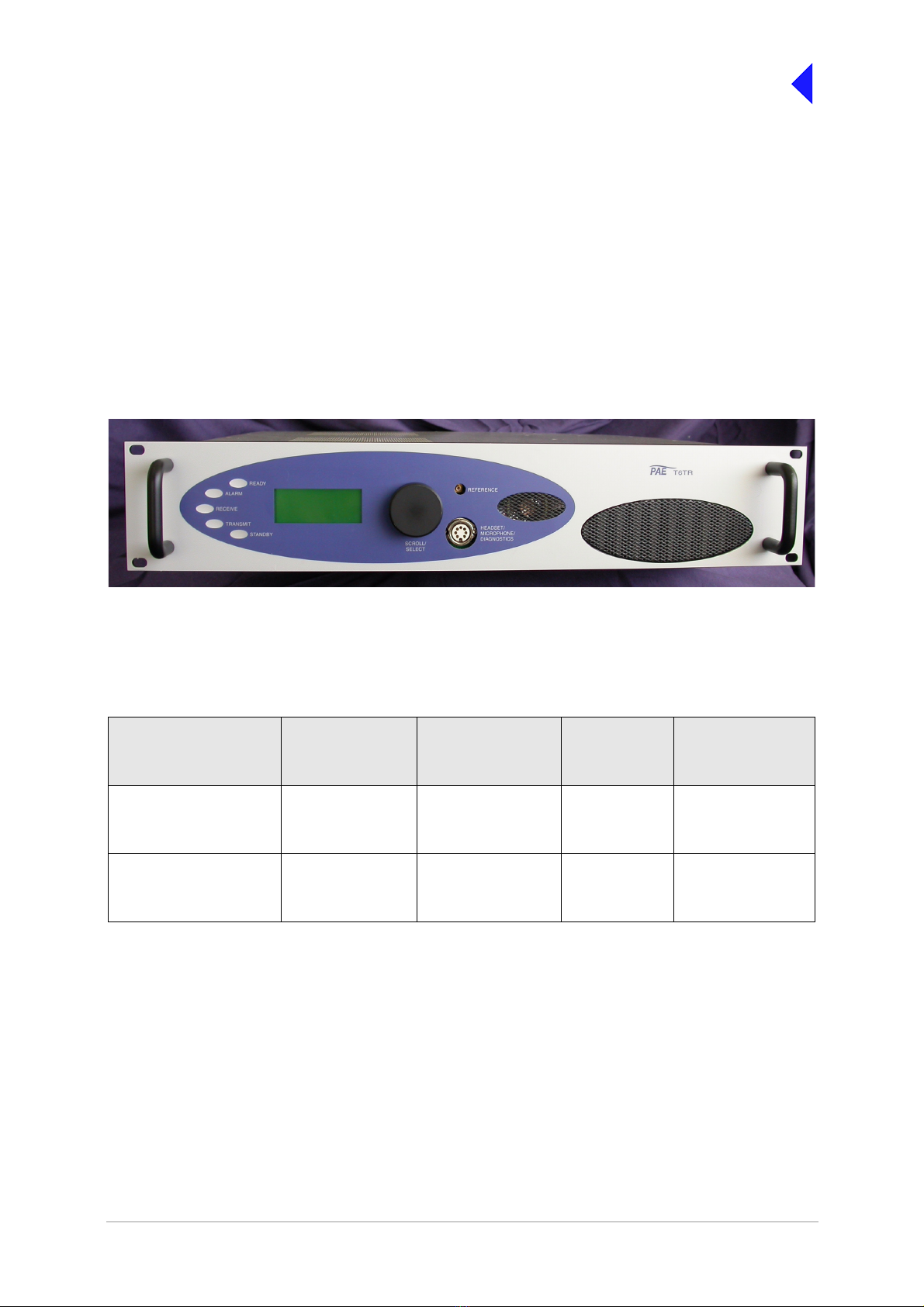
T6TR VHF 50 W Transceiver Page 3 Introduction
Back to Transceiver
Main Page
Frequency Selection
T6 radios operate with 8.33 kHz and 25 kHz channel spacing. The radios recognize frequencies entered
in ICAO format and automatically adjust to the correct channel spacing. For multichannel operation up
to 100 preset frequency channels can be stored in the radio for immediate recall; any combination of
8.33 kHz and 25 kHz channel spacing can be stored. Any valid operating frequency can be selected from
the radio’s front panel or a compatible remote control equipment.
Operating Parameters
The transceiver’s operating parameters are set using the front panel multi-purpose Scroll/Select switch,
or by using the Park Air Virtual Front Panel (VFP) software in conjunction with a Personal Computer (PC).
Virtual Front Panel
The Virtual Front Panel (VFP) software supplied on CD with the radio is compatible with any PC or laptop
running Windows 2000™ or Windows XP™. The VFP allows changes to a radio’s settings and channel
information, it displays the current BIT state, displays BIT history, allows security locks to be set, and
provides maintenance facilities. A typical VFP presentation is shown in Fig 2. Using the VFP has several
advantages over setting a radio from the front panel; these are:
A profile of the operational settings and channel information can be created, stored on disk, and
then recalled to download into other radios.
A print out of the radio’s profile can be made from the VFP.
The front panel controls can be locked. Front Panel Lock is available only when using the VFP.
Fig 2 Typical VFP Presentation

Back to Transceiver
Main Page
Intentionally Blank

Back to Transceiver
Main Page
Specification
This topic gives the specification applicable to the T6TR VHF 50 W Multimode Transceiver
operating in AM modes, Mode 2 and Mode 3.
All radios operate in AM-Voice mode. Additional software must be loaded to allow AM-MSK,
Mode 2 and Mode 3.

T6TR VHF 50 W Transceiver Page 2 Specification
Back to Transceiver
Main Page
General Specification
The general specification applies to a transceiver irrespective of the selected operating mode.
Variants
The T6TR VHF Multimode Transceiver is available in two variants as listed in Table 1.
Number of Channels
All variants The transceiver can store a single frequency or up to 100 frequencies
in its channel memory without the need for additional hardware.
Frequency Accuracy
All variants except HS Better than 1 ppm.
Power Requirements
The transceiver operates from an ac mains supply, or a dc input supply. When both supplies are
connected, the dc input acts as an automatic backup for the ac mains.
ac input supply The transceiver operates from a 48 to 62 Hz single-phase ac supply
and automatically adjusts to operate from any supply voltage ranging
from 110 Vac to 230 Vac ±10%. The power consumption figures are
given in Table 2.
dc input supply The transceiver operates from a dc input supply between 21.6 and
32 V (measured at the radio’s input). Current loading is given in
Table 2.
Table 1 Transceiver Variants
Description Part Number Frequency Range Special Applications
50 watt standard frequency
coverage transceiver
B6550/NB/50 118 to 136.975 MHz Supports 2, 3 and 4-offset
carrier operation
50 watt extended frequency
coverage transceiver
B6550/WB/50 112 to 155.975 MHz Supports 2, 3 and 4-offset
carrier operation
Table 2 Power Consumption
Transmitting or
Receiving
Normal Operation
ac dc
Transmitting 500 VA 12 A
Receiving 70 VA 1.2 A

T6TR VHF 50 W Transceiver Page 3 Specification
Back to Transceiver
Main Page
Dimensions and Weight
The dimensions and weight of the transceiver are:
Width 483 mm (19 inches).
Height 88.9 mm (3.5 inches). The height occupies 2U of equipment cabinet
space.
Depth 430 mm (16.9 inches) measured from front panel to rear panel.
Depth 450 mm (17.8 inches) measured from front panel to rear of fan.
Weight 13.5 kg (29.76 pounds).
Environmental
Temperature range The transceiver operates to specification across the temperature
range of -20 to +55°C.
The transceiver can be stored at temperatures ranging from
-30 to +70°C without causing any damage.
Humidity The transceiver operates to specification at a relative humidity
between 5% and 90% non-condensing.
Altitude The radios operate to specification up to 15,000 feet. Additionally the
equipment is capable of storage at altitudes up to 50,000 feet without
damage.
Shock and vibration The radios comply with shock and vibration protection MIL-STD-810E,
method 516.4, procedure VI - Bench Handling.
Ventilation The transceivers are cooled by an integral fan, which normally runs at
half speed. At an RF PA temperature of 45°C this is increased to full
speed and at 40°C it reduces to half speed again.
The transceivers also include an additional temperature controlled fan
contained in the power supply.
Warm up time All variants are fully operational to specification within 20 seconds
after switch on.

T6TR VHF 50 W Transceiver Page 4 Specification
Back to Transceiver
Main Page
AM Modes
Introduction
The transceiver can operate in AM-Voice mode and AM-MSK mode. The following specifications apply
to both modes unless stated otherwise.
Transmit RF Characteristics
Output Impedance
50 ohms.
RF Power Output
The RF carrier output power is adjustable in 1 W steps from 5 W to 50 W (as an option, the maximum
selectable power can be limited). Output power is automatically controlled under the following conditions:
Frequency range Variations in power remain within -0 to +1 dB over the operational
frequency range.
Low supply voltage Loop error can reduce power progressively by up to ±1 dB for supply
voltages between 24 Vdc and 32 Vdc.
High VSWR Loop error can reduce power progressively by up to 3 dB. Variations
in power remain within ±1 dB into a VSWR of up to 2.5:1. At VSWRs
greater than this the output power may be reduced by 10 dB ±1 dB.
High RF PA temperature If the RF PA temperature sensor exceeds 80°C the output power is
reduced by 3 dB ±1 dB. If the RF PA temperature sensor exceeds
90°C the transceiver is de-keyed and automatically re-keyed at 70°C.
Rise time The power rise time from a keying contact to 90% of full power is less
than 20 ms.
Duty Cycle
All variants 100% continuous operation.
Channel Spacing
AM-Voice The transceivers are capable of both 25 kHz channel spacing and
8.33 kHz channel spacing.
AM-MSK 25 kHz only.
Offset Carrier
AM-Voice The T6TR is capable of offsetting the carrier frequency to provide 2, 3
and 4-carrier offset.
AM-MSK Not available.
Harmonic Outputs
All variants Second harmonic outputs are less than -36 dBm, third harmonic
outputs are less than -46 dBm and fourth harmonic outputs and above,
up to 4 GHz, are less than -56 dBm.

T6TR VHF 50 W Transceiver Page 5 Specification
Back to Transceiver
Main Page
Spurious Outputs
All variants The spurious outputs are less than -46 dBm for modulation depths up
to 90%, measured at greater than 500 kHz from carrier in the
frequency range 9 kHz to 4 GHz. There are no coherent spurious
outputs above the spectral mask at less than 500 kHz.
Intermodulation
All variants Intermodulation products, caused by an interfering signal with the
same power as the transceiver isolated by 30 dB, are at least -40 dBc
at ≥±150 kHz and -50 dBc at ≥±500 kHz.
Transmit Modulation Characteristics
The transceiver transmit modulation characteristics are as follows:
Mode
AM-Voice The AM-Voice mode uses Double Side Band (DSB) Amplitude
Modulation (AM) full carrier, emission designator 6K80A3EJN for
25 kHz channels and 5K00A3EJN for 8.33 kHz channels.
AM-MSK The AM-MSK mode uses Double Side Band (DSB) Amplitude
Modulation (AM) full carrier, emission designator 13K0A2DJN.
Modulation Depth
All variants The transmitter modulation can be set to a maximum of 95%. This
eliminates any interference in adjacent channels at 25 kHz or
8.33 kHz channel spacing.
Hum and Noise
All variants The hum and noise is more than 45 dB below the signal level for line
input levels <-13 dBm, and more than 50 dB below the signal level for
line input levels ≥−13 dBm, for a carrier modulated by a 1 kHz signal
with a modulation depth of 90%.
Frequency Response
25 kHz channel spacing The variation in frequency response with reference to a 1 kHz signal
is within +0.5 dB and -1.5 dB across the frequency range 300 to
3400 Hz. The response is also less than -20 dB at 100 Hz and below,
and less than -30 dB at 4 kHz and above.
8.33 kHz channel spacing The variation in frequency response with reference to a 1 kHz signal
is within +0.5 dB and -1.5 dB across the frequency range 350 Hz to
2500 Hz. The response is also less than -10 dB at 100 Hz and below,
and less than -30 dB at 3200 Hz and above.

T6TR VHF 50 W Transceiver Page 6 Specification
Back to Transceiver
Main Page
Distortion
25 kHz channel spacing The total harmonic distortion is less than 5% due to signals with a
modulation depth of 90%, within the frequency range 300 Hz to
3400 Hz.
8.33 kHz channel spacing The total harmonic distortion is less than 5% due to signals with a
modulation depth of 90%, within the frequency range 350 Hz to
2500 Hz.
Residual FM
All variants For a test signal of 1 kHz set at 80% modulation depth applied to the
line input of the transceiver, the unwanted peak frequency modulation
does not exceed ±500 Hz.
VOGAD
AM-Voice The VOGAD has an operational range of 30 dB. The VOGAD can be
disabled.
AM-MSK The VOGAD is disabled.
Mute
AM-Voice The mute level is set at 15 dB below the average speech line level
setting. The mute can be disabled.
AM-MSK The mute is permanently disabled.
Differential Group Delay
AM-MSK only There is a 60 µs of differential group delay for signals in the range
1200 to 2400 Hz.
Transmit Control
Transmit control characteristics are as follows:
AM-Voice Audio Inputs
Voice can be connected to the transceiver via the front panel microphone connector. Voice can also be
connected via the 600 ohm balanced line inputs. Line level setting from -30 to +10 dBm.
AM-MSK Input
AM-MSK data is connected to the transceiver via an external modem connected to the line inputs.
PTT Timeout
The timeout period is adjustable from 2 to 510 seconds in 2 second steps or can be disabled.

T6TR VHF 50 W Transceiver Page 7 Specification
Back to Transceiver
Main Page
Receive RF Characteristics
RF Input
50 ohms.
Sensitivity
Between 118 and 136.975 MHz 12 dB SINAD for -107 dBm (1 µV) 30% modulated.
Between 112 and 117.975 MHz: 12 dB SINAD for -105 dBm (1.25 µV) 30% modulated.
Between 137 and 155.975 MHz: 12 dB SINAD for -105 dBm (1.25 µV) 30% modulated
Note:
All references to SINAD in this document include ITU-T recommendation P.53 weighting.
When operating the transceiver in combined T/R antenna configuration, the sensitivity figures
are degraded by 1 dB.
The transceiver has a nominal 6 dB reduced sensitivity feature to improve co-location
performance when maximum sensitivity cannot be realised because of strong unwanted
signals. This is in the form of a 6 dB RF pre-attenuator.
Channel Spacing
AM-Voice 25 kHz, or 8.33 kHz.
AM-MSK 25 kHz.
IF Selectivity
25 kHz channel spacing At ±11 kHz from the centre frequency, the signal is attenuated by less
than 6 dB. At ±25 kHz from the centre frequency, the signal is
attenuated by more than 80 dB.
8.33 kHz channel spacing At ±3.5 kHz from the centre frequency, the signal is attenuated by less
than 6 dB. At ±8.33 kHz from the centre frequency, the signal is
attenuated by more than 70 dB (60 dB using the ETSI test method). At
±25 kHz from the centre frequency, the signal is attenuated by more
than 80 dB.
Unwanted Signal Suppression
Intermod signal suppression The intermodulation signal suppression is 80 dB or greater (reference
12 dB SINAD) for two unwanted signals spaced 100 kHz
(unmodulated) and 200 kHz (30% modulation) from the channel
frequency.
Blocking ratio 95 dB or greater (reference 12 dB SINAD and degraded by 6 dB) in
the presence of an unmodulated unwanted signal spaced at 200 kHz
from the channel frequency.
105 dB or greater (reference 12 dB SINAD and degraded by 6 dB) in
the presence of an unmodulated unwanted signal spaced at 3 MHz
from the channel frequency.
Cross-modulation rejection 95 dB or greater (reference 30 dB SINAD and degraded by 10 dB) in
the presence of a 30% modulated unwanted signal spaced at 200 kHz
from the channel frequency.
105 dB or greater (reference 30 dB SINAD and degraded by 10 dB) in
the presence of a 30% modulated unwanted signal spaced at 3 MHz.

T6TR VHF 50 W Transceiver Page 8 Specification
Back to Transceiver
Main Page
Spurious signal suppression The spurious signal suppression (reference 12 dB SINAD) is 80 dB, or
greater (typically >100 dB) for a 30% modulated unwanted signal. This
applies to unwanted signals up to 2 GHz and spaced by more than two
channels from the tune frequency.
Above 2 GHz, spurious signal suppression is 70 dB or greater
(typically >100 dB).
Image response rejection is 80 dB or greater.
IF response rejection is 80 dB or greater.
Interfering signals At least 6 dB SINAD is achieved for a wanted -87 dBm signal
modulated with a 1 kHz tone 30% in the presence of two -5 dBm
interfering signals. The two signals are both FM modulated, one with
a 19 kHz tone 7.5 kHz deviation at 107.9 MHz and varied by ±4 kHz
the other with a 19.1 kHz tone 7.5 kHz deviation with its frequency
chosen such that one of the 3rd order products is located on the
chosen receive frequency.
Antenna Radiation
All variants Radiation at the antenna socket is less than -81 dBm, typically less
than -100 dBm, within the frequency range 9 kHz to 4 GHz.
Maximum RF input
All variants The transceiver can withstand an RF input of +36 dBm for 20 seconds,
and a continuous +27 dBm input, without causing damage.
Receive Modulation Characteristics
The receive modulation characteristics are as follows:
Mode
AM-Voice The AM-Voice mode uses Double Side Band (DSB) Amplitude
Modulation (AM) full carrier, emission designator 6K80A3EJN for
25 kHz channels and 5K00A3EJN for 8.33 kHz channels.
AM-MSK The AM-MSK mode uses Double Side Band (DSB) Amplitude
Modulation (AM) full carrier, emission designator 13K0A2DJN.
Frequency Response
25 kHz channel spacing The variation in frequency response with reference to a 1 kHz signal,
is within +1 dB and -2 dB across the frequency range 300 to 3400 Hz.
The response is less than -20 dB for frequencies at or below 100 Hz,
and less than -30 dB at 4 kHz and above.
8.33 kHz channel spacing The variation in frequency response with reference to a 1 kHz signal,
is within +1 dB and -2 dB across the frequency range 350 to 2500 Hz.
The response is less than -10 dB for frequencies at or below 100 Hz,
and less than -30 dB at 4 kHz and above.

T6TR VHF 50 W Transceiver Page 9 Specification
Back to Transceiver
Main Page
Distortion
25 kHz channel spacing For RF input signals between -53 dBm and +10 dBm, the total
harmonic distortion is less than 5% within the frequency range 300 Hz
to 3.4 kHz when the modulation depth is between 30 and 90%.
8.33 kHz channel spacing For RF input signals between -53 dBm and +10 dBm, the total
harmonic distortion is less than 5% within the frequency range 350 Hz
to 2.5 kHz when the modulation depth is between 30 and 90%.
Wanted Signal Dynamic Range (RF AGC)
For a 90% modulated on-channel signal, a change in signal level from -107 dBm to +10 dBm produces
less than a 3 dB change in audio output. On-channel signals modulated at 90% up to a level of +17 dBm
achieve at least 10 dB SINAD.
The AGC attack time is less than 40 ms and the decay time is less than 50 ms for a 40 dB step input.
Audio AGC
AM-Voice The audio AGC compresses a 30% to 90% variation in input
modulation depth to an audio output power change of 1 dB or less.
The audio output level is maintained at the equivalent of 90%
modulation. Audio AGC can be disabled.
AM-MSK The audio AGC is permanently disabled.
Squelch
The receiver has a noise compensated carrier operated squelch. It has a carrier adjustment range of -114
to -60 dBm without the RF pre-attenuator selected (these levels are increased by the value of the RF pre-
attenuator when it is selected) and provides greater than 60 dB of quieting.
Attack time is <20 ms for a signal rising 10 dB above the squelch setting
Release time is <20 ms for a signal falling 10 dB below the squelch setting
Hysteresis is 2 to 4 dB.
The squelch has a noise compensation disable facility to provide carrier only operation.
The squelch has a carrier override enable facility, which is preset at 10 dB (±2 dB) above the current
squelch setting.
The squelch can also be defeated.
The squelch is independent of the audio output control.
Receive Control
AM-Voice Audio Outputs
The transceiver’s outputs are the remote 600 ohm balanced audio line, the headset output and the
loudspeaker. Line level output is adjustable between -30 and +10 dBm.
AM-MSK Audio Output
AM-MSK data is connected to an external modem through the remote audio line output.

T6TR VHF 50 W Transceiver Page 10 Specification
Back to Transceiver
Main Page
Mode 2
Mode 2 parameters are identical to AM-Voice mode with the following exceptions.
Transmit RF Characteristics
RF Power Rise Time
The transceiver produces more than 90% of full power output within the first 2 symbols of the power
stabilization segment, which is the first segment of the training sequence and consists of 4 symbols each
representing 000.
RF Power Decay Time
The output power decays by more than 20 dB within 2.5 symbols of the middle of the final symbol.
Channel Spacing
25 kHz channel spacing only.
Transmit Modulation Characteristics
Mode
Mode 2 uses Carrier Sense Multiple Access (CSMA) differentially encoded 8-phase shift keying
(D8PSK), using a raised cosine filter with α=0.6 (nominal value), emission designator 14K0G1DE.
Information is differentially encoded with 3 bits per symbol transmitted as changes in phase rather than
absolute phase. The data stream is divided into groups of 3 consecutive data bits, least significant bit
first. Zeros are padded to the end of transmissions if needed for the final channel symbol.
Modulation Rate
The symbol rate is 10,500 symbols/second (±0.005%), resulting in a nominal bit rate of 31,500 bits/s.
RMS Phase Error
The RMS phase error is less than 3°. The error vector magnitude is less than 6%.
Phase Acceleration
The total frequency change during the transmission of the unique word is less than 10 Hz. After this, the
phase acceleration is less than 500 Hz/s.
Receive RF Characteristics
Sensitivity
The transceiver has a sensitivity better than -102 dBm for 1x10⁻³ Bit Error Rate (BER) with Reed
Solomon decoding off.
Channel Spacing
Mode 2 channel spacing is 25 kHz.
Table of contents