Air Comm Systems, Inc. Page 7
ACS 2080-300 Operations and Installation Manual
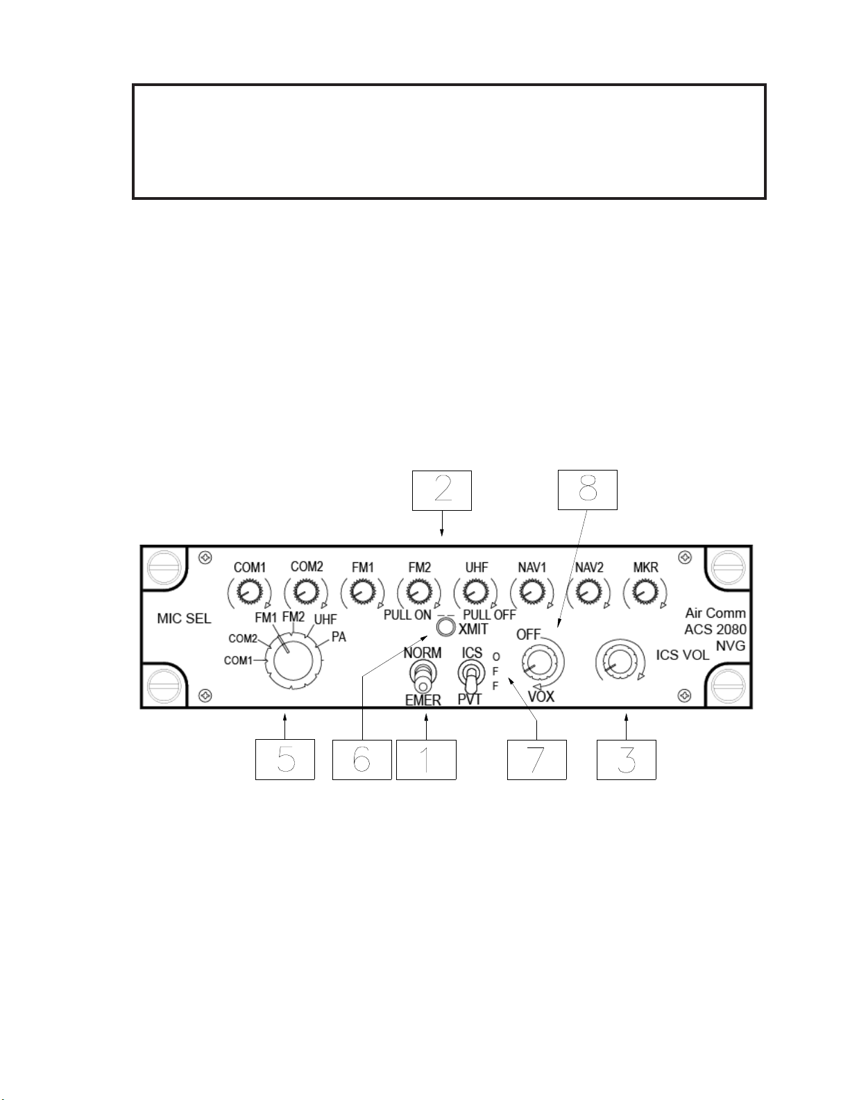
Front Panel Controls
( See Figure 1 — Page 8 for pictorial )
n5 - Mic Selector
This rotary switch performs three functions simultaneously. It (a) connects the mic to the selected transmitter
(b) selects the associated keyline, and (c) selects the associated audio (if not already selected using the
audio select-mute volume pot). This allows properly monitoring before transmitting.
n 6- Transmit Indicator
When the transmit key is activated this indicator lights up show that the audio panel is in the transmit mode.
n7 - ICS Switch
This switch selects the ICS mode. In the "up" position the audio panel is connected to the common ICS
buss. This enables the audio panel to communicate with any other audio panels also connected to the
common ICS buss. In the “center” position (OFF) the audio panel is disconnected from all other panels.
In the “down” position (PVT) the audio panel is connected to the common PVT ICS Buss. This enhances the
audio panel to communicate with audio panels also connected to the common PVT buss. An emergency
switch can be installed for pilot to connect all audio panels to override buss.
n8- VOX Control
The high-power VOX is controlled by this knob. In order to use the VOX feature, the ICS ON/OFF/PVT
toggle switch must either be in the “ON” or “PVT” position. If the toggle switch is in the “OFF” position, the
Audio Mixer Panel is isolated from the ICS buss, and no ICS communication is possible. Once the ICS
switch is in the “ON” or “PVT” position, the VOX can be activated by turning the knob clockwise past the
On/Off detent and threshold set to activate with voice.
The moment you begin talking the VOX circuitry activates and relays your voice transmission. When you
stop speaking the VOX circuit turns off to reduce unwanted background noise. Turning the knob clockwise
adjusts the threshold. If the knob is turned fully clockwise the VOX circuit will always be active and you will
hear background noise. If the knob is adjusted just past the On/Off detent then the VOX circuit cannot be
activated and you will revert to normal keyed ICS. Adjust the threshold level to match the ambient noise
conditions of the aircraft at the time for proper operation.
While in the VOX mode, if you wish to quickly isolate yourself from the ICS buss, you simply put the ICS
ON/OFF/PVT toggle switch in the “OFF” position.


 User manual")