Air Comm Systems, Inc. Page 6
ACS 300A-100 Installation and Operations Manual Front
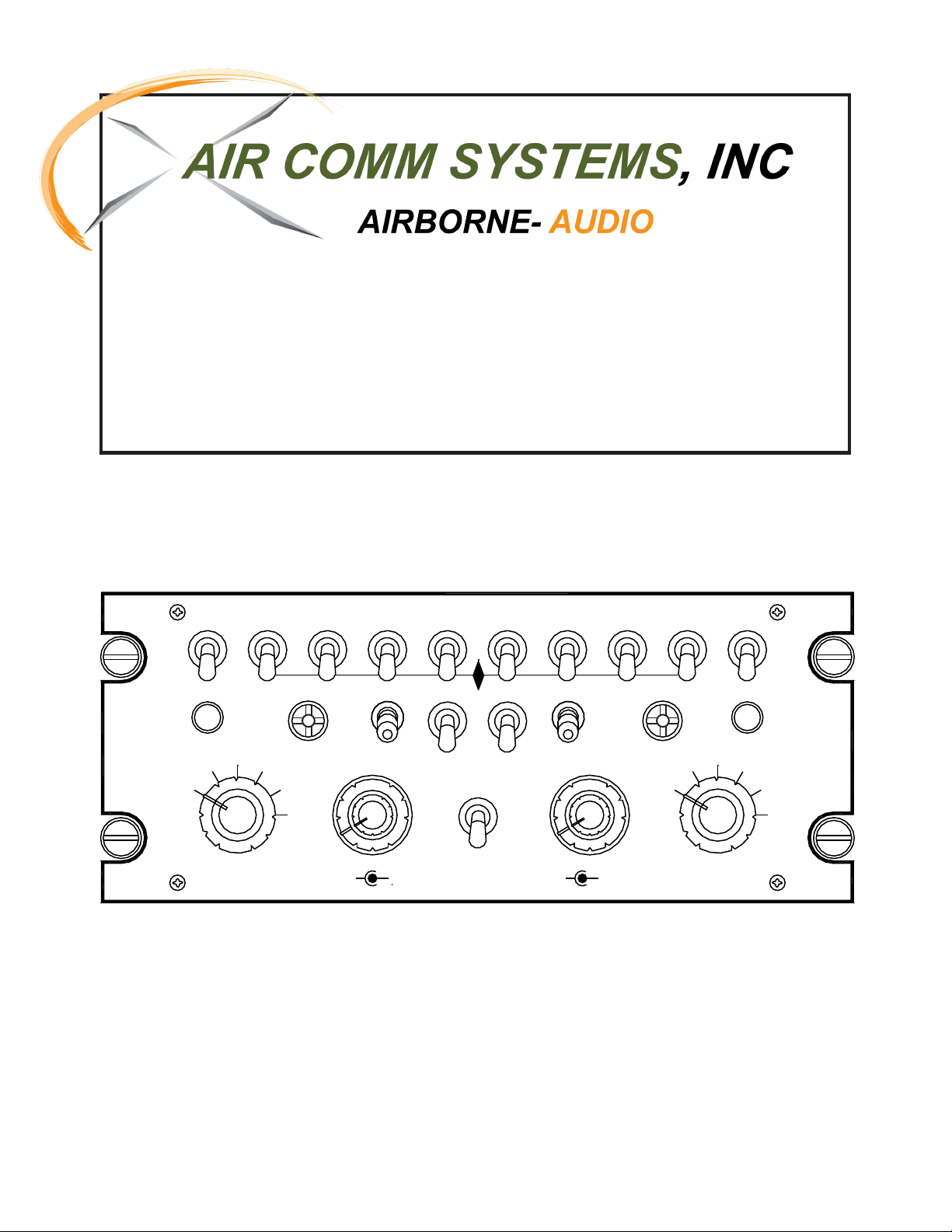
Panel Controls
(
See
Figure
1
—
Page
8
for
pictorial
)
nDescription
The ACS 300A -100 Dual Audio Mixer Panel is a compact, lightweight unit which
provides full audio control and ICS support for Pilot and Co-pilot or observer positions in
the aircraft. It has the capability to provide each user with 6 receive audio selections, 6
transmitter selections, Normal and HOT (Hands Free) ICS, and full headphone audio
and ICS volume control. In addition, an internal expansion slot accepts a plug-in module
(optional) which can give the unit an additional 6 positions of ICS capability, 2 of which
also have TX capability.
n1- Norm - Emer Switch
This switch controls the operation of the audio panel in the event of an audio amplifier
failure. In the “up” position (NORM) the audio panel is in normal operating mode. In the
“down” position (EMER) the unit is in the emergency mode. During Emergency
operation, with a receive audio switch in the "down" position the mic select rotary switch
selects the mic, key, and unamplified audio in the event of an audio amplifier failure. The
side in emergency mode will not have incoming ICS.
n2 - Receive Audio Select-Mute Switches
Normal operation - In the “up” position the audio selected is summed with any other
audios selected into the headphone amplifier. It also selects or mutes cross side tone.
In the “down” position the audio selected is muted. Cross side tone is also muted.
Emergency operation - In the "down" position the mic select rotary switch selects the
mic, key, and unamplified audio in the event of an audio amplifier failure. The side in
emergency mode will not have incoming ICS.
n3 - Volume Controls
These concentric knobs adjust headphone volume. The larger one adjusts the radio
volume while the smaller one adjusts the intercom (ICS) volume. Clockwise rotation
increases the volume - counter clockwise rotation decreases the volume. To set volume,
transmit on the radio and set the side tone level slightly on the low side so you will have
a tendency to talk up and have higher modulation. Then set the radio volume for
comfortable listening. In the event of excessive or inadequate receiver volume the pots
located on the rear of the unit may be adjusted for the proper level. (See Figure 2 on
page 8).


 User manual")