Air Force F-19 Gen3 User manual

Owner’s Manual
Issue: NHS OCT 2021
Start: S/N AF19-16270

©2021 Air Force Hover Mowers. All rights reserved.
Printed in the United States of America

Table of Contents
Page| 3
Contents 3
Specifications 4
Introduction 5
Warranty Information 6
Safety Symbols 7
Safety Precautions 8
Training 8
Preparation 8-9
Operation 9-10
Maintenance & Storage 10-11
Machine Assembly 12
Fuel & Oil Recommendations 12
Oil Type 12
Fuel Type 12
Before Starting the Machine 13
Prevent Engine Damage 13
Oil Level Check 13
Fueling the tank 13
Engine Exploded Diagram 14-15
Engine Parts List 16-17
Mower Parts List 18
Mower Exploded Diagram 19
Operating the Machine 20-21
Starting the Machine 20
Cutting Flat Landscapes 21
Cutting Slopes and Banks 21
Stopping the Machine 21
Cutting Height Adjustment 21
Machine & Engine Maintenance 22-25
Engine diagrams 22
Cleaning the Air Filter 22
Servicing the Spark Plug 22
Muffler 23
Oil Maintenance 23
Keeping the Engine Clean 23
Deck Housing 23
Nuts and Bolts 23
Cutting System Maintenance 24
Sharpening the SS Blades 24
Flexiblade Cutting System 25
Mower Storage 25
Maintenance Schedule 26
Troubleshooting 27
Warranty Registration Back Page
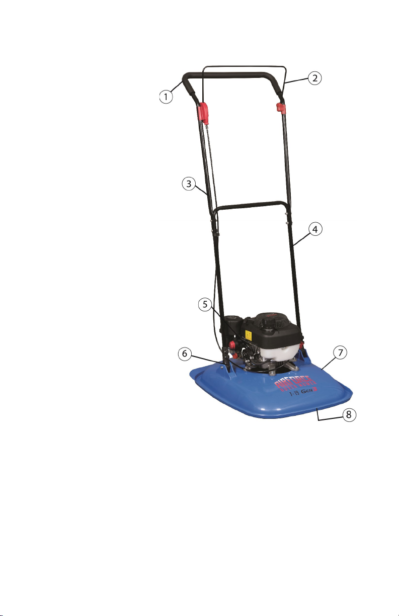
Main Features:
(1) Padded handles
(2) Positive pressure keeps
OPC locked in place
(3) 53” Handle for longer reach
(4) Heavy gauge steel handles
(5) Double tall air filter
(6) Extra thick handle mounts
(7) Nylon injected Polymer deck
(8) 14” Impeller for increased lift
Model F-19
Engine Ducar
Engine Type DVO-150
Engine Speed 3600 rpm
Fuel Type Unleaded
Fuel Capacity 0.24 gallons
Engine Oil Type SAE 10W-30
Oil Sump Capacity 0.5 quarts
Cutting Width 19 inches
Dry Weight 33 lbs
Specifications
Page| 4

Thank you for purchasing the Air Force Hover Mower. The following pages
are to give you information about maintenance, operation, safety and
specifications instructions regarding your new mower. We strongly
recommend reading the manual before your first use.
Important: Familiarize yourself with all controls, operations and regular
maintenance points before your first use. If you require clarification, please
consult your local Authorized Dealer who can assist you further.
The Air Force Hover Mower is designed for cutting grass and low-to-the-
ground vegetation. Any other use is considered contrary to the intended use
of the machine. Strict adherence and compliance with the conditions of
operation, repair and service as stated in this manual are required.
Precautions and safety tips found in this manual are standards that are
generally recognized and must be observed at all times. Any modifications to
this machine will relieve the manufacturer of liability for any resulting
damage or injury.
Air Force Hover Mowers should only be operated, repaired or serviced by
persons knowledgeable about the machines and familiar with their safety
features. Correct operation and maintenance will ensure a long service of the
machine.
All references to the left and right side of the machine are as viewed from
behind the mower in the operator’s position.
This manual is written based on information available at the time of
publications. Air Force reserves the right to amend the product,
specifications, and information within the manual without prior notification.
Introduction
Page| 5

LIMITED WARRANTY
The manufacturer warrants to the original purchaser that this unit shall be
free from defect in material and workmanship under normal use and service
for a period of one year from the date of purchase. The engine carries a 90
day commercial warranty.
To qualify for the full benefit of the Air Force warranty, the warranty
registration card must be returned to the distributor. If your selling dealer
does not offer this service, please fill out and return the enclosed warranty
registration card. Subject to the conditions and exclusions noted in the
Limited Warranty, we shall at our option, repair or replace any warranty part
during the applicable period. If you are in doubt or experience any difficulty,
please consult your Authorized Dealer for clarification.
A 90-day warranty period applies to those items which are subject to normal
wear and tear: blade systems, cables, etc.
This warranty does not apply to any unit that has been tampered with,
altered, misused, abused or used for hire, and will become invalid if
non-genuine parts are fitted at any time. This warranty does not cover minor
mechanical adjustments unless they are due to defective material or
workmanship. Consult the Owner’s Manual or your Authorized Dealer for
assistance when making these adjustments.
To make a warranty claim, contact your Authorized Dealer with your proof
of purchase, which states the machine serial number and date of purchase.
The dealer will, at our option, repair or replace any warranty part within the
duration of the warranty period. If your dealer does not provide services,
please contact the distributor directly with your proof of purchase.
This limited warranty gives you specific legal rights and is in addition to any
statutory rights to which you may be entitled; your statutory rights are not
affected by this warranty.
US / CANADA ONLY: Information regarding Authorized Dealers can be
obtained by contacting Seago International.
Web: www.seagousa.com
Phone: (800) 780-9889
Warranty
Page| 6

Safety Symbols
Page| 7
Manual: Read the instruction manual before using machine.
Use the Manual: Refer to the manual when making any
adjustments or repairs to the machine.
Spark Plug: Disconnect the spark plug when doing any
work on the machine.
Hot Surface: Be aware of the hot surfaces of your machine
during and after use.
Protective Gear: Always wear protective ear and eye gear
when operating the machine.
Safe Distancing: Keep a safe distance of pedestrians and pets
while the machine is in operation due to flying debris.
Safe Footing: Be aware of your footing and wear the proper
footwear when operating the machine on an incline.
Warning: Always be alert of possible hazards and your work
environment.

Safety Precautions
Your machine is perfectly safe if used correctly. Failure to observe the
following precautions may result in serious injury.
Training
Read the Owner’s Manual and other informational material that came with
your new mower. If the operator or mechanic cannot read English, it is the
owner’s responsibility to explain this material to them.
Become familiar with the safe operation of the mower, operator controls, and
safety signs.
All operators and mechanics should be trained. The owner is responsible for
training all users.
The owner/operator is responsible for and can prevent accidents or injuries
occurring to themselves, others and property by adhering to the safety
instructions in this manual.
Never let children or untrained people operate or service the mower. Local
regulations may restrict the age of the operator.
Preparation
While using the machine, always wear substantial protective footwear and
long pants. Do not operate the equipment when barefoot or wearing open-toe
shoes.
Wear appropriate clothing including hard hat, safety glasses and hearing
protection. Long hair, loose clothing or jewelry may get tangled in moving
parts.
Any person within 6 feet of machine
should wear protective clothing to
prevent injury,
Evaluate the terrain to determine what accessories and attachments are
needed to properly and safely perform the job. Only use accessories and
attachments approved by Air Force.
Inspect the area where the equipment is to be used and remove all objects
such as rocks, toys, and wire which can be thrown by the machine.
Page| 8

Safety Precautions
Use extra care when handling gasoline and other flammable fuels. Vapors are
explosive.
(a) Use only approved fuel containers
(b) Never remove fuel cap or add fuel when the engine is operating
(c) DO NOT SMOKE while operating the machine
(d) Never refuel or drain the machine indoors
(e) Always use fresh non-ethanol fuel. Stale fuel can block the
carburetor and cause leaks.
Check that the Operator Presence Control (OPC) and safety switches are
attached and functioning properly.
Keep all parts in good working condition and all hardware tightened.
Replace all worn or damaged decals.
Do not use near children or pets.
A damaged cutting device and/or impeller must be replaced. Before use,
always visually inspect the cutting system to ensure that it is in good
condition. Do not operate with an out-of-balance cutting system or impeller.
Operation
Do not operate the engine in an enclosed space where exhaust fumes (carbon
monoxide) can collect. Refuel outdoors only and do not smoke while
refueling.
Do not operate the machine under the influence of alcohol or drugs.
Always pull the starter cord slowly until resistance is felt. Then pull the cord
rapidly to avoid kickback and prevent hand or arm injury. Ensure that feet
are away from the cutting system.
Operate only in daylight or good artificial light, keeping away from holes
and hidden hazards.
Avoid operating the machine in wet grass. Be sure of your footing while
using this product, especially when backing up. Reduced footing could cause
slipping.
Walk, never run when operating the Air Force Hover Mower.
Page| 9

Safety Precautions
Operate across the face of slopes, never up and down. Slow down and use
extra care when making turns or changing direction on slopes. Be sure to
travel in the recommended direction on slopes. Turf conditions can affect the
machine’s stability. Use caution while operating near drop-offs.
Never raise the deck with the blades in motion. Stop the engine before
moving the machine across areas other than grass.
Never operate without the safety guards in place.
Do not change the engine governor settings or over speed the engine.
Never touch the exhaust/exhaust guard or cooling fins with the engine is hot.
Stop engine and disconnect the park plug lead:
(1) Before clearing blockages
(2) Before cleaning, checking or working on the machine
(3) After striking a foreign object. Inspect the machine for damage
and ensure necessary repairs are made before re-starting
(4) If the machine starts to vibrate abnormally (check immediately).
An out of balance cutting device causes severe vibration.
Stop engine:
(1) Whenever you leave the machine
(2) Before refueling
(3) Before cleaning between the engine and impeller
Keep hands and feet away from the cutting system.
To start, machine should ONLY be on flat ground, clear of debris.
Do not start on tables, carts, vehicles, utility work spaces, etc.
Maintenance & Storage
Disengage the drive, stop the engine and disconnect the spark plug. Wait for
all movement to stop before adjusting, cleaning or repairing. Keep hands and
feet away from moving parts.
Clean the cutting system, drive, muffler and engine of any grass or debris to
prevent fires. Clean up any fuel/oil spills.
Never store machine with gasoline in the tank within an enclosed area where
fumes may reach an open flame or spark.
Page| 10

Safety Precautions
Park the machine on level ground. Never allow untrained persons to service
the machine.
Remove the spark plug before attempting any repairs. Never check for a
spark when the spark plug is removed. Use an approved tester.
Keep all parts in good working condition and all hardware tightened.
Replace all worn or damaged decals. Always replace worn or faulty parts
with genuine Air Force Hover Mower parts.
Allow the engine to cool before storing in any enclosures. To reduce the risk
of fire hazard, keep the engine and the surrounding deck area free of grass,
leaves, and excessive grease.
Shut off fuel while storing or transporting. Do not store fuel near flames or
drain indoors.
If the fuel tank has to be drained, this should be done outdoors and when the
engine is cool.
Wear strong work gloves when removing and reassembling the cutting
device. Serious personal injury can occur without proper handling.
Never replace the cutting mechanisms with metal parts and only use cutting
mechanisms which are suitable for use at the operating speed of the machine.
Never start the engine with the air filter or the air filter cover removed.
Page| 11

Machine Assembly
Page| 12
Assembling the Machine
Step One: Lower Handlebar Assembly
To fit the lower handle to both sides, align the holes (footstop on the right
side) and insert the sleeves, bushes, bolts, washers and nuts as shown. (Uses
Deck/Handle Kit AF1210)
Step Two: Upper Handle Assembly
To fit the upper handle on both sides, align the holes and fit the bolts and
nuts. (Handle Securing Kit AF1207)
FUEL AND OIL RECOMMENDATIONS
Oil Type
When operating the Air Force Hover Mower, always use a high-quality
synthetic oil. Suggested classification is SAE 10W-30. Additives are not
recommended. To prolong the life of your engine, change the oil after the
initial first five hours of use.
Fuel Type
Clean, non-ethanol fuel is recommended. Purchase fuel in a 30-day quantity
to keep fresh fuel on hand.

Before Starting the Machine
Page| 13
Prevent Engine Damage
To prevent damage to the engine, the machine is shipped without any fluids.
The engine must be filled with the correct grade of oil and fuel before
starting the engine.
Oil Level Check
When checking the oil, keep the mower on a level surface. Remove the oil
cap, and wipe the dipstick with a clean cloth. Reinsert the dipstick without
screwing the cap back on, and remove it to check the oil level.
Correct oil level is when the brim of the liquid is at the UPPER LIMIT
mark on the dipstick. Do not overfill the engine with oil.
Fueling the tank
Fill to the base of the neck to allow for fuel expansion. Do not overfill the
fuel tank.
Ensure that the Operator Presence Control (OPC) Bail Arm moves freely and
returns to its resting position when released.

Page| 14
Exploded Engine Diagram
DV0-150 CPC
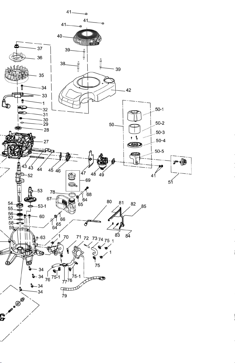
Page| 15

Page| 16
Engine Part List
NO PART Part name Quantity
1AF901 BOLT M6X16 11
2AF902 CYLINDER HEAD 1
3AF903 CYLINDER HEAD COVER GASKET 1
4AF904 ROCKER ARM ( SET OF 2) 1
5AF905 ROCKER ARM FASTENING BOLT ASSY (SET OF 2) 1
6AF906 INLET VALVE SPRING SEAT (SET OF 2) 1
7AF907 LIMIT PLATE ASSY 1
8AF908 VALVE SPRINGS (SET OF 2) 1
9AF909 INLET VALVE SPRING SEAT (SET OF 2) 1
10 AF910 THE VALVE PUSH ROD (SET OF 2) 1
11 AF911 THE VALVE LIFTER (SET OF 2) 1
12 AF912 INTAKE VALVE 1
13 AF913 EXHAUST VALVE 1
14 AF914 PISTON RING ASSY ( SET OF 4) 1
15 AF915 PISTON 1
16 AF916 PISTON PIN 1
17 AF917 PISTON PIN RETAINER (SET OF 2) 1
18 AF918 CONNECTING ROD COMPONENT 1
19 AF919 SPARK PLUG 1
20 AF920 EXHAUST GASKET 1
21 AF921 BOLT. STUD M6*77 (SET OF 2) 1
22 AF922 MUFFLER 1
23 AF923 MUFFLER HOUSING 1
24 AF924 LOCK NUT M6 (SET OF 2) 1
25 AF925 BRAKE ASSY 1
26 AF926 BOLT M6X18 1
27 AF927 CRANKSHAFT BOX BODY 1
28 AF928 CRANKSHAFT OIL SEAL 1
29 AF929 CIRCULAR PLATE 1
30 AF930 BREATHING VALVE SPRING 1
31 AF931 OIL RETURN CHAMBER COVER GASKET 1
32 AF932 OIL CHAMBER RETAINING PLATE 1
33 AF933 COIL 1
34 AF934 ENGINE BLOCK BOLT M6X25 8
35 AF935 FLYWHEEL 1
36 AF936 STARTER CUP 1
37 AF937 NUT M12X1.2 5 1
38 AF938 BOLT STUD.IGNITION COIL 1
39 AF939 STARTER COVER STUD (SET OF 2) 1
40 AF940 STARTER ASSEMBLY 1
41 AF941 NUT M6 5
42 AF942 ENGINE COVER 1
43 AF943 STUD M6X100 ( SET OF 2) 1
44 AF944 EXHAUST PIPE 1
45 AF945 INTAKE GASKET 1
46 AF946 HEAT INSULATION BLOCK 1
47 AF947 CARBURETOR GASKET 1
48 AF948 CARBURETOR ASSEMBLY 1

Engine Part List
Page| 17
NO PART Part name Quantity
49 AF949 AIR FILTER GASKET 1
50 AF950 AIR FILTER ASSEMBLY 1
50-1AF951 AIR FILTER COVER 1
50-2AF952 AIR FILTER 1
50-3AF953 SCREW 3
50-4AF954 AIR FILTER MIDDLE BRACKET 1
50-5AF955 AIR FILTER LOWER BRACKET 1
51 AF956 PRIMER PUMP ASSY (PIPE AND PUMP) 1
52 AF957 CRANKSHAFT 1
53 AF958 CRANKSHAFT ASSEMBLY 1
53-1AF959 CRANKSHAFT WASHER Ф14.2xФ21x0.5 1
54 AF960 CRANKSHAFT TIMING DRIVING GEAR 1
55 AF961 CRANKSHAFT WASHER Ф25.5xФ35x1 1
56 AF962 CRANKSHAFT OIL SEAL 1
57 AF963 OIL SEAL RETAINING WASHER 1
58 AF964 CLIP,FUEL LINE 1
59 AF965 CRANKCASE COVER / ENGINE FRAME 1
60 AF966 BOLT M6X12 (SET OF 2) 1
61 AF967 CENTRIFUGAL GOVERNOR GEAR ASSY 1
62 AF968 OIL GAUGE ASSY (62-1 THRU 62-4) 1
62-1AF969 O-RING 22*Ф2.5 1
62-2AF970 OIL DIPSTICK OUTSIDE COVER 1
62-3AF971 O-RING 26*Ф2.7 1
62-4AF972 OIL DIPSTICK 1
63 AF973 POSITIONING PIN OF CRANKCASE (SET OF 2) 1
64 AF974 WASHER, FUEL TANK (SET OF 2) 1
65 AF975 VIBRATION ISOLATION PAD (SET OF 2) 1
66 AF976 FUEL TANK BUSHING 1
67 AF977 FUEL TANK 1
68 AF978 BOLT M6X30 1
69 AF979 FUEL CAP ASSY 1
70 AF980 SPEED REGULATOR 1
71 AF981 SPEED REGULATING SPRING B 1
72 AF982 FUEL PUMP 1
73 AF983 FUEL FILTER 1
74 AF984 FUEL PIPE HOSE (p6.3x(p10x135 EPA 1
75 AF985 FUEL PIPE CLAMP <P10 2
75-1AF986 FUEL PIPE CLAMP 013 (SET OF 4) 1
76 AF987 FUEL PIPE (p6.3x(p12.7«50 EPA 2
77 AF988 FUEL COCK 1
78 AF989 TANK DAMPENING RING 1
79 AF990 AIR HOSE 1
80 AF991 SWINGING ROD 1
81 AF992 THROTTLE LEVER 1
82 AF993 COIL SPRING 1
83 AF994 PENDULUM STEM SEAL 1
84 AF995 COTTER PIN 1
85 AF996 CONTROL ARM 1

Page| 18
Mower Parts List
Key Part No Description Qty Notes
1AF1200 Upper Handle 1
2AF1241 OPC brake handle 1
3AF1240 OPC lever holder 1
4AF1239 Brake box and cable 1
5AF1245 Lower handle 1
6AF1207 Handle securing kit 1(Flange nuts
& bolts)
7AF1242 Handle Support RH 1Footstop side
8AF1243 Footstop w/ bolt 1
9AF1244 Handle support - LH 1
10 AF1210 Deck/handle kit 1Set of 2
11 AF1270 Deck/frame nut kit M6 G3 1Set of 6
12 AF1271 Deck G3 1
13 AF1272 Deck/frame bolt(M6 x 12.3)G3 1Set of 6
14 AF1276 Woodruff key G3 1
15 AF1217 Hub Spacer 1
16 AF1273 Drive hub G3 1
17 AF1274 Impeller G3 1
18 AF1220 Large Spacer 1
19 AF1221 Shaft spacer kit 1Set of 3
20 AF1222 Blade system disc 1
21 SE02412 SS blade kit w/ large washer 1Set of 3 each
22 SE18370 Bolt kit w/ small washer 1Set of 3 each
23 AF1225 Blade retaining spigot 1
24 AF1226 Washer 1
25 AF1275 Disc securing bolt G3 13/8*G24*75MM
26 SE00603 QC Blades 1Set of 6
*SE01206 QC Blades 1Set of 60
27 SE02214 Flexblade roll 185 ft roll
28 AF1223 String system disc 1
29 AF1250 Hi–Lift kit w/ clips 1
30 AF1251 Hi-Lift clip only 1
31 AF1264 Extension handle only 1 14in long
*AF1260 Extension handle kit 1#6,31 & cable
*AF1263 Extended brake cable 1Red box
*DV0-150
CPC Engine 1Not Shown
*AF1279 Air Force Decal G3 1Not Shown
*AF1230 Safety Decal 1Not Shown
*AF1231 Caution Decal 1Not Shown
*AF1232 QC Kit Complete #25,27,31
*AF1233 SS Kit Complete #25,26,27
*AF1280 Impeller Warning Decal 1Not Shown

Page| 19
Exploded Diagram

Page| 20
Operating the Machine
Starting the Machine
Step One:
Turn the petcock to the “on” position.
Step Two:
Press primer bulb NO MORE than 3 times. Move choke to the closed position.
Step Three:
Release the handlebar from the footstop. Hold the OPC Bail Arm to the
upper handle, place your foot on the right side of the deck and slightly
tilt the machine toward you. This position ensures the fuel is beginning
to circulate and makes cranking the engine easy. If starting the engine in tall
grass, you must slope the deck.
Pull the recoil starter rope lightly until you feel resistance, then pull briskly.
Return the starter grip gently. Once started return choke to open position.
Note: The OPC Bail Arm must be held firmly against the handlebar to start and
keep the engine running.
If it is released, the engine and blade system will stop.
To prevent damage, never pull the engine start grip
while the engine is running.
Table of contents
Other Air Force Lawn Mower manuals

Popular Lawn Mower manuals by other brands

Jacobsen
Jacobsen Turfcat II DW 220 Operator's manual and parts list

Snapper
Snapper CLP21650RV Safety instructions and operator's manual

Toro
Toro GrandStand 74534TE Operator's manual

Craftsman
Craftsman 917.255160 owner's manual

Craftsman
Craftsman 917.371950 owner's manual

Craftsman
Craftsman 917.28725 Operator's manual


Jonsered
Jonsered LT 2318 CMA instruction manual

Toro
Toro 03721 Operator's manual

Exmark
Exmark Metro MG16KA362 parts manual

Briggs & Stratton
Briggs & Stratton Prestige 1800 Series Operator's manual

Kubota
Kubota RCK60B-22BX Operator's manual

Scag Power Equipment
Scag Power Equipment SSZ-16BV Technical manual