manuals.online logo
Brands
  1. Home
  2. •
  3. Brands
  4. •
  5. Air King
  6. •
  7. Fan
  8. •
  9. Air King MFAS Owner's manual

Air King MFAS Owner's manual

www.airkinglimited.com
6728111 Rev. B 12-20 1 of 4
IMPORTANT INSTRUCTIONS - OPERATING MANUAL
INSTRUCTIONS IMPORTANTES – MANUEL D’OPÉRATION
SAVE THESE INSTRUCTIONS / CONSERVER CES INSTRUCTIONS
Inline Fan
Ventilateur d’évacuation en série
MFAS
READ AND SAVE THESE
INSTRUCTIONS
READ CAREFULLY BEFORE ATTEMPTING TO ASSEMBLE, INSTALL,
OPERATE OR MAINTAIN THE PRODUCT DESCRIBED. PROTECT
YOURSELF AND OTHERS BY OBSERVING ALL SAFETY INFORMATION.
FAILURE TO COMPLY WITH INSTRUCTIONS COULD RESULT IN
PERSONAL INJURY AND/OR PROPERTY DAMAGE!
RETAIN INSTRUCTIONS FOR FUTURE REFERENCE.
GENERAL SAFETY INFORMATION
When using electrical appliances, basic
precautions should always be followed to
reduce the risk of fire, electric shock and injury to person,
including the following:
WARNING: TO REDUCE THE RISK OF FIRE, ELECTRIC
SHOCK AND INJURY TO PERSON, OBSERVE THE FOLLOWING:
a) Use this unit only in the manner intended by the manufacturer.If you have questions,
contact the manufacturer.
b) Before servicing or cleaning the unit, switch power off at service panel and lock the
service disconnecting means to prevent power from being switched on accidentally. When
the service disconnecting means cannot be locked, securely fasten a prominent warning
device, such as a tag, to the service panel.
WARNING: TO REDUCE THE RISK OF FIRE, ELECTRIC
SHOCK AND INJURY TO PERSON, OBSERVE THE FOLLOWING:
a) Installation work and electrical wiring must be done by qualified person(s) in accordance
with all applicable codes and standards, including fire-related construction.
b) Sufficient air is needed for proper combustion and exhausting of gases through the
flue (chimney) of fuel burning equipment to prevent back drafting. Follow the heating
equipment manufacturer’s guideline and safety standards such as those published by
the National Fire Protection Association (NFPA) and the American Society for Heating,
Refrigeration, and Air Conditioning Engineers (ASHRAE), and the local code authorities.
c) When cutting or drilling into wall or ceiling, do not damage electrical wiring and other
hidden utilities.
CAUTION: FOR GENERAL VENTILATING USE ONLY. DO NOT USE
TO EXHAUST HAZARDOUS OR EXPLOSIVE MATERIALS AND VAPORS.
d) This unit must be grounded.
e) To avoid motor bearing damage and noisy and/or unbalanced impellers, keep drywall
spray, construction dust, etc. off power unit.
f) Read all instructions before installing or using exhaust fan.
g) For residential installations only.
h) Must use suitable weather hood with insect screen to protect air intake.
WARNING: TO REDUCE THE RISK OF FIRE, ELECTRIC
SHOCK, DO NOT USE THIS FAN WITH ANY SOLID-STATE SPEED
CONTROL DEVICE.
WARNING: DO NOT USE IN KITCHENS.
WARNING: THE DUCTING FROM THIS FAN TO THE OUTSIDE OF THE
BUILDING HAS A STRONG EFFECT ON THE AIR FLOW, NOISE AND ENERGY
USE OF THE FAN. USE THE SHORTEST, STRAIGHTEST DUCT ROUTING POSSIBLE FOR
BEST PERFORMANCE, AND AVOID INSTALLING THE FAN WITH SMALLER DUCTS THAN
RECOMMENDED. INSULATION AROUND THE DUCTS CAN REDUCE ENERGY LOSS AND
INHIBIT MOLD GROWTH. FANS INSTALLED WITH EXISTING DUCTS MAY NOT ACHIEVE
THEIR RATED AIRFLOW.
LIRE ET CONSERVER
CES INSTRUCTIONS
LIRE SOIGNEUSEMENT AVANT DE TENTER D’ASSEMBLER, INSTALLER,
OPÉRER OU DE RÉPARER LE PRODUIT DÉCRIT. PROTÉGEZ VOUS-MÊME
ET LES AUTRES EN OBSERVANT TOUTE L’INFORMATION DE SÉCURITÉ.
FAILLIR À SE CONFORMER AUX INSTRUCTIONS PEUT RÉSULTER EN
BLESSURE PERSONNELLE GRAVE ET/OU EN DOMMAGE À LA PROPRIÉTÉ.
CONSERVER CES INSTRUCTIONS POUR RÉFÉRENCES FUTURES.
INSTRUCTIONS GÉNÉRALES DE SÉCURITÉ
Lors de l’utilisation d’appareils électriques,
des précautions de base doivent toujours être
suivies pour réduire les risques d’incendie, de choc électrique et
de blessures corporelles, incluant ce qui suit:
AVERTISSEMENT : POUR RÉDUIRE LES
RISQUES D’INCENDIE, DE CHOC ÉLECTRIQUE OU DE BLESSURES
PERSONNELLES OBSERVER CE QUI SUIT:
a) Utiliser cette unité seulement de la manière pour laquelle le fabricant l’a conçu. Si vous
aviez des questions, veuillez contacter le fabricant.
b) Avant d’effectuer un service ou de nettoyer l’unité, couper l’alimentation électrique dans
le panneau de distribution et verrouiller le dispositif de déconnexion afin d’éviter que
l’alimentation ne revienne accidentellement. Lorsque le dispositif ne peut être verrouillé,
fixer solidement un avis d’avertissement, tel qu’une étiquette, au panneau de distribution.
AVERTISSEMENT : POUR RÉDUIRE LES
RISQUES D’INCENDIE, DE CHOC ÉLECTRIQUE OU DE BLESSURES
PERSONNELLES OBSERVER CE QUI SUIT:
a) Le travail d’installation et le câblage électrique doivent être effectués par une(des)
personne(s) qualifiée(s) en conformité avec tous les codes et normes applicables, incluant
la construction relative aux incendies.
b) De l’air en quantité suffisante est requis pour la bonne combustion et l’évacuation de
gaz par le conduit (cheminée) provenant d’équipement de brûlage au combustible
pour prévenir un refoulement. Suivre les directives du fabricant de l’équipement de
chauffage et les normes de sécurité telles que celles publiées par la National Fire
Protection Association (NFPA) et de la American Society for Heating, Refrigeration, and Air
Conditioning Engineers (ASHRAE), et de celles des autorités locales du code.
c) Lors de coupe ou de perçage des murs et plafonds, ne pas endommager le filage
électrique et autres utilités cachées.
ATTENTION : POUR USAGE DE VENTILATION GÉNÉRALE
EXCLUSIVEMENT. NE PAS UTILISER POUR ÉVACUER DU MATÉRIEL ET DES
VAPEURS DANGEREUSES OU EXPLOSIVES.
d) Cette unité doit être mise à la terre
e) Pour éviter des dommages aux roulements des moteurs et/ou des hélices bruyantes ou
déséquilibrées, empêcher la poussière de cloison sèche, poussière de construction, etc.,
d’atteindre l’unité de puissance.
f) Lire toutes les instructions avant d’installer ou d’utiliser la ventilateur.
g) Pour les installations résidentielles seulement.
h) Doit utiliser une hotte appropriée contre les intempéries avec un écran anti-insectes pour
protéger l’entrée d’air.
AVERTISSEMENT : POUR RÉDUIRE LES RISQUES
D’INCENDIE OU DE CHOC ÉLECTRIQUE, NE PAS UTILISER CE
VENTILATEUR AVEC UN RÉGULATEUR DE VITESSE ÉLECTRONIQUE.
AVERTISSEMENT : NE PAS UTILISER DANS LES CUISINES.
AVERTISSEMENT : LA CANALISATION DE CE VENTILATEUR À
L’EXTÉRIEUR DU BÂTIMENT A UN EFFET IMPORTANT SUR LE FLUX D’AIR, LE BRUIT
ET LA CONSOMMATION D’ÉNERGIE DU VENTILATEUR. UTILISEZ LA ROUTE DE CANALISATION
LA PLUS COURTE ET LA PLUS DROITE POSSIBLE POUR UNE MEILLEURE PERFORMANCE,
ET ÉVITEZ D’INSTALLER LE VENTILATEUR AVEC DES CONDUITS PLUS PETITS QUE
RECOMMANDÉ. L’ISOLATION AUTOUR DES CONDUITS PEUT RÉDUIRE LA PERTE D’ÉNERGIE
ET EMPÊCHER LE DÉVELOPPEMENT DE MOISISSURES. IL SE PEUT QUE LES VENTILATEURS
INSTALLÉS AVEC DES CONDUITS EXISTANTS N’ATTEIGNENT PAS LEUR DÉBIT D’AIR NOMINAL.
INSTALLATION INSTRUCTIONS
CAUTION: MAKE SURE POWER IS SWITCHED OFF AT SERVICE PANEL
BEFORE STARTING INSTALLATION.
SECTION 1
Preparing the Fan
1. Unpack fan from the carton and confirm that all pieces are present. In addition to the fan you
should have:
2 - Collar Assembly (attached) 1 - Instruction/Safety Sheet
2 - Mounting Brackets (attached)
2. Choose the location for your fan. To ensure the best air and sound performance, it is
recommended that the length of ducting and the number of elbows be kept to a minimum,
the radius of each elbow be as large as possible for the installation, and that insulated hard
ducting be used. This fan will require at least 12" of clearance in the ceiling or wall. The fan
mounts using the provided mounting brackets or can be surface mounted to a wall or ceiling.
NOTE: The fan must be installed into a location that can be easily accessed once installed.
3. No additional vibration deadening materials are needed for this fan.
SECTION 2
Mounting the Fan
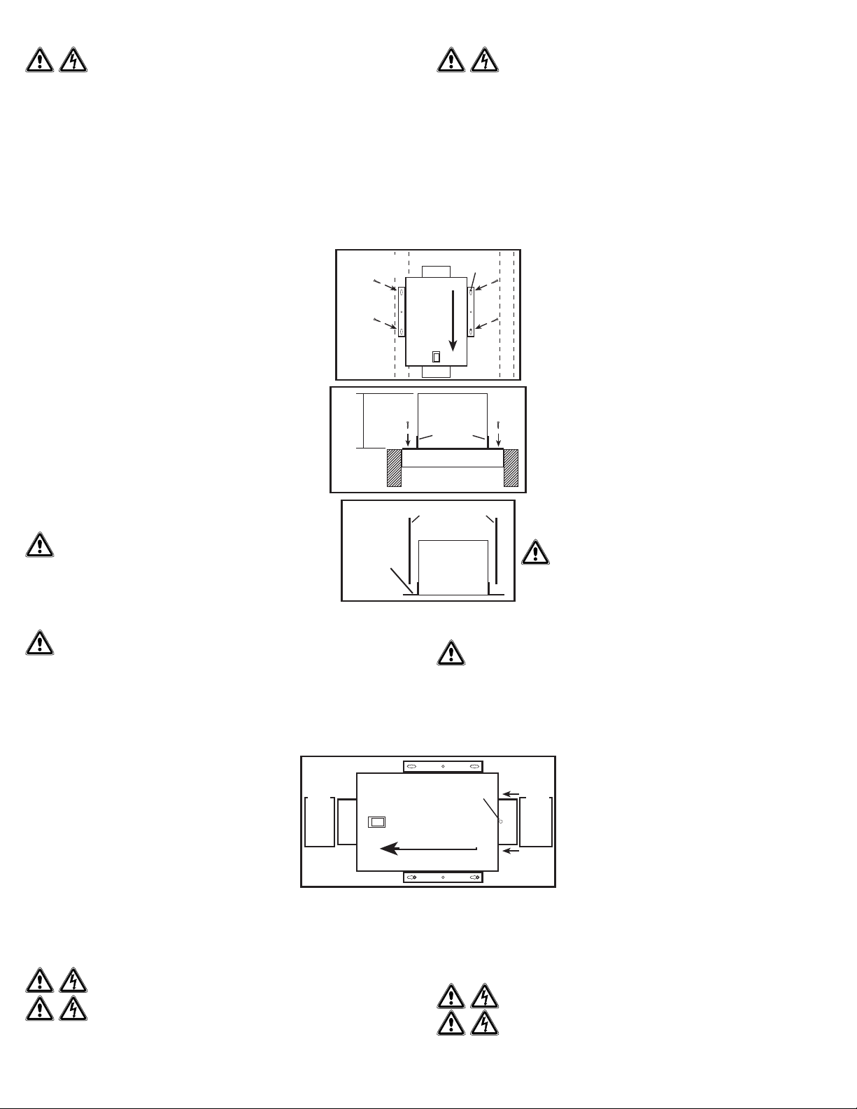
1. Confirm the fan is positioned so the air flow is in the correct direction.
2a. Surface Mounting: Locate at least one stud or joist. Place the fan in
position so that the mounting bracket is centered on the stud or joist
and make the location for the four (4) holes. Remove the fan and install
properly rated wall/ceiling anchors for the holes that do not go directly
into a joist or stud. Position fan in place and secure with screws (not
included) (Figure 1).
2b. Mounting to a Joist: Install two - 2 x 4 headers (not included) between
the joists. Position the fan housing on top of the headers and secure the
mounting brackets with screws (not included) to the header (Figure 2).
2c. Hanging Bar Mounting: Lift unit up onto the threaded rods and
secure in place using appropriate hardware (not included) (Figure 3).
SECTION 3
Ducting
NOTE: 6" OR LARGER RIGID DUCT IS RECOMMENDED FOR BEST
PERFORMANCE.
CAUTION: ALL DUCTING MUST COMPLY WITH LOCAL
AND NATIONAL BUILDING CODES.
NOTE: The ducting from this fan to the outside of the building has a strong effect
on the air flow, noise and energy use of the fan. Use the shortest, straightest duct
routing possible for best performance, and avoid installing the fan with smaller
ducts than recommended. Insulation around the ducts can reduce energy loss
and inhibit mold growth. Fans installed with existing ducts may not achieve their rated air flow.
WARNING: MAKE SURE THE FRESH AIR INTAKE PORT COMPLIES WITH ALL
LOCAL AND NATIONAL CODES AND IS LOCATED AT LEAST 6 FEET AWAY FROM SOURCES
OF CONTAMINATION SUCH AS BUT NOT LIMITED TO: DRYER, FURNACE OR CENTRAL VACUUM
EXHAUSTS, GAS APPLIANCES SUCH AS BBQ GRILLS, GARBAGE BINS OR OTHER EXHAUST PORTS.
NOTE: To ensure quiet operation of in-line and remote fans, each fan shall be installed using
sound attenuation techniques appropriate for the installation. For bathroom and general ventilation
applications, at least 8 feet of insulated flexible duct shall be installed between the exhaust or supply
grille(s) and the fan.
1. Connect the ducting to the fan’s duct collar (Figure 4). Seal
ducting to housing with appropriately rated tape. Use screws
or suitable clamps to secure in place. Make sure the fresh air
intake is connected to a properly installed intake port that is a
suitable weather hood with insect screen to protect air intake. It
is recommended that low restriction termination fittings be used.
2. Ensure duct joints and exterior penetrations are sealed with
caulk or other similar material to create an air-tight path to
minimize building heat loss or gain and to reduce the potential
for condensation. Place/wrap insulation around duct and/or fan
in order to minimize possible condensation buildup within the
duct, as well as building heat loss or gain.
NOTE: At the base of the duct adapter, there is a small diameter test port hole covered with a plastic
cap. Make sure the test port is not covered up with the ducting so that it can be accessed for pitot
tube testing. To access the port, remove the port cover and insert tube.
SECTION 4
Wiring
CAUTION: MAKE SURE POWER IS SWITCHED OFF AT SERVICE PANEL
BEFORE STARTING INSTALLATION.
CAUTION: ALL ELECTRICAL CONNECTIONS MUST BE MADE IN
ACCORDANCE WITH LOCAL CODES, ORDINANCES, OR NATIONAL ELECTRICAL
CODE. IF YOU ARE UNFAMILIAR WITH METHODS OF INSTALLING ELECTRICAL WIRING, SECURE
THE SERVICES OF A QUALIFIED ELECTRICIAN.
www.airkinglimited.com
6728111 Rev. B 12-20 2 of 4
Joist
Solive 2 x 4 Header
2 x 4 embases
Figure 2
Bracket
Support
12"
12 po
Figure 1
Screws
Vis
Stud/Joist
Montant / Solive Anchor / Ancre
Air Flow
Flux d’air
Figure 4
Air Flow / Flux d’air
Intake Ducting
Conduit d’admission
Outlet Ducting
Conduit de sortie
Test Port / Port d’essai
Bracket
Support
Figure 3
Housing / Châssis
Threaded Rod
Tige filetée
INSTRUCTIONS D’INSTALLATION
ATTENTION: VOUS ASSURER QUE L’ALIMENTATION EST COUPÉE
AU PANNEAU DE SERVICE AVANT DE COMMENCER L’INSTALLATION.
SECTION 1
Préparation du Ventilateur
1. Sortir le ventilateur de sa boite et confirmer que toutes les pièces sont présentes. En plus du
ventilateur vous devriez avoir :
2 - Assemblage de collier (attaché) 1 - Feuillet d’instructions / sécurité
2 - Traverses de Montage (attaché)
2. Choisir un emplacement pour votre ventilateur. Pour garantir la meilleure qualité d’air et
performance acoustique, il est recommandé que la longueur de la canalisation et le nombre de
coudes soient réduits au minimum, que le rayon de chaque coude soit aussi grand que possible
pour l’installation, et que des conduits rigides isolés soient utilisés. Ce ventilateur nécessitera
au moins 12 po de dégagement dans le plafond ou le mur. Le ventilateur se monte à l’aide des
supports de montage fournis ou peut être monté en surface sur un mur ou un plafond.
REMARQUE:Le ventilateur doit être installé dans un endroit facilement accessible une fois installé.
3. Aucun matériel amortissant de vibrations supplémentaire n’est nécessaire pour
ce ventilateur.
SECTION 2
Monter le ventilateur
1. Vérifiez que le ventilateur est positionné de manière à ce que le flux d’air
soit dans la bonne direction.
2a. Montage en surface: Localisez au moins un goujon ou une solive. Placez
le ventilateur en position de sorte que le support de montage soit centré sur
le goujon ou la solive et marquez l’emplacement des quatre (4) trous. Retirez
le ventilateur et installez des ancrages muraux / de plafond correctement
dimensionnés pour les trous qui ne vont pas directement dans une solive ou
le goujon. Positionnez le ventilateur en place et fixez-le avec des vis (non
incluses) (Figure 1).
2b. Montage sur une solive: Installez deux - 2 x 4 embases (non incluses)
entre les solives. Positionnez le boîtier du ventilateur sur les embases et fixez
les supports de montage à l’aide des vis (non fournies) (Figure 2).
2c. Montage de la barre de suspension:: soulevez l’unité sur les tiges filetées
et fixez-la en place à l’aide de matériel approprié (non fourni) (Figure 3).
SECTION 3
Conduit
NOTE: UN CONDUIT PLUS RIGIDE DE 6 PO OU PLUS EST RECOMMANDE
POUR UNE MEILLEURE PERFORMANCE.
ATTENTION: TOUS LES CONDUITS DOIVENT ÊTRE
CONFORMES AVEC LES CODES DU BATIMENT LOCAUX ET NATIONAUX.
REMARQUE: La canalisation de ce ventilateur à l’extérieur du bâtiment a un effet
important sur le flux d’air, le bruit et la consommation d’énergie du ventilateur. Utilisez
la route de canalisation la plus courte et la plus droite possible pour une meilleure
performance, et évitez d’installer le ventilateur avec des conduits plus petits que recommandé. L’isolation
autour des conduits peut réduire la perte d’énergie et empêcher le développement de moisissures. Il se peut
que les ventilateurs installés avec des conduits existants n’atteignent pas leur débit d’air nominal.
AVERTISSEMENT: ASSUREZ-VOUS QUE LE PORT D’ADMISSION
D’AIR FRAIS EST CONFORME À TOUS LES CODES LOCAUX ET NATIONAUX ET SE TROUVE
À AU MOINS 6 PIEDS DES SOURCES DE CONTAMINATION TELLES QUE: SÉCHEUSE, FOUR OU
ASPIRATEUR CENTRAL, APPAREILS À GAZ TELS QUE BARBECUE, BACS À DÉCHETS OU D’AUTRES
PORTS D’ÉCHAPPEMENT.
REMARQUE: Pour assurer un fonctionnement silencieux des ventilateurs en ligne et à distance, chaque
ventilateur doit être installé en utilisant les techniques d’atténuation sonore appropriées à l’installation.
Pour les applications de salle de bains et de ventilation générale, un conduit flexible isolé d’au moins 8
pieds doit être installé entre la (les) grille (s) d’évacuation d’air et le ventilateur.
1. Raccordez les conduits au collet du conduit du ventilateur
(Figure 4). Scellez les conduits dans le boîtier à l’aide d’un ruban
approprié. Utilisez des vis ou des pinces appropriées pour les fixer
en place. Assurez-vous que l’entrée d’air frais est raccordée à un
orifice d’admission correctement installé, qui est une hotte contre les
intempéries avec un écran anti-insectes pour protéger l’entrée d’air. Il
est recommandé d’utiliser des raccords d’extrémité à faible restriction.
2. Assurez-vous que les joints des conduits et les pénétrations
extérieures sont scellés avec du mastic ou tout autre matériau similaire
pour créer un passage d’air étanche afin de minimiser la perte ou le gain
de chaleur et réduire le risque de condensation. Placez / enveloppez
l’isolant autour du conduit et / ou ventilateur afin de minimiser la
possibilité d’accumulation de condensation à l’intérieur du conduit, ainsi que la perte ou le gain de chaleur.
REMARQUE: À la base de l’adaptateur de conduit, il y a un orifice de port d’essai de petit diamètre
recouvert d’un capuchon en plastique. Assurez-vous que le port d’essai n’est pas recouvert par la
canalisation, de sorte qu’il soit accessible pour tester le tube de pitot. Pour accéder au port, retirez le
couvercle du port et insérez le tube.
SECTION 4
Câblage ATTENTION: VOUS ASSURER QUE L’ALIMENTATION EST COUPÉE
AU PANNEAU DE SERVICE AVANT DE COMMENCER L’INSTALLATION.
ATTENTION: TOUTES LES CONNEXIONS DOIVENT ÊTRE FAITES EN
CONFORMITÉ AVEC LES CODES ÉLECTRIQUES LOCAUX OU NATIONAUX. SI VOUS
N’ÊTES PAS FAMILIER AVEC LES MÉTHODES D’INSTALLATION DE CÂBLAGE
ÉLECTRIQUE, RECOURREZ AUX SERVICES D’UN ÉLECTRICIEN QUALIFIÉ.
NOTE: This unit includes a side access panel for wiring that does not require
the removal of the fan’s blower assembly.
1. Remove the wire compartment cover screw and place cover in a
secure place (Figure 5).
2. Pull the loose black, white and green wires out from the wire
compartment (additional wires will be present). Install an approved
electrical connector to the wire compartment cover (not included). Run
a black (hot), white (neutral), and a green or bare ground wire from
the supply through the electrical connector. Connect all wires from the
supply to their corresponding wires within the wire compartment
(Figure 6). Use approved methods for all connections.
3. Carefully tuck wires back inside wire compartment and
replace wire compartment cover securing with the screw that
was removed earlier.
SECTION 5
Setting the Speed
1. Determine the CFM required. The unit can be set for 50 CFM
or 80 CFM. Remove the screw securing the access panel cover
in place and open the cover to gain access. Locate the speed
control panel inside the unit (Figure 7).
2. Locate the rocker switch at the top of the wiring compartment
and set to the desired CFM - “Low” for 50 CFM or “HIGH” for 80
CFM (Figure 8).
SECTION 6
Optional Air Filter
An air filter (available separately) can be added to this unit to provide
additional filtration of the intake air. The unit will accept a 9” x 8” x 2” filter.
To install:
NOTE: Adding an air filter will decrease the airflow of the unit. You will
need to increase the CFM selected in SECTION 5 to account for the
decreased air flow. Filters must be changed regularly. Refer to the filter
manufacturer’s recommendations to determine how often the filter should
be changed.
1. Remove the screw securing the access panel cover in place and
open the cover to gain access to the controls and filter area.
2. Ensure the filter is facing the correct way and slide the filter into
the slot in the housing. Make sure the filter is seated all the way to the bottom of the housing
(Figure 9).
3. Close the access panel and reinstall the screw holding the access panel in place.
SECTION 7
Completing the Installation
NOTE: When fan is mounted inline and no penetration is made into
unconditioned spaces, there is no need to use a sealant appropriate
for contact with the building materials present and for the temperature
requirements of the installation to prevent air leakage from
unconditioned spaces. Additional material (backing rod, ceiling material)
are also not required.
NOTE: This unit is equipped with a wire mesh insect screen. Confirm that
the screen is installed on the inside of the unit on the inlet ducting side.
1. If the screen is not in place, insert the screen into the tab at the
base of the unit (make sure the wider side of the screen is running
side to side inside the unit) (Figure 10).
2. Slide the screen to the side with the larger top tab making sure
the screen fits behind the tab (Figure 10).
3. Slide the screen back over towards the smaller top tab making
sure the screen fits behind the tab (Figure 11).
4. Confirm that the screen is being held in place by both top tabs
(Figure 11).
5. Close the access panel and reinstall the screw holding the access
panel in place.
6. Restore power and test your installation.
SECTION 8
Use and Care
CAUTION: MAKE SURE POWER IS SWITCHED OFF AT SERVICE PANEL
BEFORE SERVICING THE UNIT.
1. Cleaning the Fan Assembly: Wipe all parts with a dry cloth or gently vacuum the fan. NEVER
IMMERSE ELECTRICAL PARTS IN WATER.
2. Optional Air Filter: If an optional air filter is installed, it should be checked every month and
replaced at least once every 3 months. Reverse the instructions in the SECTION 6 of these
instructions to remove filter.
NOTE: If you notice a large amount of insects and debris in the air filter, this could be a sign that the intake
weather hood (roof cap or wall cap) might be compromised and need repair or replacing.
Figure 5
Screw / Vis
Wire
Compartment
Cover
Couvercle du
Compartiment
de Câblage
Ground
Screw
Vis au sol
www.airkinglimited.com
6728111 Rev. B 12-20 3 of 4
Figure 10
Base Tab
Languette base
Screen / Grillage
Larger
Top Tab
Grande
languette
supérieure
Rocke
Switch
Interrupteur
à bascule
50 80
Figure 8
Screw
Vis
Figure 7
Figure 9
Filter / Filtre
Screw / Vis
Air Flow / Flux d’air
Figure 6
Supply from house
Alimentation provenant
de la résidence
Neutral (White)
Neutre (Blanc)
Ground (Green or Bare)
Mise à la terre (vert ou nu)
Fan / Ventilateur
Green / Vert
Black / Noir
By others / Par d’autres
Neutral (White)
Neutre (Blanc)
Black / Noir
Figure 11
Smaller Top Tab / Petite languette supérieure
Screen / Grillage Screen / Grillage
REMARQUE: Cette unité possède un panneau d’accès latéral pour le
câblage qui ne requiert pas l’enlèvement de l’assemblage de la soufflante
du ventilateur.
1. Enlever la vis du couvercle du compartiment à câblage et mettre ce
couvercle dans un endroit fiable (Figure 5).
2. Retirez les fils noirs, blancs et verts détachés du compartiment des
câbles (des fils supplémentaires seront présents). Installez un connecteur
électrique approuvé sur le couvercle du compartiment des câbles (non
inclus). Faites passer un fil noir (chaud), blanc (neutre) et un fil de terre
vert ou nu de l’alimentation à travers le connecteur électrique.
Connectez tous les fils de l’alimentation à leurs fils correspondants
dans le compartiment des fils (Figure 6). Utiliser des méthodes
approuvées pour toutes les connexions.
3. Regrouper soigneusement les fils à l’intérieur du compartiment pour
le raccordement et replacer le couvercle du compartiment en le fixant
avec la vis qui fut enlevée précédemment.
SECTION 5
Réglage de la vitesse
1. Déterminez le PCM requis. L’unité peut être réglée sur 50 PCM ou
80 PCM. Retirez la vis qui retient le couvercle du panneau d’accès et
ouvrez le couvercle pour y accéder. Localisez le panneau de contrôle
de vitesse à l’intérieur de l’unité (Figure 7).
2. Localisez l’interrupteur à bascule en haut du compartiment de
câblage et réglez-le sur le nombre de PCM souhaité - « Bas » pour 50
PCM ou « Haut » pour 80 PCM (Figure 8).
SECTION 6
Filtre à air optionnel
Un filtre à air (disponible séparément) peut être ajouté à cette unité pour
fournir une filtration supplémentaire de l’air d’admission. L’unité acceptera
un filtre de 9 po x 8 po x 2 po. Pour installer:
REMARQUE: L’ajout d’un filtre à air diminue le débit d’air de l’appareil.
Vous devrez augmenter le CFM sélectionné dans la SECTION 5 pour
tenir compte du débit d’air diminué. Les filtres doivent être changés
régulièrement. Reportez-vous aux recommandations du fabricant du filtre
pour déterminer la fréquence à laquelle le filtre doit être changé.
1. Retirez la vis qui retient le couvercle du panneau d’accès et ouvrez le
couvercle pour accéder aux commandes et à la zone du filtre.
2. Assurez-vous que le filtre est orienté dans le bon sens et faites glisser le filtre dans la fente du
boîtier. Assurez-vous que le filtre est bien en place jusqu’au fond du boîtier (Figure 9).
3. Fermez le panneau d’accès et réinstallez la vis qui maintient le panneau d’accès en place.
SECTION 7
Complétion de l’installation
REMARQUE: Lorsque le ventilateur est monté en ligne et qu’aucune
pénétration n’est faite dans des espaces non conditionnés, il n’est pas
nécessaire d’utiliser un scellant approprié pour le contact avec les
matériaux de construction présents et pour les exigences de température
de l’installation. Des matériaux supplémentaires (tige de support,
matériau de plafond) ne sont pas non plus nécessaires.
NOTE: Cette unité est équipée d’un grillage pour moustiquaire. Assurez-
vous que le grillage est installé à l’intérieur de l’unité, du côté des conduits
d’entrée.
1. Si le grillage n’est pas en place, insérez le grillage dans la languette
située à la base de l’unité (assurez-vous que le côté le plus large du
grillage est latéral à l’intérieur de l’unité) (Figure 10).
2. Faites glisser le grillage sur le côté avec la plus grande languette
supérieure en vous assurant que le grillage s’adapte derrière la
languette (Figure 10).
3. Faites glisser le grillage vers la plus petite languette supérieure en
vous assurant que le grillage se place derrière la languette (Figure 11).
4. Confirmez que le grillage est maintenu en place par les deux
languettes supérieures (Figure 11).
5 Fermez le panneau d’accès et réinstallez la vis qui maintient le
panneau d’accès en place.
6. Restaurer l’alimentation et tester votre installation.
SECTION 8
Utilisation et entretien
ATTENTION: VOUS ASSURER QUE L’ALIMENTATION EST COUPÉE
AU PANNEAU DE SERVICE AVANT DE COMMENCER L’INSTALLATION.
1. Nettoyage de l’assemblage du ventilateur : Nettoyer toutes les parties à l’aide d’un chiffon
sec ou passer délicatement l’aspirateur sur le ventilateur. NE JAMAIS IMMERGER LES PARTIES
ÉLECTRIQUES DANS L’EAU.
2. Filtre à air optionnel : Si un filtre à air optionnel est installé, il doit être vérifié tous les mois et
remplacé au moins une fois tous les 3 mois. Inversez les instructions de la SECTION 6 de ces
instructions pour retirer le filtre.
REMARQUE: Si vous remarquez une grande quantité d’insectes et de débris dans le filtre à air, cela
pourrait indiquer que la hotte d’aspiration (capuchon de toit ou capuchon mural) pourrait être compromise
et nécessiter une réparation ou un remplacement.
www.airkinglimited.com
6728111 Rev. B 12-20 4 of 4
3
1
1
4
2
6
7
# Qty.
Qte.
Description Replacement Part #
# de pièce remplacement
1 2 Mounting Brackets / Support de montage 5S1650001
2 1 6" Metal Collar (Intake)
Assemblée de collier en métal de 6 po (d’admission)
5S1650030
3 1 6" Metal Collar (Outlet)
Assemblée de collier en métal de 6 po (sortie)
5S1650029
4 1 Blower Assembly / Assemblée de la Soufflante 5S1650031
5 1 Wire Compartment Assembly
Assemblée du compartiment du fil
5S1650032
6 1 Insect Screen / Moustiquaire 5S1650028
7 1 Access Panel / Panneau d’accès 5S1650042
5
LIMITED WARRANTY
WHAT THIS WARRANTY COVERS: This product is warranted against defects in workmanship and/or materials.
HOW LONG THIS WARRANTY LASTS: This warranty extends only to the original purchaser of the product
and lasts for three (3) years from the date of original purchase or until the original purchaser of the product
sells or transfers the product, whichever first occurs.
WHAT AIR KING WILL DO: During the warranty period, Air King will, at its sole option, repair or replace any
part or parts that prove to be defective or replace the whole product with the same or comparable model.
WHAT THIS WARRANTY DOES NOT COVER: This warranty does not apply if the product was damaged or failed
because of accident, improper handling or operation, shipping damage, abuse, misuse, unauthorized repairs
made or attempted. This warranty does not cover shipping costs for the return of products to Air King for repair or
replacement. Air King will pay return shipping charges from Air King following warranty repairs or replacement
ANY AND ALL WARRANTIES, EXPRESSED OR IMPLIED (INCLUDING, WITHOUT LIMITATION, ANY IMPLIED
WARRANTY OF MERCHANTABILITY), LAST ONE YEAR FROM THE DATE OF ORIGINAL PURCHASE OR
UNTIL THE ORIGINAL PURCHASER OF THE PRODUCT SELLS OR TRANSFERS THE PRODUCT, WHICHEVER
FIRST OCCURS AND IN NO EVENT SHALL AIR KING’S LIABILITY UNDER ANY EXPRESS OR IMPLIED
WARRANTY INCLUDE (I) INCIDENTAL OR CONSEQUENTIAL DAMAGES FROM ANY CAUSE WHATSOEVER,
OR (II) REPLACMENT OR REPAIR OF ANY HOUSE FUSES, CIRCUIT BREAKERS OR RECEPTACLES.
NOTWITHSTANDING ANYTHING TO THE CONTRARY, IN NO EVENT SHALL AIR KING’S LIABILITY UNDER
ANY EXPRESS OR IMPLIED WARRANTY EXCEED THE PURCHASE PRICE OF THE PRODUCT AND ANY
SUCH LIABILITY SHALL TERMINATE UPON THE EXPIRATION OF THE WARRANTY PERIOD.
Some states and provinces do not allow limitations on how long an implied warranty lasts, or the exclusion
or limitation of incidental or consequential damages, so these exclusions or limitations may not apply to you.
This warranty gives you specific legal rights. You may also have other rights which vary from state to state
and province to province. Proof of purchase is required before a warranty claim will be accepted.
CUSTOMER SERVICE:
Toll-Free (800) 465-7300
Our Customer Service team is available to assist you with product questions, service center locations, and
replacement parts. They can be reached Monday through Friday, 8am-4pm Eastern. Please have your model
number available, as well as the type and style (located on the label inside of your product).
Please do not return product to place of purchase.
PARTS FOR DISCONTINUED, OBSOLETE AND CERTAIN OTHER PRODUCTS MAY NOT BE AVAILABLE. DUE
TO SAFETY REASONS, MANY ELECTRONIC COMPONENTS AND MOST HEATER COMPONENTS ARE NOT
AVAILABLE TO CONSUMERS FOR INSTALLATION OR REPLACEMENT.
Troubleshooting Guide
GARANTIE LIMITÉE
CE QUE COUVRE CETTE GARANTIE : Ce produit est garanti contre tout vice de fabrication ou de matière.
COMBIEN DE TEMPS CETTE GARANTIE DURE : Cette garantie se rapporte seulement à l’acheteur original
du produit et dure pendant trois (3) années de la date de l’achat original ou jusqu’à ce que l’acheteur original
du produit vend ou transfère le produit, celui qui se produit en premier.
QUE FERA AIR KING : Au cours de la période de garantie, Air King, à son choix, réparera ou remplacera
n’importe quelle partie ou pièces qui s’avèrent défectueuses ou remplacera le produit entier par le même
modèle ou un modèle comparable.
CE QUE CETTE GARANTIE NE COUVRE PAS : Cette garantie ne s’applique pas si le produit était endommagé
ou arrête de fonctionner en raison d’un accident, d’une mauvaise manipulation ou opération, de dommages
d’expédition, d’abus, de mauvaise utilisation, de réparation faite ou tentées non autorisées. Cette garantie ne
couvre pas les coûts d’expédition pour le retour des produits à Air King pour la réparation ou le remplacement. Air
King payera les frais d’expédition de retour de Air King après les réparations ou le remplacement de garantie.
TOUTES LES GARANTIES, EXPRESSES OU TACITES (COMPRENANT, SANS LIMITATION, TOUTE GARANTIE
TACITE DE VALEUR MARCHANDE), DURENT UN AN DE LA DATE DE L’ACHAT ORIGINAL OU JUSQU’À CE
QUE L’ACHETEUR ORIGINAL DU PRODUIT VEND OU TRANSFÈRE LE PRODUIT, CELUI QUI SE PRODUIT EN
PREMIER ET DANS AUCUN CAS AIR KING N’ASSUME AUCUNE RESPONSABILITÉ EXPRESSE OU TACITE
POUR (I) DES DOMMAGES ACCIDENTELS OU INDIRECTS DE N’IMPORTE QUELLE CAUSE, OU (II) LE
REPLACEMENT OU LA RÉPARATION DE TOUS FUSIBLES, DISJONCTEURS OU RÉCEPTACLES DE MAISON.
MALGRÉ N’IMPORTE QUOI À L’EFFET CONTRAIRE, DANS AUCUN CAS LA RESPONSABILITÉ D’AIR KING,
SOUS UNE GARANTIE EXPRESSE OU TACITE, NE DÉPASSERA LE PRIX D’ACHAT DU PRODUIT ET UNE
TELLE RESPONSABILITÉ SE TERMINERA AVEC L’EXPIRATION DE LA PÉRIODE DE GARANTIE.
Certains états et provinces ne permettent pas les limitations de la période de garantie, ou l’exclusion ou la
restriction des dommages accidentels ou indirects, et, par conséquent, les présentes restrictions ne peuvent
pas s’appliquer. La présente garantie vous donne des droits légaux spécifiques et peut-être certains autres
droits qui peuvent varier selon la province. La preuve d’achat est exigée avant qu’une réclamation de
garantie ne soit acceptée.
SERVICE À LA CLIENTÈLE :
Sans frais (800) 465-7300
Notre équipe de service à la clientèle est disponible pour vous aider avec des questions sur le produit, les
adresses des centres de service, et les pièces de rechange. Vous pouvez la rejoindre, du lundi au vendredi,
de 8h:00 à 16h:00 HNE. Veuillez avoir le numéro du modèle disponible, ainsi que le genre et le style (qui se
trouvent sur l’étiquette à l’intérieur de votre produit).
Veuillez ne pas renvoyer le produit à l’endroit de l’achat.
IL SE PEUT QUE LES PIÈCES POUR LES PRODUITS DISCONTINUÉS, OBSOLÈTES ET AUTRES PRODUITS
NE SOIENT PAS DISPONIBLES. POUR DES RAISONS DE SÛRETÉ, BEAUCOUP DE COMPOSANTS
ÉLECTRONIQUES ET LA PLUPART DES COMPOSANTS DES CHAUFFAGES NE SONT PAS À LA
DISPOSITION DES CONSOMMATEURS POUR L’INSTALLATION OU LE REMPLACEMENT.
Guide de dépannage
Trouble Probable Cause Suggested Remedy
1. Fan does not operate when
the switch is on.
1a. A fuse may be blown or a
circuit tripped.
1a. Replace fuse or reset circuit breaker.
1b. Wiring is not connected
properly.
1c. Turn off power to unit. Check that all
wires are connected.
1b. Motor has stopped operating. 1d. Replace motor.
2. Fan is operating, but air
moves slower than normal.
2a. Obstruction in the ducting. 2. Check for any obstructions in the
ducting. The most common are bird
nests in the roof cap or wall cap where
the fan intakes from the outside.
2b. Filter is clogged. 2b. Change air filter (if equipped) or
change/clear bug filter
3. Fan is operating louder
than normal.
3a. Motor is loose. 3a. Turn off power to unit. Remove grill
and check that all screws are fully
tightened. Restore power to unit.
3b. Fan blade is hitting housing of
unit.
3b. Call your dealer for service.
Trouble Cause Possible Solution Suggérée
1. Le ventilateur ne
fonctionne pas lorsque
1a. Un fusible peut être grillé ou
un disjoncteur.
1a. Remplacer le fusible ou réinitialiser le
disjoncteur.
1b. Le câblage n’est pas raccordé
correctement.
1b. Couper l’alimentation de l’unité. Vérifier
que tous les fils sont raccordés.
1c. La moteur est terminee 1c. Remplacez la moteur.
2. Le ventilateur fonctionne,
mais l’air circule plus
lentement que la
normale.
2. Obstruction dans les conduits. 2. Vérifier pour toute obstruction dans les
conduits. Les plus courantes sont des
nids d’oiseau dans le chapeau de toit
ou mural là où le ventilateur entre de
l’extérieur.
2b. Le filtre est bouché. 2b. Changer le filtre à air (si équipé) o
modifier / nettoyer le filtre d’insectes.
3. Le ventilateur fonctionne
de manière plus bruyante
que la normale.
3a. Le moteur est lâche. 3a. Couper l’alimentation à l’unité. Retirer
la grille et vérifier que toutes les vis
sont complètement serrées. Remettre
l’alimentation sur l’unité.
3b. L’hélice du ventilateur frotte
contre le cabinet de l’unité.
3b. Appeler votre marchand pour un service.
Installer / Installateur: Installation Date / Date d’installation:
Place of Purchase / Endroit de l’achat: Model Number / Numéro de modèle:

Other Air King Fan manuals

Air King 5AU42/9215 User manual

Air King

Air King 5AU42/9215 User manual

Air King AK964 User manual

Air King

Air King AK964 User manual

Air King DRLC107 User manual

Air King

Air King DRLC107 User manual

Air King AKLS Series User manual

Air King

Air King AKLS Series User manual

Air King 9320 User manual

Air King

Air King 9320 User manual

Air King 9145 Service manual

Air King

Air King 9145 Service manual

Air King 9146 Service manual

Air King

Air King 9146 Service manual

Air King 9125 User manual

Air King

Air King 9125 User manual

Air King 9224 Service manual

Air King

Air King 9224 Service manual

Air King 4DA35A/9102A Instructions for use

Air King

Air King 4DA35A/9102A Instructions for use

Air King AK80LS User manual

Air King

Air King AK80LS User manual

Air King DRLC107 User manual

Air King

Air King DRLC107 User manual

Air King ASF70 User manual

Air King

Air King ASF70 User manual

Air King 4CH64E/9018E Instructions for use

Air King

Air King 4CH64E/9018E Instructions for use

Air King 9020 Instructions for use

Air King

Air King 9020 Instructions for use

Air King FRAS60 User manual

Air King

Air King FRAS60 User manual

Air King BFQ50 Owner's manual

Air King

Air King BFQ50 Owner's manual

Air King AIF10X User manual

Air King

Air King AIF10X User manual

Air King AK50LS User manual

Air King

Air King AK50LS User manual

Air King 4C523L/9154L Instructions for use

Air King

Air King 4C523L/9154L Instructions for use

Air King ESBGH Series User manual

Air King

Air King ESBGH Series User manual

Air King BFQF50 User manual

Air King

Air King BFQF50 User manual

Air King LEDAK50 User manual

Air King

Air King LEDAK50 User manual

Air King DRLC701 User manual

Air King

Air King DRLC701 User manual

Popular Fan manuals by other brands

Timberk TEF F12 FC3-2 instruction manual

Timberk

Timberk TEF F12 FC3-2 instruction manual

Siku RV 50 C Pro Comfo V2 user manual

Siku

Siku RV 50 C Pro Comfo V2 user manual

Monte Carlo Fan Company Colony 5COM52 Series Owner's guide and installation manual

Monte Carlo Fan Company

Monte Carlo Fan Company Colony 5COM52 Series Owner's guide and installation manual

AERMEC FCX ACB Use and installation  manual

AERMEC

AERMEC FCX ACB Use and installation manual

Uberhaus FTA30-U2 owner's manual

Uberhaus

Uberhaus FTA30-U2 owner's manual

TJERNLUND SS1C SIDESHOT WITH UC1 UNIVERSAL CONTROL (VERSION X.02) 8504103 REV... installation instructions

TJERNLUND

TJERNLUND SS1C SIDESHOT WITH UC1 UNIVERSAL CONTROL (VERSION X.02) 8504103 REV... installation instructions

Craftmade Supreme Air 56 installation guide

Craftmade

Craftmade Supreme Air 56 installation guide

Siku RA1-50 COMFO V2 user manual

Siku

Siku RA1-50 COMFO V2 user manual

475 e2 installation instructions

475

475 e2 installation instructions

Ventis Mk II Filter change guide

Ventis

Ventis Mk II Filter change guide

Emerson HF948BS02 owner's manual

Emerson

Emerson HF948BS02 owner's manual

LUCCI Futura 48 inch manual

LUCCI

LUCCI Futura 48 inch manual

BLAUBERG Ventilatoren TUBO-M Operation manual

BLAUBERG Ventilatoren

BLAUBERG Ventilatoren TUBO-M Operation manual

Lifebreath 195TRV features and benefits

Lifebreath

Lifebreath 195TRV features and benefits

Carrier 42EP Installation, operation and maintenance instructions

Carrier

Carrier 42EP Installation, operation and maintenance instructions

Trox Technik PURELINE35 installation manual

Trox Technik

Trox Technik PURELINE35 installation manual

Bionaire BT14 instruction manual

Bionaire

Bionaire BT14 instruction manual

Casablanca Durant 54103 owner's guide

Casablanca

Casablanca Durant 54103 owner's guide

manuals.online logo
manuals.online logoBrands
  • About & Mission
  • Contact us
  • Privacy Policy
  • Terms and Conditions

Copyright 2025 Manuals.Online. All Rights Reserved.