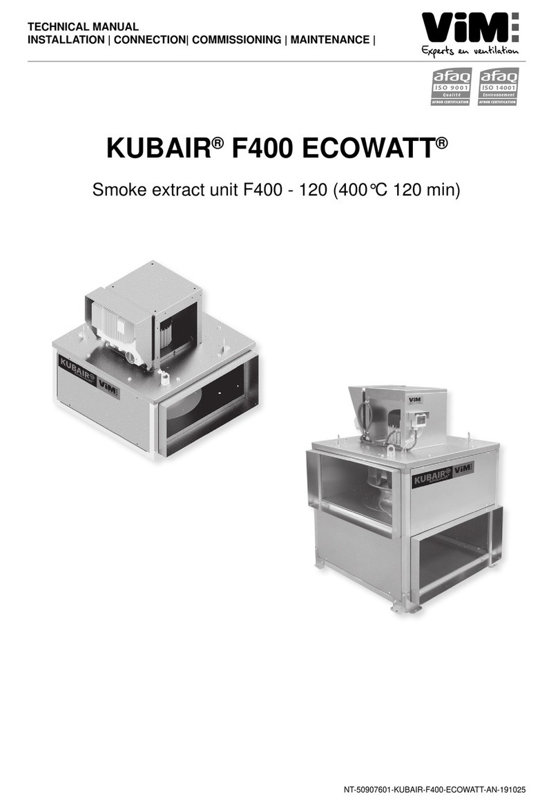
ViM KUBAIR F400 ECOWATT User manual

1/44 NT00000792-KUBAIR-F400-ECOWATT-VENTDRIVE-AN-220314
ENGLISH
TECHNICAL MANUAL
INSTALLATION | CONNECTION| COMMISSIONING | MAINTENANCE |
AFNOR CERTIFICATION
ISO 14001
Environnement
AFNOR CERTIFICATION
ISO 9001
Qualité
KUBAIR F400 ECOWATT®
Smoke extract unit F400 - 120 (400°C 120 min)
VENTIDRIVE controllers

2/44 NT00000792-KUBAIR-F400-ECOWATT-VENTDRIVE-AN-220314
SUMMARY
1. GENERAL........................................................................................................................................... 3
1.1 Disclaimers............................................................................................................................... 3
1.2 Safety instructions.................................................................................................................... 3
1.3 Acceptance – Storage.............................................................................................................. 3
1.4 Warranty................................................................................................................................... 4
2. PRODUCT PRESENTATION.............................................................................................................. 4
3. INSTALLATION .................................................................................................................................. 5
3.1 Dimensions and weight ............................................................................................................ 5
3.2 Summary charts of assembly and accessories........................................................................ 6
3.3 Accessories (dimensions in mm).............................................................................................. 9
3.4 Handling ................................................................................................................................. 13
3.5 Casing assembly.................................................................................................................... 13
4. ELECTRICAL CONNECTION.......................................................................................................... 14
4.1 Preliminary precautions.......................................................................................................... 14
4.2 Electrical characteristics......................................................................................................... 15
4.3 Wiring of INTZ safety switch................................................................................................... 15
5. COMMISSIONING AND CONFIGURATION OF CONTROLLERS.................................................. 17
5.1 Presentation of the VENTIDRIVE controller........................................................................... 17
5.2 Modbus connection - Connection to a BMS........................................................................... 19
5.3 Supported Modbus commands............................................................................................... 20
5.4 Relay operation ...................................................................................................................... 27
5.5 Smoke extraction operation.................................................................................................... 28
5.6 VAVvariableairowmode...................................................................................................... 29
5.7 CAVconstantairowmode .................................................................................................... 38
5.8 COP constant pressure mode................................................................................................ 39
6. MAINTENANCE................................................................................................................................ 41
6.1 Maintenance frequency.......................................................................................................... 41
6.2 Spare parts KUBAIR F400 ECOWATT®................................................................................ 42
7. WASTE MANAGEMENT.................................................................................................................. 42
7.1 Treatment of Packagings and non dangerous wastes ........................................................... 42
7.2 Treatment of a Professional WEEE........................................................................................ 42

3/44 NT00000792-KUBAIR-F400-ECOWATT-VENTDRIVE-AN-220314
1. GENERAL
1.1 Disclaimers
This product has been manufactured according to rigorous technical rules of safety in conformity with EC
standards. The EC declaration may be downloaded from the Internet site (address given on the last page).
Before installing and using this product, carefully read these instructions, which contain important indications
for your safety and the user’s safety during the installation, commissioning and maintenance of this product.
Once the installation is achieved, keep this manual handy nearby the machine for future consultation.
This product must be installed (installation, connections, commissioning, maintenance) and all other inter-
ventions performed by a professional applying recognized good practice procedures, and respecting the
standards and safety regulations in force. The installation must be made in accordance with the prescrip-
tions indicated in the Electromagnetic Compatibility (EMC) and Low Voltage (LV) Directives.
We advise all people exposed to risks to scrupulously respect the accident prevention standards. The ma-
nufacturer may not be held liable for any human injury and/or material damage resulting from the non-res-
pect of the safety instructions or from a change made on the product.
Smoke extract unit KUBAIR F400 ECOWATT®are intended for smoke extraction and ventilation applica-
tions in residential buildings, tertiary buildings, industrial buildings and professional kitchens:
• Outdoor installation
• Environmental temperature range:
-40°C / +50°C.
• Max temperature of extracted air in permanent operation: 120°C
• Relative humidity: min 5% - max 90% non-condensing
• Atmosphere not potentially explosive
• Low salinity atmosphere, with no corrosive chemical agents
1.2 Safety instructions
• Wear suitable PPE (Personal Protective Equipment) before any intervention.
• Before installing the roof fan and its accessories, make sure that the support and the location are
sucientlyresistanttowithstandtheunit’sweightandtheaccessories,ifany.
• Donotremovemeshgrillestoaccesstheimpellerbeforecuttingotheelectricpowersupplywith
the safety switch.
• Iftheworkistobedoneinsidethedevice,cutotheelectricpowersupplywiththemaincircuitbrea-
ker and make sure that nobody can accidentally switch it back on.
• Make sure that moving parts are stopped.
• Make sure that the impeller is not accessible from connection tappings (connection duct or mesh
protection).
Before starting, check the following points:
• Make sure that the device does not contain any foreign body.
• Make sure that all the components are attached to their original locations.
• Check manually that the impeller does not rub or is not blocked.
• Make sure that the mesh protection are in place.
• Make sure that the ground connection is connected.
1.3 Acceptance – Storage
In case of missing items or delivery of non conforming, partially or totally damaged products, the Buyer
shall make, in accordance with article 133-3 of the French Commercial Code, reservations in writing on the
transporterreceiptandconrmthemwithinseventy-two(72)hoursbyregisteredletteralongwithacopy
addressed to the seller. Should the Buyer fail to make reservations when he receives the equipment, he
will not be allowed to make any future claim against us.
The product must be stored protected from the weather, shocks and dirt due to splashings or splatterings
of any kind during transport from the supplier to the end customer, and onto the worksite before installation.
Storage environnement:
Temperature : -40°C to +70°C / Relative humidity : max 95% without condensing.
4/44 NT00000792-KUBAIR-F400-ECOWATT-VENTDRIVE-AN-220314
1.4 Warranty
The equipment is guaranteed for 24 months from the invoice date. The warranty is limited to the replace-
ment of parts or equipment whose operation is recognized as defective by maker, excluding any com-
pensation or penalties. The costs of labor, removal and rest, travel related to the replacement are the
responsibility of the Customer. Excluded from our warranty are defects linked to abnormal use or not in
accordance with the recommendations in our instructions, defects observed as a result of normal wear
and tear, incidents caused by negligence, lack of monitoring or maintenance, defects due to incorrect
installation of devices or poor storage conditions prior to assembly.
In any case, maker is not responsible for transformed material, even partially repaired.
2. PRODUCT PRESENTATION
ECCerticateF400-120N°1812-CPR-0040,accordingtoEuropeanStandardNFEN12101-3
Approved F400 120 (400°C 120 min)
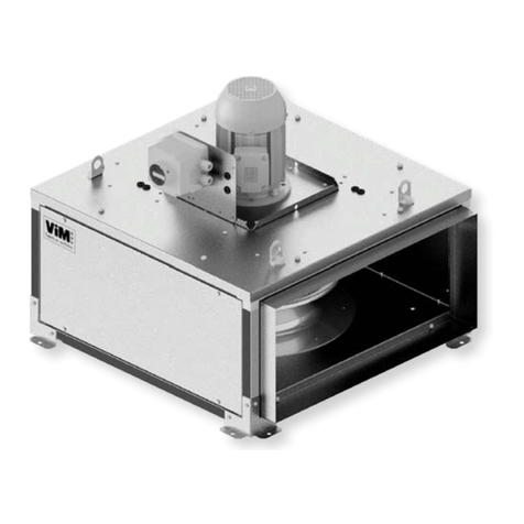
• KUBAIR F400 ECOWATT®CC : complete
unit with multi-directional suction plenum, with
horizontal or vertical axis motor.
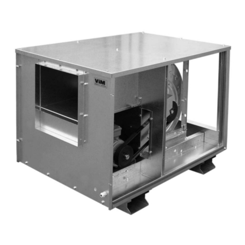
• KUBAIRF400 ECOWATT® MV : single
ventilation unit, with horizontal or vertical axis
motor.
Designation Product code Net weight
Motor electrical characteristics and max. speed
F400 certication and Operating and Maintenance QR
code
Designation Product code Net weight
Motor electrical characteristics and max. speed
F400 certication and Operating and Maintenance QR
code
• 6 sizes : 355 / 400 / 450 / 500 / 630 / 710.
• Airowfrom500to24000m3/h.

5/44 NT00000792-KUBAIR-F400-ECOWATT-VENTDRIVE-AN-220314
Construction
• Detachable galvanised steel sheet panels.
• Modular structure of aluminium sections.
• Connectionby2KUBZ12plainangeswhichareincluded.
• High performance galvanised steel reaction turbine, mounted by direct coupling with the motor.
Motor
• ECOWATT®motor, F class, with remote IP55 controller :
-VENTIDRIVE controller 1 phase power supply 230V 50/60Hz controller input for sizes 355 up to 450.
-VENTIDRIVE controller 3 phases power supply 400V 50/60Hz controller input for sizes 500 up to 710.
• Thermalprotectionttedwithinthecontroller.
Controller supplied as an accessory for KUBAIR F400 ECOWATT®
• ETDZ A: Stand-alone remote touch ModBus control for controlling 1 unit.
• ETDZ R: Network touch remote ModBus control for controlling 2 to 32 units in a network.
Kitchen Option
The kitchen option includes a reinforced seal, a double skin panel (insulation option available) and a drain
to dispose of wash water. The drain should be installed at the bottom of the casing to allow the wash water
tobeeectivelydischarged.
3. INSTALLATION
3.1 Dimensions and weight
KUBAIR F400 ECOWATT
®
MV
Assembly with horizontal motor axis
A
BH
FK
E
JD
C
Tipping risk during
handling operations
Assembly with vertical motor axis(*)
A
BV L
56
A
CG
D
KUBAIR F400 ECOWATT
®
CC
Assembly with horizontal motor axis
A
BH
F
KC
EC
C
JD

6/44 NT00000792-KUBAIR-F400-ECOWATT-VENTDRIVE-AN-220314
KUBAIR F400 ECOWATT
®
MV
Assembly with vertical motor axis(*)
A
BVC
C
GC
56
HC
A
D
C
L
(*)Theunitwithverticalmotoraxismustnotbettedwithmotordown.
Dimensions (mm) Weight (kg)
Size A BH BV BVC C D E EC F G GC H J K KC L MV CC
Naked Insulated Naked Insulated
355 627 695 327 645 263 559 606 790 660 31 50 315 102 826 1103 321 45 48 65 71
400 699 767 361 678 297 631 606 864 732 31 50 349 102 860 1170 321 56 60 79 87
450 779 847 392 738 326 711 606 990 812 31 50 378 102 892 1230 321 73 78 98 108
500 858 925 424 784 338 768 700 1039 890 42 62 402 112 954 1294 351 94 100 121 132
630 10661133 488 912 403 977 700 11831098 42 62 466 112 10181422 351 133 140 177 195
710 11941261 551 1032 462 1104 906 13251226 42 62 526 112 10701533 446 159 168 279 303
3.2 Summary charts of assembly and accessories
KUBAIR F400 ECOWATT
®
CC
KUBZ 01 CC
KUBZ 04 straight
KUBZ 07
KUBZ 16
KUBZ 12
KUBZ 15 CC
KUBZ 04 straight
KUBZ 02
KUBZ 12
MSCZ
MSDZ
KUBZ 08
KUBZ 17

7/44 NT00000792-KUBAIR-F400-ECOWATT-VENTDRIVE-AN-220314
KUBAIR F400 ECOWATT
®
MV
KUBZ 03
KUBZ 12
KUBZ 17
KUBZ 08 KUBZ 01 MV
KUBZ 16
KUBZ 12
KUBZ 15 MV
KUBZ 07
KUBZ 03
The TCDZ accessories on the diagram below can be used with the KUBAIR F400 ECOWATT®MV with
a vertical axis motor: (example below)
KUBZ 08
KUBZ 17
KUBZ 12
KUBZ 11
KUBZ 12
TCDZ 04

8/44 NT00000792-KUBAIR-F400-ECOWATT-VENTDRIVE-AN-220314
KUBAIR F400 ECOWATT
®
MV
with vertical axis motor
TCDZ03
TCDZ03
SIL
TCDZ 04 TCDZ 07 TCDZ 02 TCDZ 09
or or or
Optional accessory according to selection.
TCDZ08

9/44 NT00000792-KUBAIR-F400-ECOWATT-VENTDRIVE-AN-220314
3.3 Accessories (dimensions in mm)
E
Ø F Circular exible sleeve
E
A+3
B+3
Rectangular exible sleeve
AB
B
A
C
Standard support for horizontal axis motor:
Thissupportallowstoxtheunitontotheoorwiththemo-
tor in horizontal axis position. Reposition, on the 2 corners
oftheunitonthesideoppositethemotor,2ofthexingsof
theunitandreplacetheother2xingsontheunitbythose
supplied with the KUBZ01. These 4 xings are screwed
onto the unit with 16 self-drilling screws 4.8x12 supplied.
The2supportarmsmustbexedonthe4unitxingswith
the 4 M8 x 15 screws supplied. The the motor controller
must be removed and then reattached to the motor vertical
sideoftheenginecasing.Thexingholesaredesignedto
berexedwithitsself-drillingscrews.
A
B
Connection ange
Thisconnectingangeisxedtotheplainangewithits4
cornerstoallowthexingofaductwithMETUframework.
A
A
ØF Circular connection to the MV suction, horizontal axis
motor
A+3
B+
3
H
Ø F
A+3
B+3
H
ØF
ØF
A+3
B+3
H
Rigid straight or errant circular connection
ØA
H
S
G
Fz
B
C
d
ØA
H
S
G
Fz
B
C
d
Vibration isolating devices
4 vibration isolating devices supplied with 4 screws to
attach them to the casing.
MSDZ
MSCZ
KUBZ 01
KUBZ 02
KUBZ 03
KUBZ 04
KUBZ 05

10/44 NT00000792-KUBAIR-F400-ECOWATT-VENTDRIVE-AN-220314
AB
C
Capot KUBAIR
The motor cowl is used for external installations. It is
screwed (screws supplied) onto the motor support panel.
DB
A
C
A
B
Rain guard with bird guard
Theseguardsareattachedafterthesuppliedplainange
(KUBZ 12) has been detached from the casing.
C
AA
B
ØD
75 75
EØ12
Double suction plenum
To be bolted under the casing, without any accessory
between the KUBZ 11 and the casing.
A
B
J
Plain ange for spool piece
2 plain anges are supplied already mounted on the air
deliveryandsuction.Otherplainangescanbesupplied
and mounted.
PURGE (OPTION KITCHEN KUBZ 14)
To install the drain in the lower part of the casing, drill a
hole through the 2 sheets. Enlarge the hole with a step
drill up to Ø20. Screw on the plastic drain. Make a silicone
gasketinsidethecasingaroundthedrainange.Tighten
the two skins manually with a spanner, limiting the sheet
metal deformation.
AB
B
A
C
Covering - horizontal axis motor
Assembly of the cover: the cover is attached with 4 (MV
version) or 8 (CC version) 4.8 x 12 self-drilling screws
which are supplied.
A
A ( 1 : 2 ) Over-pressure ap to be mounted on the discharge
side for horizontal shaft motor.
Ensures good water and air tightness when the unit is
stopped.
Supplied with 4 bolts for xing to the unit. Install one
KUBZ16perdischargesideinsteadofthesmoothange
KUBZ 12.
B
B ( 1 : 2 )
Over-pressure ap to be mounted on the discharge
side for vertical shaft motor.
Ensures good water and air tightness when the unit is
stopped.
Supplied with 4 bolts for xing to the unit. Install one
KUBZ17perdischargesideinsteadofthesmoothange
KUBZ 12.
KUBZ 06
KUBZ 08
KUBZ 07
KUBZ 11
KUBZ 12
KUBZ 14
KUBZ 15
KUBZ 16
KUBZ 17

11/44 NT00000792-KUBAIR-F400-ECOWATT-VENTDRIVE-AN-220314
Dimensions (mm) and weight (kg)
MSDZ - MSCZ - KUBZ 02, 08, 12, 16 et 17 Weight
Size A B C D E ØF H J KUBZ
01 KUBZ
03 KUBZ
04 KUBZ
06 KUBZ
07 KUBZ
08
355 559 263 197 194 160 400 670 80 7,0 2,9 7,5 3,6 1,9 2,0
400 631 297 216 213 160 450 670 80 8,2 3,5 8,5 3,6 2,4 2,4
450 711 326 233 234 160 500 670 80 9,7 4,2 9,6 3,6 2,8 2,8
500 768 338 240 249 160 560 670 80 10,6 4,6 10,5 5,4 3,1 3,1
630 977 403 278 305 160 710 670 80 13,8 6,9 13,2 5,4 4,5 4,3
710 1104 462 311 340 160 800 670 80 17,0 8,3 15,1 6,9 5,6 5,3
KUBZ 01 KUBZ 11 KUBZ 15
Size MV CC Size A B C ØD E Weight Size MV CC
A B A B A B A B
355
668 50 848 50
355
622 448 238 355 662 21
355
658 391 658 636
400
668 50 823 50
400
694 498 260 400 734 25
400
731 425 731 721
450
668 50 1048 50
450
774 555 289 450 814 30
450
812 453 812 790
500
762 50 1097 50
500
852 675 349 560 892 37
500
890 485 890 828
630
855 50 1242 50
630
1060 805 441 630 1100 81
630
1098 550 1098 953
710
977 50 1401 50
710
1188 885 481 710 1228 99
710
1226 610 1226 1112
Size KUBZ 05 KUBZ 06
A C H G B d S Screws A B C
355 à 450 60 90 24 M6 76 62 3 M6x16 340 325 305
500 et 630 80 120 27 M8 100 82 3 M8x15 415 475 355
710 100 148 28 M10 124 102 3 M10x15 510 465 450
E
G
S
Sealing frame
Embed the frame into the constructed support and make
surethatthexinglugsareembeddedintotheconcrete.
A mini
70 mm
E
G
M
K
Energy-saving component
Assemble the energy-saving component inside the ups-
tands, under the casing. Make sure that the components
are able to move freely before the casing is assembled.
Provide for a drop in pressure of 50 Pa.
TCDZ 02
TCDZ 03

12/44 NT00000792-KUBAIR-F400-ECOWATT-VENTDRIVE-AN-220314
Straight, inclined and acoustic upstand
According to DTU 43.1, it is possible to attach a TCDZ 03
energy-saving component (excluding TCDZ 09) which is
placed inside the upstand.
For any casing with an acoustic straight upstand (TCDZ
09), provide for a drop in pressure of 80 Pa.
E
G
150
100
100
α
100
G
N
E
R
E
G
N
800
100
200
G
E 200 mm upstand lift
Makes it possible to increase the height of the casing by
200 mm, or to mount a TCDZ 03 energy-saving component
onto a TCDZ 02 sealing frame.
Costière
droite
Plaque
d’adaptation
Volet d’économie
d’énergie
Réhausse
de costière
A
E
E
G
Ø19
Ø12
J
Sound absorber
Provide for a drop in pressure of 80 Pa.
Casing size Accessory size A E G J S
355/400 2 540 450 478 630 30
450/500 3 660 570 598 700 40
630 4 800 668 698 700 40
710 5 930 830 866 700 40
Casing size Accessory size M N K R Ø D T
355/400 2 145 678 400 300/500/700 315/355/400/450* 50/65/80/80
450/500 3 170 798 490 300/500/700 400/450/500/560* 80/80/80/80
630 4 170 898 605 300/500/700 450/500/560/630 80/80/80/90
710 5 190 1066 730 300/500/700 560/630/710 80/90/120
TCDZ 07TCDZ 04
TCDZ 09
TCDZ 08
SILS

13/44 NT00000792-KUBAIR-F400-ECOWATT-VENTDRIVE-AN-220314
Accessory TCDZ 02 TCDZ 03 SILS TCDZ 04 TCDZ 07 (30°) TCDZ 09 TCDZ 08
Size Weight Weight Weight R Weight Weight Weight Weight
355/400 2,5 5,0 23,0 300/500/700 11,0/15,5/20,0 11,2 34,0 6,2
450/500 4,0 6,0 37,0 300/500/700 13,5/19,0/25,0 14,8 51,0 10,5
630 4,5 8,0 45,0 300/500/700 20,5/29,5/38,0 24,2 65,5 12,2
710 6,0 11,0 65,0 300/500/700 25,5/37,0/48,0 32,4 90,5 15,0
3.4 Handling
To keep people safe or prevent damage to property,
use compliant handling equipment that is in a good
condition.
The casing must be lifted at the 4 lifting lugs.
Use slings with a length that is at least double the
height of the casing. Make sure that the slings do
not rub against the motor cowl or the electrical
accessories.
If in doubt, detach it to avoid any damage.
3.5 Casing assembly
Thesupportsurfacethatwillsupportthebaseofthecasingmustbeasataspossible(sealingframeor
upstand supplied on demand). A seal of foam or similar material (not supplied) is recommended between
the support surface and the base of the casing. A maximum incline of 2.5° is tolerated between the motor
axis and the vertical axis (see diagram below).
Let available space for maintenance operations (§ "6. MAINTENANCE", page 41).
2,5°
Make sure that the support is adapted to the weight
of the whole machine and its various accessories.
Attach the casing at the Ø20 holes provided for this
purpose. You are advised to use a LL washer. Any
screws that are not properly tightened may make
noises and cause harmful vibrations. Once the ma-
chine has been correctly set up, make sure that the
motor turbine is able to rotate freely without any fric-
tion or noise. Vibration isolating devices are avai-
lable: KUBZ 05.

14/44 NT00000792-KUBAIR-F400-ECOWATT-VENTDRIVE-AN-220314
Detaching and re-assembling casing panels
The smooth side panels are easy to detach by
loosening their screws. They are repositioned in the
same way.
4. ELECTRICAL CONNECTION
4.1 Preliminary precautions
Give the user the operating instructions for the unit and the installed accessories so that they can be
consulted at any time.
Connection
Electricalconnectionsmustbemadebyqualiedpersonnel.Caution:beforealloperations,checktheab-
sence of voltage. The electrical connection will be made according to the NF C15-100 standard indicating
that the motor must be protected by an omnipolar device having an opening distance of 3 mm per contact.
Do not forget to connect the earth. The power supply of the unit must have short-circuit protection.
Use in smoke extraction
Refer to standard NF S 61-932 for connection and installation. Use high temperature cable type CR1-C1.
The cable must be protected against UV radiation.
Electrical cables and accessories must be dimensioned in accordance with article 433-3. of standard NF C
15-100: "the cross-section of the conductors of the line is determined by a current admissible equal to 1.5
times the nominal motor current". No thermal protection device is required. If the smoke extraction system
is not installed in the smoke extraction circuit, only magnetic protection must be used.
In addition, it is mandatory to protect the cables from mechanical aggression during the routing of the
smoke extraction circuit to the proximity switch on the unit.
In comfort use, the motor is protected by a thermal protection device provided by the controller.
ECM power supply
This electronically commutated motor cannot be powered directly from the mains, on pain of des-
truction. The power supply must be done by the controller. Starting up the system and stopping
of the device must be done via the Start/Stop inputs of the following controller the wiring chosen
in § "5. COMMISSIONING AND CONFIGURATION OF CONTROLLERS", page 17. Do not stop the
appliance by switching o the power supply of the controller by a supply network failure.
Commissioning
Before starting the turbine, make sure that the motor and impeller assembly rotates freely and that there
isnohasnoobjectlikelytobeprojectedbytheturbine.Theprotectionsmustbexedonthecasingin
ordertoavoidaccidentalcontactwiththerotatingparts.Themachinemustbexedtoitssupportbefore
being power supplied. Switch on the power supply for a brief moment to check the direction of rotation of
the turbine.

15/44 NT00000792-KUBAIR-F400-ECOWATT-VENTDRIVE-AN-220314
The impeller rotating direction must correspond to each speed in the direction indicated by the
arrow on the product. A centrifugal backward fan unit with an impeller that does not rotate in the
right direction still creates a airow and a low pressure in the duct. An incorrect rotating direction
can lead to an abnormal overheating of the motor, resulting in its destruction and cancelling our
manufacturer’s warranty.
Iftherotatingdirectionisincorrect,cutotheelectricalpowersupply,makesurenopowerispresent.
Contact after-sales service. Do not modify wirings, as this might seriously damages the unit.
While running, make sure that the motor’s absorbed current is not more than 10% above the identity plate
indicated current .
Once the roof fan is installed and the tests successfully completed, present the main points of the operation
and maintenance manual to the user, and explain:
• How to start up and shut down.
• How to change the operating modes.
4.2 Electrical characteristics
Model Nom P.
(kW) Nom. C (V) Nom. I. (A)
230V Nom. I. (A)
400V INTZ Electrical protection
necessary
355
0,70 1 ph. 230 V 3,05 INTZ 1V15 10 A
400
0,72 1 ph. 230 V 3,05 INTZ 1V15 10 A
450
1.24 1 ph. 230 V 5,40 INTZ 1V15 10 A
500
1,70 2 ph. 400 V 3,52 INTZ 1V15 16 A
630
3,16 2 ph. 400 V 6,99 INTZ 1V15 16 A
710
5,91 2 ph. 400 V 12,43 INTZ 1V22 16 A
The short-circuit protection equipment must at least have a "C" tripping curve in accordance with IEC
60898-1.
The power supply is compatible with IT neutral regime, controller capacity : 500nF.
4.3 Wiring of INTZ safety switch
Safety switch delivered factory wired and mounted.
Note: the safety switch is sized to be used in smoke extract application for a 400V three-phases or 230V
single-phase 50/60Hz power supply. The switch is used to isolate the unit from the electrical network in
caseofmaintenanceoperations,nottopilottheuniton/o.
Safety switch access
The switch is located next to the controller.
KUBAIR F400 ECOWATT
®
Motor controller
INTZ - Safety switch
VCHV-A-Pressureorairow,in
COP and CAV units
PTHV-A-Airowdisplay,inVAV
unit with display

16/44 NT00000792-KUBAIR-F400-ECOWATT-VENTDRIVE-AN-220314
Wiring of version with INTZ safety switch 1V15
Unit size 355 / 400 / 450
with one-phase controller Unit size 500 / 630
with 3 phases controller
Neutre
Phase
INTZ 15A
Neutral
L1
L2
INTZ 15 A
L3
Wiring of version with INTZ safety switch 1V22
Unit size 710 with 3 phases controller
L1
L2
L3
INTZ 22 A
3

17/44 NT00000792-KUBAIR-F400-ECOWATT-VENTDRIVE-AN-220314
5. COMMISSIONING AND CONFIGURATION OF CONTROLLERS
5.1 Presentation of the VENTIDRIVE controller
The ECM motor controller controls the motor according to an adjustment potentiometer on the controller,
an external 0-10V signal or a setpoint given by GTC ModBus.
5.1.1 Controller terminal block
UVWPEBR- BR+
A
B
Gnd
+10V
0-10V
GND
D2
D1
D0
Gnd
R2 No
R2 C
R2 Nc
R1 No
R1 C
R1 Nc
Gnd
+24V
+10V
AO_1
DI_4
DI_3
AI_2
Therm
Gnd
A
B
C
LNPE
Factory-tted motor terminal block
It is imperative that the U-V-W cable
sequence is observed
Factory-tted terminal block
One-phase
KUBAIR 355
KUBAIR 400
KUBAIR 450
Running status LED
RJ 12 - Modbus connectors
Command terminal block.
The various control functions are dened
in the operating instructions.
A
B
Gnd
+10V
0-10V
GND
D2
D1
D0
Gnd
R1 C
R1 Nc
Gnd
+24V
+10V
AO_1
DI_4
DI_3
AI_2
Therm
Gnd
R2 No
R2 C
R2 Nc
R1 No
Command terminal block
Modbus
Speed control via analogue input 0-10V
VAV versions : factorywired potentiometer
COP and CAV versions:VCHV-A factory wired
Digital input Reset alarm
Digital On/O input (Shunt wired from factory)
Not used
Outlet +24V
Outlet +10V
Total consumption
max 450mA
0-10V outlet, representative of the motor speed
Digital input disabled
Digital input Fire mode (Thermocontact wired from factory)
1
2
3
4
5
6
7
8
9
10
25
24
23
22
21
20
19
18
17
16
15
14
13
12
11
No function
Output 1 relay
Running relay
Output 2 relay
Fault relay
Max 1A at
30VDC and 24VAC
L1 L2 PE
L3
Three-phases
KUBAIR 500
KUBAIR 630
KUBAIR 710
Terminal block accessible
under the blue cover
by means of 6 TX20 screws
Motor connection - Factory-made
Control connection
PE M25 Multipass - 3 passes :
- 2 available in VAV version without display
- 1 available on all other versions
Cable sheath Ø 6.8 to 9 mm
Power connection - Factory-made to INTZ

18/44 NT00000792-KUBAIR-F400-ECOWATT-VENTDRIVE-AN-220314
5.1.2 Alarms and operating status indication
LED indication
An LED is present next to cable glands on the controller.
Constant green LED: the supply voltage is connected.
GreenLEDashing:Modbuscommunicationisactive.
Constant red LED: at least one critical alarm is active.
Flashing red LED: a non-critical alarm is active.
Consultation of alarms and operating status of the extractor by the remote controller ETDZ A
(optional)
The ETDZ A remote control is connected to the Modbus RJ12 "C" connector on the terminal block.
The ETDZ A remote control (touch control) provides accurate information on the type of alarm.
You can view an alarm via ETDZ A, following the instructions below:
Warning & alarms
Setpoint 0%
RESET
ALARM/WARNING DESCRIPTION
Current speed
Drive type
Drive power in
Controle type
_ _ _ RPM
PM
_ _ _ kW
0-110V
Alarm 1001
Motor stop due to alarm
Alarm 1202
One or more lacking phases in
motor connection (U, V, W)
A bell appears at the top left of the
screen, press it to view the alarms.
Alarm board - requires ETDZ remote control
Alarm code Trigger Motor running / action
1101 Input voltage low Voltage too low to operate Reduced performance
1102 input voltage high Voltage too high to operate Motor stops after 5 restarts caused by
the same fault within 60 min.
2301 Temperature high The ambient temperature around the
controller is too high Reduced performance
2101 Input phase warning Phase loss, unbalanced phases Motor stops after 5 restarts caused by
the same fault within 60 min.
2203 Brake choper fault The rotor cannot rotate due to
mechanical locking of the rotor or
impeller Motor stops after 5 restarts caused by
the same fault within 60 min.
1202 Motor phase error One or more phases / One or more
motor cables are disconnected Motor stops after 5 restarts caused by
the same fault within 60 min.
2204 Ext. 24V overload Overload or short circuit in the supply
voltage +24V Reduced performance
Reset alarm via terminal block
After the problem has been solved, you can reset an alarm by closing the contact between DI2 (terminal
7)andGND(terminal6),animpulseissucient(Terminalsseepage17).

19/44 NT00000792-KUBAIR-F400-ECOWATT-VENTDRIVE-AN-220314
5.2 Modbus connection - Connection to a BMS
In the case of a connection to a BMS, the Modbus connection allows, according to unit versions:
• KUBAIR F400 ECOWATT®–VAVvariableairowdriving:
-On / Off,
-Speed adjustment,
-Reading of registers.
• KUBAIR F400 ECOWATT®–AdjustmenttoCAVconstantairoworCOPconstantpressure:
-On / Off,
-Reading of registers.
Recommendation for ModBus connection.
The controller is equipped with four Modbus connectors :
• 3 RJ12 connectors,
• 3 spring terminals, Bus A, Bus B and GND.
A
B
Gnd
1
2
3
C
V+
Add. Pin 1
Bus B
Bus A
V+
Gnd
A
V+
Add. Pin 1
Bus B
Bus A
Add. Pin 2
Gnd
B
Add. Pin 1
Bus B
Bus A
Add. Pin 2
Gnd
The 3 RJ12 connectors are marked "A", "B" and "C".
• "A": Modbus connection, slave, +24V voltage in the connector.
• "B": Modbus connection, slave, no +24V voltage in the connector. For connection to a PC software
with a USB-RS485 adapter - RJ12 connection.
• "C": Modbus connection, master, external equipment (ETDZ A connection, accessory not supplied).
Werecommendusinganunshielded6-coretelecommunicationcable,30AWG/0.066mm²atwithRJ12
connectors at each end, keeping the same wire colour sequence.
Eachcontrollerhasapre-installedModbusterminationresistorofvalue1kΩwhichissucientformost
applications.
An additional Modbus terminating resistor should not be used except for the following installations where
the Modbus exceeds 100 m for an in-line Modbus connection (Daisy Chain - typical industrial architec-
ture). If the Modbus exceeds 100 m, it may be necessary to install an additional termination resistor
worth180Ω.Theresistormustbeinstalledonthelastlinecontroller.ForModbusstarinstallations,a
Modbus terminating resistor is not required.

20/44 NT00000792-KUBAIR-F400-ECOWATT-VENTDRIVE-AN-220314
Communication parameters
In the Holding Registers
0x03 : Read
0x06 : Writing a register
0x10 : Write several registers
Register Address Function Value Resolution / Option Unit Fault value
4x0017 16 Modbus ID 1 to 247 1 - 54
4x0018 17 Modbus
response time 0 to 200 1 ms
4x0020 19 Trial number 1 to 100 1 -
4x0022 21 CommTimeout 0 to 240 1 Sec 10
4x0023 22 CommRate 0 to 4
0 – 9600
1 – 19200
2 – 38400
3 – 1152000
4 - 57600
bps 38400
4x0024 23 Parity 0 to 2 0 – None
1 – Odd
2 - Even - None
4x0025 24 Stop Bits 0 to 2 0 – INVALID
1 – 1
2 - 2 - 1
5.3 Supported Modbus commands
Function code Description
1 Read Coil Status
2 Read Input Status
3 Read Holding Registers
4 Read Input Registers
5 Force Single Coil
6 Preset Single Registers
8Diagnostics.Sub-function00Only-ReturnQueryData(loopback).
15 Force Multiple Coils
16 Preset Multiple Registers
5.3.1 Coil Stat Bits
Les Coil Stat Bits Available Coil Stat Bits are shown in table below.
Standard Modbus (RTU)
Coil Stat Bits: 23 (R/W)
0x01: Read
0x05: Write Single Coil (NOTE: ON => output value = 0xFF00)
0x0F: Write Multiple Coils
Register Address Function Range Active state
0x0001 0 Motor ON/OFF 0 - 1 1 = ON
0x0002 1 Reset Alarms 0 - 1 1 = Reset
0x0004 3 FireMode 0 - 1 1 = Active
0x0006 5 Rotation 0 - 1 1 = CW
0x0007 6 Disable V_Ripple protection 0 - 1 1 = Disable
0x0008 7 Control mode 0 - 1 0 = Modbus, 1 = 0-10V
0x0009 8 Use alternate comm. settings 0 - 1 1 = Alternate
0x0010 9 Autodetect communication 0 - 1 1 = Enable
0x0011 10 Analog start signal 0 - 1 1 = Enable
0x0012 11 Invert analog speed input 0 - 1 1 = Invert
0x0013 12 Allow using Field Weakening 0 - 1 1 = Allow FW
Other manuals for KUBAIR F400 ECOWATT
1
This manual suits for next models
2
Table of contents
Other ViM Fan manuals

ViM
ViM KUBAIR F400 ECOWATT User manual

ViM
ViM TEDH F400 User manual

ViM
ViM KDTA-R F400 User manual

ViM
ViM TEDH F400 User manual

ViM
ViM TEDH F400 User manual

ViM
ViM KUBAIR F400 User manual

ViM
ViM TEDH F400 User manual

ViM
ViM JBRB ECOWATT PR VCHV User manual

ViM
ViM KUBAIR F400 ECOWATT CC User manual

ViM
ViM JBRB ECOWATT PR User manual
Popular Fan manuals by other brands

Lindab
Lindab FORMO PKA installation instructions

Hunter
Hunter Vancouver 21328 Manual de Installatión y Operatión

Titon
Titon Titon Ultimate dMEV product manual

Lütze
Lütze AirBLOWER operating instructions

Lennox
Lennox FLATAIR KFC Series Installation and operating manual

Hyundai
Hyundai H-SF16-RC02 instruction manual