Air Liquide NERTAMATIC 450 AC/DC User manual

NERTAMATIC 450 AC/DC -1
NERTAMATIC 450 AC/DC POWER SOURCE
NO. W000315023
EDITION: EN Instructions for use REF.: 8695-5522
REVISION: D DS:
DATE: 11-2008

1- DESCRIPTION
-2 NERTAMATIC 450 AC/DC

1- DESCRIPTION
NERTAMATIC 450 AC/DC -3
REVISIONS
REVISION B 07/05
DESIGNATION PAGE
Change fuse values 19
REVISION C 06/06
DESIGNATION PAGE
To change logos -
REVISION D 11/08
DESIGNATION PAGE
Complete update + spareparts newoffer -

1- DESCRIPTION
-4 NERTAMATIC 450 AC/DC
1- DESCRIPTION

1- DESCRIPTION
NERTAMATIC 450 AC/DC -5
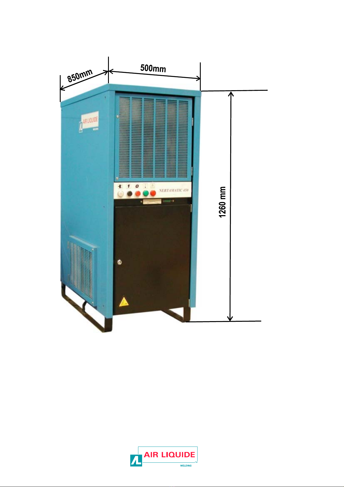
NERTAMATIC 450 is a source for supplying power to TIG or
plasma welding torches from the mains.
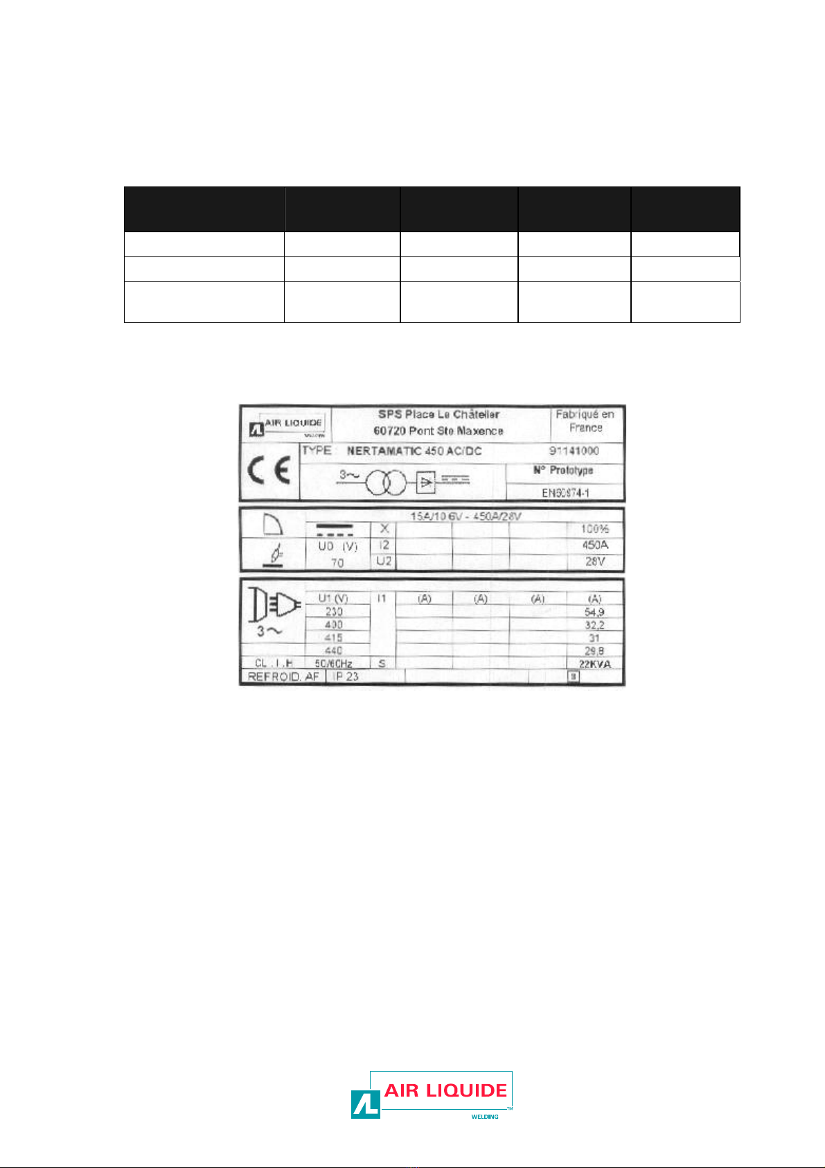
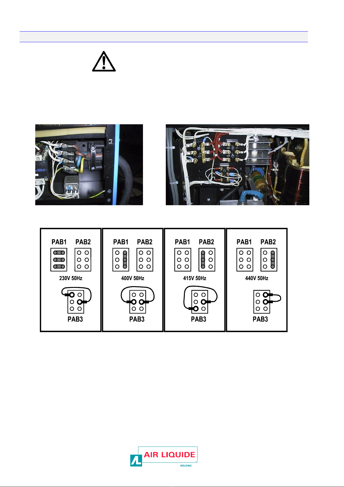
3-phase power
supply + ground 230 V 400 V 415 440 V
Maximum intensity 54.9 A 32.2 A 31 A 29.8 A
Fuse size 60A 40A 40A 40A
Section of the power
supply cable 10mm² / phase 6mm² / phase 6mm² / phase 6mm² / phase
This power source is a power supply where the intensity is imposed at all times. The
system stability relies on an electronic current regulation system that can react at the speed
of the arc.
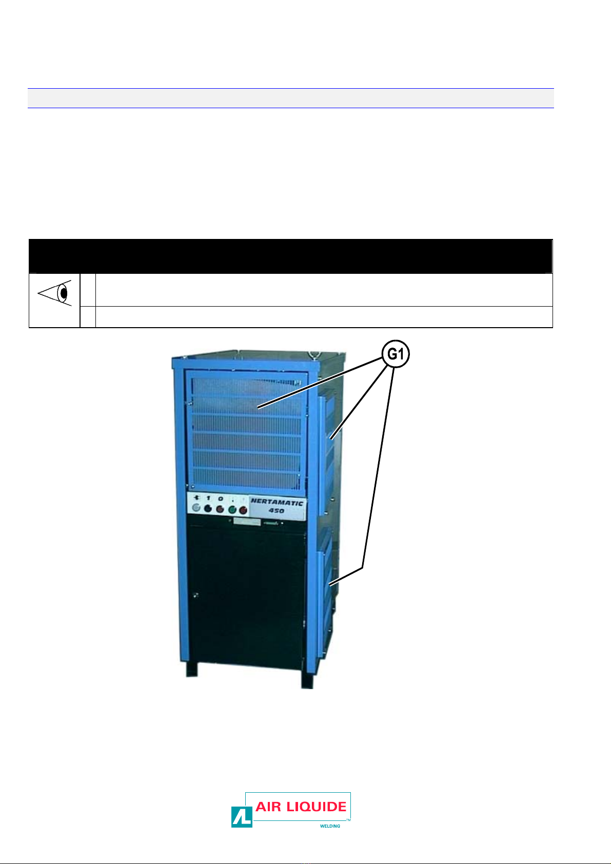
It is cooled by a forced ventilation system. Filters placed on the air inlets extend the life
of the components of the power source when it is used in dusty environments.
The cooling air is taken in through openings in the side panels and the upper front door
and then transferred to the rear by means of a fan.
NERTAMATIC 450 has several auxiliary power supply systems, which are alternative low-
voltage sources that power the cycle box, the AVC, the wire feeding funcion, the BRT, some
movements etc.
It offers an internal visualisation of its operating status and a galvanised insulated interface
for dialogue with the “outside”.

2 – INSTALLATION
-6 NERTAMATIC 450 AC/DC
2 – INSTALLATION
A) UNPACKING - HANDLING
1) Unpacking 2) Handling
Cut the box straps. You can now install the power supply either :
Remove the cover plate and protective cover
(cardboard). - with a fork lift truck or a pallet truck,
Disunite the power supply from the pallet (8 mm
nuts). - or using the 2 slinging rings intended for that
purpose with a crane or a lifting bridge.
Operator's protection:
Helmet - Gloves - Safety
shoes

2 – INSTALLATION
NERTAMATIC 450 AC/DC -7
3) Location of the current source (power source):
For optimised operation and a longer life, the
power source location should be selected
carefully. The device should not be installed in
places exposed to humidity, high temperature
or corrosive fumes. Leave clearance of 500
mm around the sides and rear of the unit.
Make sure that the fan openings are not
blocked. Air enters into the machine through
the front and the sides.

2 – INSTALLATION
-8 NERTAMATIC 450 AC/DC
B) CONNECTION
The installation is wired for a 400V mains
voltage.
If the power supply voltage is 230V, 415V or 440V, the
transformers inside the power source must be rewired
accordingly.
Primary cable Primary + auxiliary wiring
CONNECTING NERTAMATIC 450
Remove the right side panel (10 mm key).
Wire the main transformer and the auxiliaries by means of terminal plates
PAB1, PAB2 and PAB3, depending on the local supply voltage. The unit is
supplied wired for 440V. DO NOT FORGET THE AUXILIARY WIRING
(PAB3).
Connect the power supply cable to the terminal plate (right-hand side of
the contactor).

3 – OPERATOR'S MANUAL
NERTAMATIC 450 AC/DC -9
3 – OPERATOR'S MANUAL
FRONT PANEL CONTROLS
WHITE indicator POWER ON
BLACK button ON
RED button OFF
GREEN indicator IN SERVICE
RED indicator FAULT

4 - MAINTENANCE
-10 NERTAMATIC 450 AC/DC
4 - MAINTENANCE
A - SERVICING
So that the machine continues to provide good service for as long as possible, a certain minimum of care and
maintenance is necessary
The frequency of this maintenance work is given on the basis of the production of one work station per day.
Maintenance should be more frequent if production is greater.
Your maintenance department may photocopy these pages so that it can follow up maintenance dates and
operations (tick as appropriate)
every 40 hours
- Check if the air filters are dirty, clean them or change them.
NOTE: use a vacuum nozzle to clean the power source

4 - MAINTENANCE
NERTAMATIC 450 AC/DC -11
B - TROUBLESHOOTING
2- CHOPPER CONTROL BOARD

4 - MAINTENANCE
-12 NERTAMATIC 450 AC/DC
Signs Item Causes Remedies
Chopper control board L1 If off: board power supply
failed Call the After Sales Service dept.
Chopper control board L2 If off: board power supply
failed Call the After Sales Service dept.
Chopper control board L3 If off: board power supply
failed Check fuse F1.
Call the After Sales Service dept.

4 - MAINTENANCE
NERTAMATIC 450 AC/DC -13
3- AUXILIARY SOURCE BOARD

4 - MAINTENANCE
-14 NERTAMATIC 450 AC/DC
-Display during operation
LEDS VERTES GREEN LEDs
ON/OFF Allumée :
Hacheur Actif
Eteinte :
Hacheur Eteint
ON:
Chopper ON
OFF:
Chopper OFF
RI Allumée :
Présence
Courant Pilote
Eteinte :
Absence
Courant Pilote
ON :
Pilot Current
OFF:
No Pilot Current
-Auxiliary source board faults
Signs Item Causes Remedies
Auxiliary source board +/-15V If off: board power supply
failed Check fuses F1 and F2.
Call the After Sales Service dept.
Auxiliary source board +15V_A If off: board power supply
failed Check fuse F3.
Call the After Sales Service dept.

4 - MAINTENANCE
NERTAMATIC 450 AC/DC -15
4- AC MODULE CONTROL BOARD (OPTIONAL)

4 - MAINTENANCE
-16 NERTAMATIC 450 AC/DC
Signs Item Causes Remedies
Ac module control source
board. +15V_0 If LED off: board power
supply failed Call the After Sales Service dept.
AC module control source
board. +15V_1 If LED off: board power
supply failed Call the After Sales Service dept.
AC module control source
board. +15V_2 If LED off: board power
supply failed Call the After Sales Service dept.
AC module control source
board. Safety If LED on:
Ventilation fault.
Ventilation off if the
installation is idle.
Fan failed.
Check the air intake filters and check
the operating of the ventilation pallet.
Normal behaviour.
Call the After Sales Service dept.

4 - MAINTENANCE
NERTAMATIC 450 AC/DC -17
C - SPARE PARTS

4 - MAINTENANCE
-18 NERTAMATIC 450 AC/DC
In order to avoid errors when supplying spare parts, we recommend that you send us a copy of the page with the list of
parts duly completed. Please specify in the Order column the number of parts desired and indicate the type and the serial
number of your equipment.
normally in stock
not in stock
on request
Item part no. Stock Orde
r Designation
POWER CIRCUIT
TR1 9114 4742
Power transformer
PD W000147271
Rectifier
HA1 W000140151
Chopper
HA2 W000140152
Chopper control board
HA3 W000148781
Capacitor unit for chopper
K3 W000147114
Line contactor
FL W000147169
Mains filter
LM 0035 4001
Current sensor
DR1, DR2 W000154033 Power diode
SE 9114 4743 Induction coil
AC W000315523
AC module
9114 46 47 AC module control board
9114 4745 AC module capacitor (set of two couples).
CONTROL CIRCUIT
MV W000139660
Suction fan
TR2 W000306220
Auxiliary transformer
TR3 9000 0354
Auxiliary transformer
SA W000140149
Auxiliary source board
K1, K2,
K5, K6 W000147117 Auxiliary relay
K4 W000147105
TIG/Plasma contactor
F1, F2, F5 - 2A 5*20 fuse
F3, F4 - 3A 5*20 fuse
F12, F13 - 16A 5*20 fuse
F8, F9 - 2A 10*38 fuse
F6, F7 - AM 6A 10*38 fuse
F10, F11 - 4A 10*38 fuse
±For parts order, give the quantity required and put the number of your machine in the box below.
TYPE : TYPE:....................................................
Matricule : Number: ................................................

4 - MAINTENANCE
NERTAMATIC 450 AC/DC -19
normally in stock
not in stock
on request
item part no. Stock Orde
r Designation
CONNECTION
Electrode,
Piece 0310 3482 400A terminal
0015 3029
Male base
0015 3030
Female base
Nozzle W000231163 Insulated female base
BUTTONS & INDICATORS
Green
indicator 0012 1011 Green indicator
Red
indicator 0012 1013 Red indicator
White
indicator 00121007 White indicator
W000137799
Lamp
Black
button 0016 2037 Black button
Red
button W000147190 Red button
MISCELLANEOUS
9160 4045
Triangular key (lock)
±For parts order, give the quantity required and put the number of your machine in the box below.
TYPE : TYPE:....................................................
Matricule : Number:................................................
Note : the items in reference are those of
the power source diagram.
The diagram is on the door of the power
source

PERSONAL NOTES
-20 NERTAMATIC 450 AC/DC
PERSONAL NOTES
This manual suits for next models
1