Air Liquide ALGLASS GAS 200 Mounting instructions

ALGLASS GAS/DUAL BURNER
SAFETY INSTRUCTIONS FOR USE
AND MAINTENANCE
Reference:
CNPL-IOM-001-CNPL-A
Revision:
1
Date:
02/04/2020
ALGLASS GAS/DUAL BURNER
SAFETY INSTRUCTIONS FOR USE AND
MAINTENANCE
All data shown on this page are subject to change without notice.
This document contains proprietary information of AIR LIQUIDE.
They cannot be copied nor disclosed to a third party without its previous consent.
Page 1 / 22

ALGLASS GAS/DUAL BURNER
SAFETY INSTRUCTIONS FOR USE
AND MAINTENANCE
Reference:
CNPL-IOM-001-CNPL-A
Revision:
1
Date:
02/04/2020
Thank you for the trust you have expressed by purchasing this equipment, which will give you full
satisfaction if you follow its instructions for use and maintenance.
The manufacturer will not be held responsible where items not recommended by themselves are
associated with this product.
For your safety, there follows a non-restrictive list of recommendations or requirements, many of which
appear in the employment code.
Finally, we would ask you kindly to inform your supplier of any error which you may find in this instruction
manual.
All data shown on this page are subject to change without notice.
This document contains proprietary information of AIR LIQUIDE.
They cannot be copied nor disclosed to a third party without its previous consent.
Page 2 / 22

ALGLASS GAS/DUAL BURNER
SAFETY INSTRUCTIONS FOR USE
AND MAINTENANCE
Reference:
CNPL-IOM-001-CNPL-A
Revision:
1
Date:
02/04/2020
CONTENTS
A . IDENTIFICATION PLATE - EXAMPLE 4
B . SAFETY INSTRUCTIONS 5
C . INTRODUCTION TO ALGLASS BURNERS 6
E . BURNER SPECIFICATIONS 9
F . BURNER CHOICE 12
1 ) FLAME LENGTH 12
2 ) COOLING AIR 12
3 ) BURNER BLOCK 12
G . INSTALLATION AND ASSEMBLY 13
1 ) INSTALLING THE BURNER ADAPTER 13
2 ) ASSEMBLY OF A BURNER BODY 14
3 ) MOUNTING THE GAS LANCE ON THE BURNER 15
4 ) MOUNTING THE DUAL LANCE ON THE BURNER 16
H . IGNITION AND EXTINCTION PROCEDURE 18
1 ) IGNITION 18
2 ) EXTINCTION 18
I . MAINTENANCE OPERATION 19
1 ) MAINTENANCE CHECK OR REPLACEMENT OF THE GAS/DUAL LANCE 19
2 ) TAKING THE BURNER OUT OF SERVICE 20
J . BURNER SIZE 21
All data shown on this page are subject to change without notice.
This document contains proprietary information of AIR LIQUIDE.
They cannot be copied nor disclosed to a third party without its previous consent.
Page 3 / 22

ALGLASS GAS/DUAL BURNER
SAFETY INSTRUCTIONS FOR USE
AND MAINTENANCE
Reference:
CNPL-IOM-001-CNPL-A
Revision:
1
Date:
02/04/2020
A . IDENTIFICATION PLATE - EXAMPLE
The plate below is fixed on the body of the ALGLASS GAS BURNER unit, it is used to identify it. This is an
example of the plate and informations mentioned on it :
All data shown on this page are subject to change without notice.
This document contains proprietary information of AIR LIQUIDE.
They cannot be copied nor disclosed to a third party without its previous consent.
Page 4 / 22

ALGLASS GAS/DUAL BURNER
SAFETY INSTRUCTIONS FOR USE
AND MAINTENANCE
Reference:
CNPL-IOM-001-CNPL-A
Revision:
1
Date:
02/04/2020
B . SAFETY INSTRUCTIONS
The use of oxygen in oxy-combustion imposes safety procedures:
●Never use oil or grease for oxygen piping, or for burner assembly parts
●No carbon steel for high temperature and/or high speed
●Do not use organic materials for sealing purposes
●Always clean all metallic parts before installing them (eliminate all traces of oil and grease)
●Operators training for oxygen use
Failure to follow these instructions may cause ignition in the oxygen circuit and further propagation along
the oxygen piping.
All data shown on this page are subject to change without notice.
This document contains proprietary information of AIR LIQUIDE.
They cannot be copied nor disclosed to a third party without its previous consent.
Page 5 / 22

ALGLASS GAS/DUAL BURNER
SAFETY INSTRUCTIONS FOR USE
AND MAINTENANCE
Reference:
CNPL-IOM-001-CNPL-A
Revision:
1
Date:
02/04/2020
C . INTRODUCTION TO ALGLASS BURNERS
ALGLASS burners are a new generation burners built to be used on glass furnaces.
On each type of fuel, presently three ranges of nominal power exist:
ALGLASS GAS Version :
●ALGLASS GAS 200
●ALGLASS GAS 500
●ALGLASS GAS 1000
ALGLASS Fuel Oil Version :
●ALGLASS DUAL 200
●ALGLASS DUAL 500
●ALGLASS DUAL 1000
This document describes the procedures for assembling these gas/fuel oil version burners and installing
them on a furnace.
All data shown on this page are subject to change without notice.
This document contains proprietary information of AIR LIQUIDE.
They cannot be copied nor disclosed to a third party without its previous consent.
Page 6 / 22

ALGLASS GAS/DUAL BURNER
SAFETY INSTRUCTIONS FOR USE
AND MAINTENANCE
Reference:
CNPL-IOM-001-CNPL-A
Revision:
1
Date:
02/04/2020
D . DESCRIPTION OF THE ALGLASS BURNER
Built to operate on various types of glass making furnaces, the material used is especially suited for this
purpose.
In general, the metals used offer a good resistance to corrosion for the burner's "cold part", and good
resistance to temperature and oxidation for the "hot part".
Generally speaking, all of the metal alloys employed are perfectly compatible with pure oxygen using.
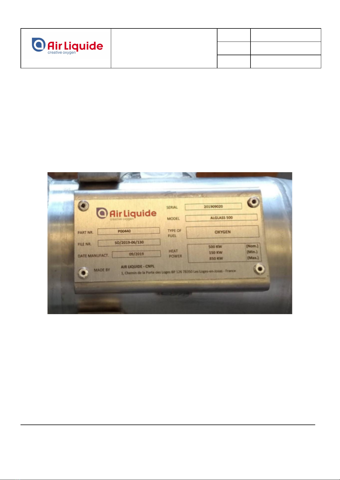
Each burner metal component part bears its production file number.
The burner block is refractory material. This refractory material is chosen to be compatible with the
particular glass making process and the type of superstructures.
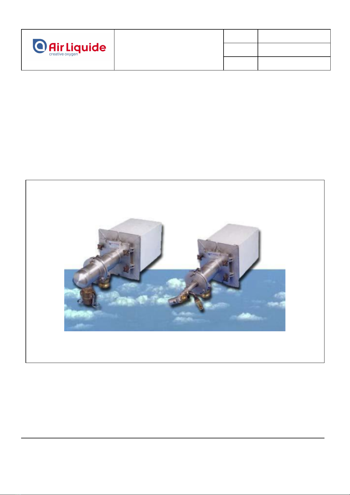
The gaseous fuel version of the ALGLASS burner comprises six component parts, and the liquid fuel
version comprises five parts.
The gas/fuel oil burner consists of the following parts. (Fig.1)
●The burner block made of refractory material.
●The fixation system for mounting the burner body on the block, consisting of two half sections.
●A ceramic packing to be positioned between the burner block and the burner body.
●The burner body with its VITON O-ring, mounted in the flange groove and a closing flange to be
mounted back on the body.
●A gas lance with 1, 3 or 5 tubes.
●A dual lance with injector and nozzle
All data shown on this page are subject to change without notice.
This document contains proprietary information of AIR LIQUIDE.
They cannot be copied nor disclosed to a third party without its previous consent.
Page 7 / 22

ALGLASS GAS/DUAL BURNER
SAFETY INSTRUCTIONS FOR USE
AND MAINTENANCE
Reference:
CNPL-IOM-001-CNPL-A
Revision:
1
Date:
02/04/2020
FIGURE 1
All data shown on this page are subject to change without notice.
This document contains proprietary information of AIR LIQUIDE.
They cannot be copied nor disclosed to a third party without its previous consent.
Page 8 / 22

ALGLASS GAS/DUAL BURNER
SAFETY INSTRUCTIONS FOR USE
AND MAINTENANCE
Reference:
CNPL-IOM-001-CNPL-A
Revision:
1
Date:
02/04/2020
E . BURNER SPECIFICATIONS
MODEL
ALGLASS GAS/DUAL 200
ALGLASS GAS/DUAL 500
Max. Comb. Cap.
350 kW
850 kW
Nom. Comb. Cap.
200 kW
500 kW
Min. Comb. Cap.
70 kW
150 kW
MODEL
ALGLASS GAS/DUAL 1000
Max. Comb. Cap.
1750 kW
Nom. Comb. Cap.
1000 kW
Min. Comb. Cap.
300 kW
All data shown on this page are subject to change without notice.
This document contains proprietary information of AIR LIQUIDE.
They cannot be copied nor disclosed to a third party without its previous consent.
Page 9 / 22

ALGLASS GAS/DUAL BURNER
SAFETY INSTRUCTIONS FOR USE
AND MAINTENANCE
Reference:
CNPL-IOM-001-CNPL-A
Revision:
1
Date:
02/04/2020
Gas version:
BURNER MODEL
ALGLASS GAS
200
ALGLASS GAS
500
ALGLASS
GAS 1000
Min. oxygen temperature (°C) at burnet
inlet
10 °C
Max. oxygen temperature (°C) at burnet
inlet
40 °C
Min. Natural gas temperature (°C) at burnet
inlet
10 °C
Max. Natural gas temperature (°C) at
burnet inlet
40 °C
Min. oxygen supply pressure (mbar g.) at
burnet inlet
25 mbar g. (Max. oxygen pressure drop through
the burner at the maximum recommended firing
rate)
Min. Natural gas supply pressure (mbar g.)
at burnet inlet
100 mbar g. (Max. Natural gas pressure drop
through the burner at the maximum
recommended firing rate)
Cooling air flow rate (Nm3/h)
12 Nm3/h
30 Nm3/h
60 Nm3/h
All data shown on this page are subject to change without notice.
This document contains proprietary information of AIR LIQUIDE.
They cannot be copied nor disclosed to a third party without its previous consent.
Page 10 / 22

ALGLASS GAS/DUAL BURNER
SAFETY INSTRUCTIONS FOR USE
AND MAINTENANCE
Reference:
CNPL-IOM-001-CNPL-A
Revision:
1
Date:
02/04/2020
Dual version:
BURNER MODEL
ALGLASS DUAL 200
ALGLASS DUAL 500
ALGLASS DUAL 1000
Min. oxygen temperature (°C)
at burnet inlet
10 °C
Max. oxygen temperature (°C)
at burnet inlet
40 °C
Min. fuel oil temperature (°C) at
burnet inlet
100 °C
Max. fuel oil temperature (°C)
at burnet inlet
140 °C
Min. oxygen supply pressure
(mbar g.) at burnet inlet
25 mbar g. (Max. oxygen pressure drop through the burner at the
maximum recommended firing rate)
Max. oxygen supply pressure
(mbar g.) at burnet inlet
25 mbar g. (Max. oxygen pressure drop through the burner at the
maximum recommended firing rate)
Min. fuel oil supply pressure
(bar g.) at burnet inlet
2 bar g.
Max. fuel oil supply pressure
(bar g.) at burnet inlet
5 bar g.
Max. fuel oil viscosity (cst) at
burner inlet
40 centistokes
Nominal fuel oil viscosity (cst)
at burner inlet
25 centistokes
Min. atomizing air pressure
(bar g.) at burner inlet
2 bar g.
Max. atomizing air pressure
(bar g.) at burner inlet
5 bar g.
Atomizing air flow
5 ~ 15 mass % fuel oil
Cooling air flow rate (Nm3/h)
12 Nm3/h
30 Nm3/h
60 Nm3/h
All data shown on this page are subject to change without notice.
This document contains proprietary information of AIR LIQUIDE.
They cannot be copied nor disclosed to a third party without its previous consent.
Page 11 / 22

ALGLASS GAS/DUAL BURNER
SAFETY INSTRUCTIONS FOR USE
AND MAINTENANCE
Reference:
CNPL-IOM-001-CNPL-A
Revision:
1
Date:
02/04/2020
F . BURNER CHOICE
1 ) FLAME LENGTH
Gas version: basically, this burner can adjust flame length changing the gas lance between 1, 3, 5 tubes
geometry. More tubes make a shorter flame.
Dual version: basically, this burner can adjust flame length using adjusting atomizing air pressure
Attention : flame shape could be changed with oil viscosity. Please adjust suited viscosity.
2 ) COOLING AIR
During combustion, the burner body, gas lance and burner block are cooled by the fluid used for
combustion.
However, when combustion is off, all parts of burner are heated.
In this case, put into cooling air using oxygen line.
Atomizing air is not only atomizing but also to cool down oil lance.
Never stop the atomizing air while oil lance is located in burner block and hot furnace.
3 ) BURNER BLOCK
The usual size of the burner block is 220 x 220 mm .The size of the furnace opening should be more than
this dimension.
All data shown on this page are subject to change without notice.
This document contains proprietary information of AIR LIQUIDE.
They cannot be copied nor disclosed to a third party without its previous consent.
Page 12 / 22

ALGLASS GAS/DUAL BURNER
SAFETY INSTRUCTIONS FOR USE
AND MAINTENANCE
Reference:
CNPL-IOM-001-CNPL-A
Revision:
1
Date:
02/04/2020
G . INSTALLATION AND ASSEMBLY
The main difference between the Gas and Dual ALGLASS burner version resides in the fuel lance.
Their assembly and installation procedures are therefore practically the same.
The burner block and adapters must be pre-assembled before installing on the furnace.
On a recently built furnace, burner block will be installed on the furnace before starting heating up.
1 ) INSTALLING THE BURNER ADAPTER
Before installing the burner block, check that the support of the block is horizontal or inclined a few angle
towards the glass level, to be sure that flame are not oriented towards the crown of the furnace.
●Install the two half-sections adapter on the block with the attached bolts and tighten moderately
Setting of the fixation system
.
All data shown on this page are subject to change without notice.
This document contains proprietary information of AIR LIQUIDE.
They cannot be copied nor disclosed to a third party without its previous consent.
Page 13 / 22

ALGLASS GAS/DUAL BURNER
SAFETY INSTRUCTIONS FOR USE
AND MAINTENANCE
Reference:
CNPL-IOM-001-CNPL-A
Revision:
1
Date:
02/04/2020
●Place the burner block with its adapter in their opening and push them into their final position,
tighten the devices for securing the block in place.
●Plug the hole in the block with an alumina wool plug.
2 ) ASSEMBLY OF A BURNER BODY
First of all, for safety reason it is essential that all traces of grease must be removed from the metal burner
parts, before O-ring are installed, to avoid accidental combustion.
Before this burner is run, the burner body will be mounted on the block.
Then, for operating with fuel, the assembly procedure is as follows :
●Please make sure that Viton O-ring is set to the burner body.
●Check the oxygen connection.
●Check the oxygen supply.
●Mount the 3 mm thick, 140 x 140 mm square ceramic packing on the burner body nozzle.
●Mounting the blind flange by using the attached 3 bolts.
●Remove the alumina wool plug from the block and place the burner body nozzle in the hole of the
block.
Mounting of the body
All data shown on this page are subject to change without notice.
This document contains proprietary information of AIR LIQUIDE.
They cannot be copied nor disclosed to a third party without its previous consent.
Page 14 / 22

ALGLASS GAS/DUAL BURNER
SAFETY INSTRUCTIONS FOR USE
AND MAINTENANCE
Reference:
CNPL-IOM-001-CNPL-A
Revision:
1
Date:
02/04/2020
●Place the tie-rods in the burner body plate slots and tighten them to compress the ceramic paper
seal.
●Mount oxygen flex tube.
●Put into Cooling Air
3 ) MOUNTING THE GAS LANCE ON THE BURNER
The gas lance will be assembled to the burner body when ready for igniting the burner.
The assembly procedure is as follows:
●Please make sure that Viton O-ring is set to the gas feeder.
●Don't switch off the cooling air supply until combustion is start.
●Dismount the blind flange while taking precautions to protect yourself from the hot gas that may be
expelled due to positive furnace pressure.
●Place the gas lance in the burner body.
Mounting of the gas lance
●Adjust the gas feeder.
●Place the tie-rods in the flange slots and tighten them to seal the O-ring.
●Connect the gas hose to gas feeder.
●The burner may be ignited, according to the procedure described in the operation manual of
combustion control system.
All data shown on this page are subject to change without notice.
This document contains proprietary information of AIR LIQUIDE.
They cannot be copied nor disclosed to a third party without its previous consent.
Page 15 / 22

ALGLASS GAS/DUAL BURNER
SAFETY INSTRUCTIONS FOR USE
AND MAINTENANCE
Reference:
CNPL-IOM-001-CNPL-A
Revision:
1
Date:
02/04/2020
4 ) MOUNTING THE DUAL LANCE ON THE BURNER
ASSEMBLING THE FUEL OIL LANCE:
Dual lance composition
●Set the couplers and flex hoses to the oil port (¼”) and atomization air port (⅜”).
●As for the attached coupler, female part has check valve. So please set female parts to lance and
male parts to flex hose.
●Insert the O-ring on the fuel oil injector (only available for ALGLASS DUAL 1000).
●Screw the fuel oil injector on the DUAL lance tip and squeeze it to assure the tightness.
●Mount the nozzle on the fuel oil lance tip and squeeze to fix it without any tools.
●Check that the calibrated orifice is in place in the external air circuit.
Atomizing fluid circuit
All data shown on this page are subject to change without notice.
This document contains proprietary information of AIR LIQUIDE.
They cannot be copied nor disclosed to a third party without its previous consent.
Page 16 / 22

ALGLASS GAS/DUAL BURNER
SAFETY INSTRUCTIONS FOR USE
AND MAINTENANCE
Reference:
CNPL-IOM-001-CNPL-A
Revision:
1
Date:
02/04/2020
MOUNTING THE DUAL LANCE IN THE BODY:
The fuel oil lance will be assembled to the burner body when ready for igniting the burner.
First, check that the fuel oil lance is correctly assembled.
The assembly procedure is as follows:
●Connect oil and atomizing air flex tubes to each inlet.
●First, put into atomizing air .
●Don't switch off the cooling air supply until combustion is started.
●Dismount the blind flange while taking precautions to protect yourself from the hot gas that may be
expelled due to positive furnace pressure.
●Place the fuel oil lance in the burner body. The lance attached angle is changeable.
Mounting of the lance
●Place the tie-rods in the flange slots and tighten them to seal the O-ring.
●The burner may be ignited, according to the procedure described in the operation manual of combustion
control system.
All data shown on this page are subject to change without notice.
This document contains proprietary information of AIR LIQUIDE.
They cannot be copied nor disclosed to a third party without its previous consent.
Page 17 / 22

ALGLASS GAS/DUAL BURNER
SAFETY INSTRUCTIONS FOR USE
AND MAINTENANCE
Reference:
CNPL-IOM-001-CNPL-A
Revision:
1
Date:
02/04/2020
H . IGNITION AND EXTINCTION PROCEDURE
1 ) IGNITION
According to the previous section, at this moment, the burner is ready to ignite. There is air cooling flow on
the burner and atomizing air if Dual lance is used.
●Check oxygen and gas valves position on piping.
●Flow oxygen in burner at minimum value (30% of nominal) and stoichiometric gas (using manual mode
or automatic sequence of PID)
●Check the ignition of the flame
●When oxygen flow exceeds 30% of the rating, close the air cooling valve
●Adjust atomizing fluid pressure depending on the flame length if Dual lance is used
2 ) EXTINCTION
To stop a burner , decrease the power around 30% of the rating,
When stopping burners, observe the following sequence and fluid flow conditions:
●Decrease the power around 30% of the rating,
●Close the gas valve nearest to the burner
●Check that the burner is off
●Open air cooling valve and check flow
●Close oxygen valve
●if Dual lance is used:
○Decrease atomizing fluid pressure until 1 bar to purge oil in the lance
○Just before removing the oil lance, close atomizing air valve
●Remove the gas/Dual lance and plug using blind flange
All data shown on this page are subject to change without notice.
This document contains proprietary information of AIR LIQUIDE.
They cannot be copied nor disclosed to a third party without its previous consent.
Page 18 / 22

ALGLASS GAS/DUAL BURNER
SAFETY INSTRUCTIONS FOR USE
AND MAINTENANCE
Reference:
CNPL-IOM-001-CNPL-A
Revision:
1
Date:
02/04/2020
I . MAINTENANCE OPERATION
It may necessary to dismount a burner for the following two main reasons :
- Maintenance check or replacement of the lance
- Decommissioning
The dismounting procedures are complementary for these two situations and are described thereafter.
1 ) MAINTENANCE CHECK OR REPLACEMENT OF THE GAS/DUAL LANCE
To shut down the burner
Gas version:
●Close the gas valve nearest to the burner
●Check that the burner is off
●Put into Cooling Air
●Remove the lance and plug using blind flange
●Close the oxygen valve
●Check the lance and replace it if necessary
●Install the lance following the procedure described in the G.3.
Dual version:
●Close the fuel oil valve nearest to the burner.
●Check that the burner is off.
●Put into Cooling Air.
●Purge oil in lance.
●Remove the fuel oil lance and plug using blind flange.
●Close the atomizing air valve.
●Close the oxygen valve.
●Check the lance and injector and replace them if necessary.
●Install the fuel oil lance following the procedure described in the G.4.
This maintenance operation must be done every 3 weeks
All data shown on this page are subject to change without notice.
This document contains proprietary information of AIR LIQUIDE.
They cannot be copied nor disclosed to a third party without its previous consent.
Page 19 / 22

ALGLASS GAS/DUAL BURNER
SAFETY INSTRUCTIONS FOR USE
AND MAINTENANCE
Reference:
CNPL-IOM-001-CNPL-A
Revision:
1
Date:
02/04/2020
2 ) TAKING THE BURNER OUT OF SERVICE
Remove the lance as above mentioned.
●Close all valves nearest to the burner
●Remove the burner body
●Plug the block hole with a refractory material plug
All data shown on this page are subject to change without notice.
This document contains proprietary information of AIR LIQUIDE.
They cannot be copied nor disclosed to a third party without its previous consent.
Page 20 / 22
This manual suits for next models
2
Table of contents
Popular Burner manuals by other brands

Bentone
Bentone Bentoflex ST 133 KL Installation and maintenance instruction

EcoSmart Fire
EcoSmart Fire AB8 quick start guide

bene casa
bene casa BC-74621 user manual

Riello
Riello MODULO 32 DIR quick start guide

Weishaupt
Weishaupt WG10 Series manual

Bentone
Bentone B 45 A2.2R Installation and maintenance instruction

Weil-McLain
Weil-McLain CG Series 10 Specifications

Riello
Riello RS 300/O2 BLU Installation, use and maintenance instructions

PVI Industries
PVI Industries FIREPOWER PV500-9 user manual

Campingaz
Campingaz CAMPING DUO PLUS CV manual

Cook's Companion
Cook's Companion B407324 Care and use

baltur
baltur BGN 34 P Instruction