manuals.online logo
Brands
  1. Home
  2. •
  3. Brands
  4. •
  5. Air Specialties Express
  6. •
  7. Fan
  8. •
  9. Air Specialties Express VCDK090C User manual

Air Specialties Express VCDK090C User manual

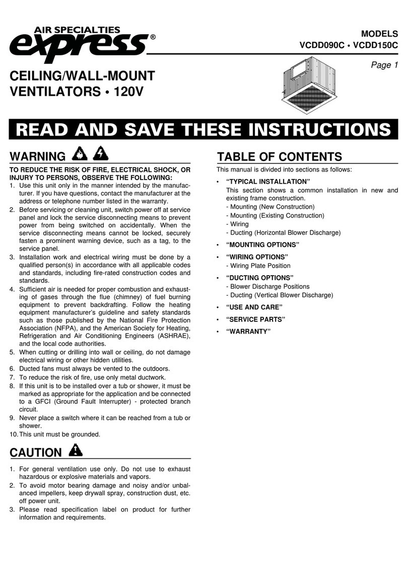
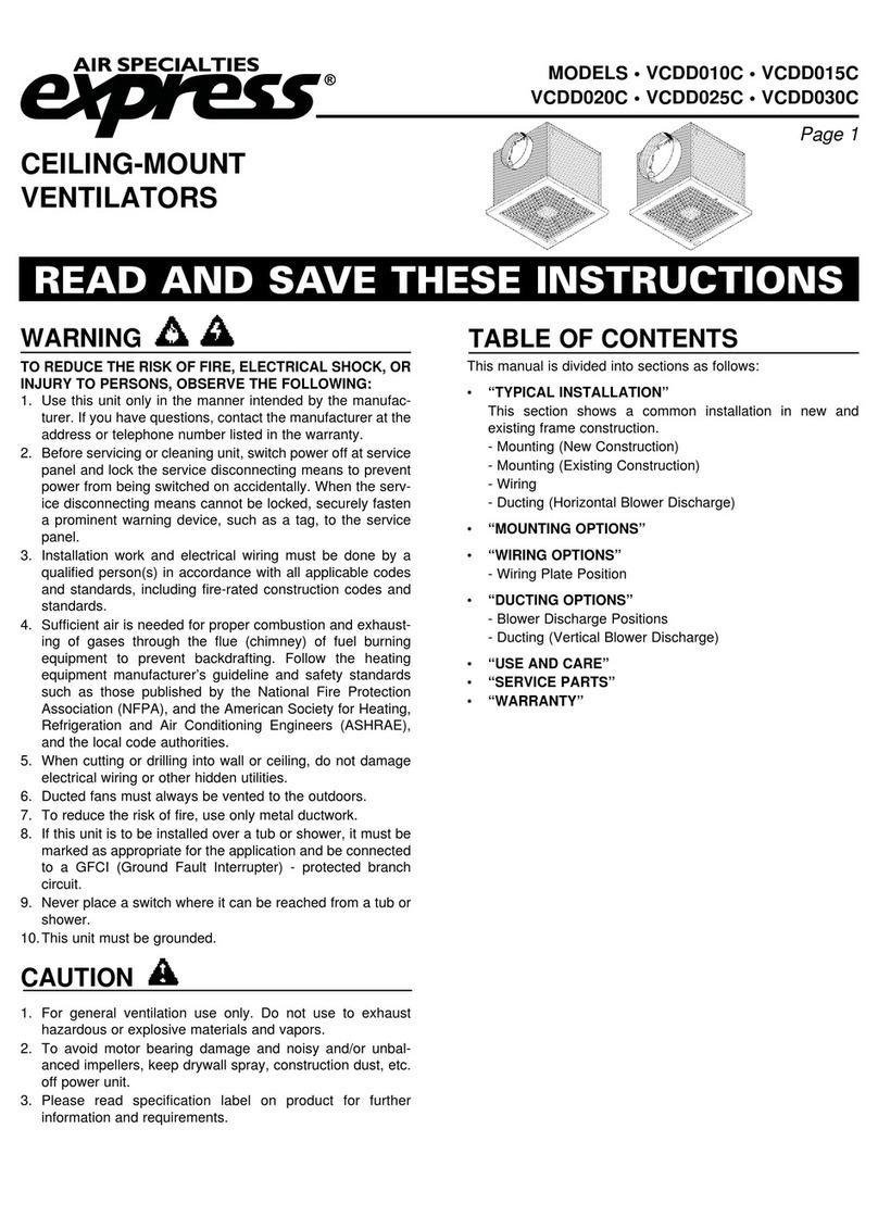
MODELS
VCDK090C • VCDK130C • VCDK170C
Air Specialties Express, 448 S. Main St., P. O. Box 930040, Verona, WI 53593-0040 Phone: (877)945-9175 Fax: (608)845-6470 www.airspecialties.com
CEILING/WALL-MOUNT
VENTILATORS • 120V
READ AND SAVE THESE INSTRUCTIONS
WARNING
CAUTION
TABLE OF CONTENTS
TO REDUCE THE RISK OF FIRE, ELECTRICAL SHOCK, OR
INJURY TO PERSONS, OBSERVE THE FOLLOWING:
1.
2.
3.
4.
5.
6.
7.
8.
9.
10.
Use this unit only in the manner intended by the manufac-
turer. If you have questions, contact the manufacturer at the
address or telephone number listed.
Before servicing or cleaning unit, switch power off at service
panel and lock the service disconnecting means to prevent
power from being switched on accidentally. When the serv-
ice disconnecting means cannot be locked, securely fasten
aprominent warning device, such as a tag, to the service
panel.
Installation work and electrical wiring must be done by a
qualified person(s) in accordance with all applicable codes
and standards, including fire-rated construction codes and
standards.
Sufficient air is needed for proper combustion and exhaust-
ing of gases through the flue (chimney) of fuel burning
equipment to prevent backdrafting. Follow the heating
equipment manufacturer’s guidelines and safety standards
such as those published by the American Society for
Heating, Refrigeration and Air Conditioning Engineers
(ASHRAE), and the local code authorities.
When cutting or drilling into wall or ceiling, do not damage
electrical wiring and other hidden utilities.
Ducted fans must always be vented to the outdoors.
To reduce the risk of fire, use only metal ductwork.
If this unit is to be installed over a tub or shower, it must be
marked as appropriate for the application and be connected
to a GFCI (Ground Fault Interrupter) - protected branch cir-
cuit.
Never place a switch where it can be reached from a tub or
shower.
This unit must be grounded.
1.
2.
3.
For general ventilating use only. Do not use to exhaust haz-
ardous or explosive materials and vapors.
To avoid motor bearing damage and noisy and/or unbal-
anced impellers, keep drywall spray, construction dust, etc.
off power unit.
Please read specification label on product for further infor-
mation and requirements.
•
•
•
•
•
“TYPICAL INSTALLATION”
This sections shows a common installation in new and
existing, frame construction.
-Mounting (new construction)
-Mounting (existing construction)
-Wiring
-Ducting (straight-through blower discharge)
“DUCTING OPTIONS”
-Blower Discharge Positions
-Ducting (right-angle blower discharge)
“USE AND CARE”
“WARRANTY”
“SERVICE PARTS”
This manual is divided into sections as follows:
ASX-11218-A, Page 1
MODELS
VCDK090C • VCDK130C • VCDK170C
TYPICAL INSTALLATION
MOUNTING
(New Frame Construction)
TYPICAL INSTALLATION
WIRING - 115V, 60 Hz., 1 Phase
12” ROUND
DUCT
Grille
Screw
9-3/8” x 12-3/4” TO
10” ROUND TRANSITION
MOUNTING
BRACKETS
factory-shipped
in position for
1/2” ceiling
material.
CEILING
JOIST
(24” Centers
Shown)
Factory-shipped unit installed in new construction.
FINISHED
CEILING
MATERIAL
9-3/8” x 12-3/4” TO
12” ROUND
TRANSITION
MOUNTING
SCREWS
CEILING
JOIST
(24” Centers
Shown)
Factory-shipped unit installed in existing construction.
MOUNTING
(Existing Frame Construction)
Ventilator factory-shipped
in horizontal
discharge position
2
Use U.L. approved connectors to wire per local codes. Connect
ground wire to bottom of conduit box.
IMPORTANT:
Remove shipping tape from damper.
Remove the shipping tape from the damper flap and make sure
that damper flap opens and closes freely inside the ductwork.
Use duct tape to make ductwork connections secure and air-tight.
Ventilator
factory-
Shipped
in horizontal
discharge
position
GRILLE
(Installs after ceiling finished)
MOUNTING BRACKETS
factory-shipped in position
for 1/2” ceiling material
GRILLE
SCREW
GRILLE
12” ROUND
DUCT
UNIT SIZE WIRE CONNECTION
YELLOW TO L1, ORANGE TO L2
SEPARATE BROWN AND INSULATE
SEPARATE BLUE AND INSULATE
YELLOW TO L1, BROWN TO L2
SEPARATE ORANGE AND INSULATE
SEPARATE BLUE AND INSULATE
YELLOW TO L1, BLUE TO L2
SEPARATE ORANGE AND INSULATE
SEPARATE BROWN AND INSULATE
INSTALL INLINE BETWEEN L2
AND ORANGE, BROWN OR BLUE
CORRESPONDING TO UNIT
SIZE
170
130
090
Speed
Control
DUCTING OPTIONS
BLOWER DISCHARGE POSITIONS
Horizontal discharge
position. (Factory Shipped)
Vertical discharge
position.
DUCT CONNECTOR
(This Side) DUCT
CONNECTOR
(This Side)
Cabinet Disassembled,
Rotated Then Reassembled
With Opening As Shown
MODELS
VCDK090C • VCDK130C • VCDK170C
WARRANTY
3
Seller warrants products manufactured by it and supplied here-
under to be free from defects in materials and workmanship under
normal use and proper maintenance for a period of twelve months
from date of shipment. If within such period any such products
shall be proved to Seller’s reasonable satisfaction to be defective,
such products shall be repaired or replaced at Seller’s option.
Seller's obligation and Buyer’s exclusive remedy hereunder shall
be limited to such repair and replacement and shall be condi-
tioned upon Seller’s receiving written notice of any alleged
defects no later than 10 days after its discovery within the war-
ranty period and, at Seller’s option, the return of such products to
Seller, f.o.b. its factory, when such return is feasible. Seller
reserves the right to satisfy its warranty obligation in full by reim-
bursing Buyer for all payments it makes hereunder, and Buyer
shall thereupon return the products to Seller. Seller shall have the
right to remedy such defects.
THE FOREGOING WARRANTIES ARE EXCLUSIVE AND
IN LIEU OF ALL OTHER EXPRESS AND IMPLIED WAR-
RANTIES (EXCEPT TO TITLE) INCLUDING BUT NOT LIMITED
TO IMPLIED WARRANTIES OF MERCHANTABILITY FITNESS
FOR A PARTICULAR PURPOSE, PERFORMANCE, OR OTH-
ERWISE, and in no event shall the Seller be liable for claims
(based upon breach of express or implied warranty, negligence,
product liability, or otherwise) for any other damages, whether
direct, immediate, incidental, foreseeable, consequential, or spe-
cial.
USE AND CARE
Ventilator is designed for continuous operation. If desired, it may
be controlled using an on/off switch or a solid-state, variable
speed control. Follow wiring instructions packed with control,
and adhere to all local and state codes, and the National
Electrical Code.
To clean blower assembly: Remove grille, disassemble two
cabinet halves, unplug blower from housing, remove blower
mounting nuts, and carefully remove blower from housing. Use
appropriate vacuum attachment or a soft cloth and mild soap or
detergent to clean blower discharge area and wheel. DO NOT
ALLOW WATER TO ENTER THE MOTOR. Make sure blower
assembly is completely dry before reinstalling.
Motor is permanently lubricated. Do not oil or disassemble
motor.
WARNING: To reduce the risk of electric shock,
disconnect from power supply before servicing.
DUCTING
(Vertical blower discharge)
ROOF CAP
12”
ROUND
DUCT
9-3/8” x 12-3/4”
TO 10” ROUND
TRANSITION
Typical ductwork connection to a ventilator converted to
vertical discharge.
Two ways to connect ductwork to a factory-shipped unit.
DUCTING
(Horizontal blower discharge)
9-3/8” x 12-3/4” TO
12” ROUND
TRANSITION
12” ROUND
ELBOW WALL
CAP
12”
ROUND
DUCT
ROOF CAP
MODELS
VCDK090C • VCDK130C • VCDK170C
SERVICE PARTS SERVICE PARTS
KEY NO. PART NO. DESCRIPTION QTY. REQ.
1 384-9201 Mounting Bracket 4
2 998-0028 Screw — #10 x 3/4” Self Drilling 5
3 999-6313 7 MFD Capacitor 1
4 402-2681 Capacitor Strap 1
5 992-3371 Motor (1/2 HP, 3 Speed) 1
6 999-0069 Screw — 1/4-20 x 3/4” 3
7 999-2565 Blower Assembly (10 x 8) 1
8 384-9102 Fan Panel 1
9 384-9122 Discharge Flange 1
10 999-4701 Nut — 1/4-20 8
11 384-9142 Pivot Rod 1
12 384-9132 Damper Blade 1
13 999-0022 Screw — #10 x 1/2” 6
14 384-9181 Conduit Box 1
15 999-9916 Cable Connector 1
16 999-0040 HHCS — 1/4-20 x 7/8” 4
17 384-9112 Ceiling Fan Housing 1
18 384-9162 Housing Angle 1
19 384-9212 Perforated Steel Grille 1
20 999-9928 Cover Plate 1
21 901-0740 Screw Pkg 1
7
4
10
11
21
20
18
17
13
12 14
15
16
10
19
2
2
13
5
6
Order replacement parts by PART NO. - not by KEY NO.
9
8
448 South Main Street
P. O. Box 930040
Verona, WI 53593-0040
Phone: 877.945.6470 • Fax: 608.845.6470 • www.AIRSPECIALTIES.com
4

This manual suits for next models

2

Other Air Specialties Express Fan manuals

Air Specialties Express VCDD010C User manual

Air Specialties Express

Air Specialties Express VCDD010C User manual

Air Specialties Express VE Assembly instructions

Air Specialties Express

Air Specialties Express VE Assembly instructions

Air Specialties Express VCDD040I User manual

Air Specialties Express

Air Specialties Express VCDD040I User manual

Air Specialties Express VCDD090C User manual

Air Specialties Express

Air Specialties Express VCDD090C User manual

Popular Fan manuals by other brands

Gaggenau AL 400 721 use and care manual

Gaggenau

Gaggenau AL 400 721 use and care manual

ROWAN ELECTRIC APPLIANCE 5375 instruction manual

ROWAN ELECTRIC APPLIANCE

ROWAN ELECTRIC APPLIANCE 5375 instruction manual

Bo-Camp 8520952 instruction manual

Bo-Camp

Bo-Camp 8520952 instruction manual

Vents TT user manual

Vents

Vents TT user manual

Zehnder Rittling ComfoAir E 350 quick guide

Zehnder Rittling

Zehnder Rittling ComfoAir E 350 quick guide

Lunos 3/UP-AS Technical Information Sheet

Lunos

Lunos 3/UP-AS Technical Information Sheet

Vectaire AS Series Installation and operating instructions

Vectaire

Vectaire AS Series Installation and operating instructions

Makita DCF102Z owner's manual

Makita

Makita DCF102Z owner's manual

Panasonic PAW-FC Installation and maintenance manual

Panasonic

Panasonic PAW-FC Installation and maintenance manual

NuTone 765H110L installation guide

NuTone

NuTone 765H110L installation guide

Craftmade Freestyle installation guide

Craftmade

Craftmade Freestyle installation guide

Lasko C27100 Important instructions & operating manual

Lasko

Lasko C27100 Important instructions & operating manual

Oceanic OCEAVB100W2 owner's manual

Oceanic

Oceanic OCEAVB100W2 owner's manual

Hunter Rhinebeck 50769 installation manual

Hunter

Hunter Rhinebeck 50769 installation manual

S&P EDM-80L Operating and installation instructions

S&P

S&P EDM-80L Operating and installation instructions

PAX Passad 00 User and installation guide

PAX

PAX Passad 00 User and installation guide

Eberg TIK user manual

Eberg

Eberg TIK user manual

Crane EE-5605 instruction manual

Crane

Crane EE-5605 instruction manual

manuals.online logo
manuals.online logoBrands
  • About & Mission
  • Contact us
  • Privacy Policy
  • Terms and Conditions

Copyright 2025 Manuals.Online. All Rights Reserved.