Air TEc MASTER 35 User manual

MASTER 35
®
PETROL/GASOLINE IMPACT WRENCH
CouperStreet,Glasgow G40DLUnitedKingdom
Tel: 44(0) 1415525591
Fax: 44(0)1415525064
E-mail: enquiries@airtecintl.co.uk
This full Manual can be downloaded from our website www.airtecinternational.com in
English, French, German & Spanish

MASTER35
®
PETROL/GASOLINEIMPACTWRENCH
MAINTENANCE MANUAL
CONTENTS
DESCRIPTION PAGE NUMBER
Uses & Technical Information 1
Safety Precautions 2
Operating Controls - Illustrations 3
Operating Controls - Instructions for use 4
Start/Stop Operation 5
Routine Service 6
Dismantling Motor 7
Motor Parts List and Exploded Diagrams 8,9, 10
Motor Conversion Kit Parts List 11
Motor Notes 12
Dismantling Impact Unit 13
Gearbox Exploded Diagram Drawing and Parts List 14 & 15
Impact Unit & Carrying Handle
Exploded Diagram Drawing and Parts List 16
Gearbox and Impact Unit Notes 17
Roll Bar Handle Kit 18
Fault Finding 19
Workshop Equipment 20
Accessories 21
Index 22 & 23
Copyright Airtec International Ltd
©
". All Rights Reserved.
No reproduction of whole or part of this Manual is allowed without
written Permission of Copyright.
Airtec International Limited, Couper Street, Glasgow G4 0DL, U.K. Edition June 2006
E-mail: enquiries@airtecintl.co.uk

1. USES
The Master Impact Wrench is ideal for removing/fitting Chairscrews (Lag Screws) and Fishplates (Joint
Bars) where track possession is not possible, if there are access difficulties or if other sources of power
e.g. Air Compressors, Generators or Power Packs are not available. The Master can drill holes in
Wooden Sleepers (Ties) using our Safety Quick Release Attachment which allows the fitting/removal of
Auger Bits in seconds.
Fasteners can be removed/fitted in approximately five seconds.
2. TECHNICAL INFORMATION
1. TORQUE RANGE
500 - 1800 Nm (350 to 1325 Ft/lbs) using five
position lever settings
2. BOLT CAPACITY
16 to 32mm (5/8" to 1
1
/4")
3. DIMENSIONS
Length 570mm (22
3
/8")
Height 270mm (10
5
/8")
Width 445mm (17 ½”)
4. ENGINE - Two stroke/cycle Special
Airtec EMAK 056 56 c.c.
Maximum free speed 12,000 R.P.M.
Fuel Tank capacity 0.7 litres (1.20 pints)
Running time on full tank of fuel 60
Minutes
Fuel Mixture ratios
Petrol/Gasoline Unleaded minimum 90
Octane and two stroke oil
MIX RATIO MLS. PER
LITRE
OIL (OZS.PER)
(US GAL.)
Mineral 25:1 40 3
Synthetic 50:1 20 1
1
/2
5. EXHAUST EMISSION LEVELS
CO2 90g/Hph
HC 110g/Hph
6. GEARBOX
Fill with 0.25 Litre (0.44 pints) of Esso
Spartan EP68 Gear Oil or equivalent to half
way up sight glass with Wrench in the
horizontal position.
When new, change oil after 1 hours use,
after 5 hours and then every 30 hours.
7. IGNITION - Electronic Selectra
Spark Plug Champion RCJ-7Y or
equivalent
Spark Plug gap 0.5 to 0.6mm
8. IMPACT MECHANISM
Fill with 130 grammes (4
1
/2oz) of
Molybdenum Disulphate Grease, Castrol
MS3, Klubern12MF or equivalent Grade 2
quality.
9. NOISE
Acoustic pressure (LpA) readings
Idling 87 : dB(A)
Acoustic power (LWA) according to
ISO 3746 Idling 96 : dB(A)
Under very extreme working conditions the
machine can reach 103 & 112 : dB(A)
respectively.
10. SQUARE DRIVE
Standard 1"
11. VIBRATIONbasedon actualontrack tests
Can vary between 7.0 and 11.6 m/s2
depending on operator technique and
condition of Wrench, fastener and track but
because the Wrench is so fast operator
exposure is minimised.
It would be possible to fit/remove
approximately 330 fasteners in an eight hour
working day before reaching the Action
Exposure level at 11.6 m/s2.
The main source of vibration comes from
technique and Socket and Fastener. Keep
Fastener, Socket and Wrench in a straight
line and ensure all are kept in good
condition.
12. WEIGHT
18.3 Kgs (40 1/3 lbs)

3. SAFETY PRECAUTIONS
BEFOREusing the Impact Wrench read these safetyinstructions CAREFULLYand ensure
you fully UNDERSTAND them. DO NOT allow untrained personnel to use the Wrench.
1. Wear suitable PROTECTIVE CLOTHING,
safety boots, goggles, gloves and ear
protection according to Company rules,
working conditions or Government/State
Legislation.
Use of gloves may help prevent injury by
keeping hands warm and dry.
For maximum safety wear ear protection
within a 16 metre (17
1
/2yards) distance of
Wrench.
2. FILL the fuel tank carefully BEFORE starting
the Wrench and avoid spillage. Use the Fuel
Funnel provided and DO NOT fill or add oil
while the Motor is running, if the tank is hot
or it is close to any naked flames. Mix the
quantity needed. Do not leave the mixture in
the fuel tank or container for a prolonged
period of time.
3. Use only IMPACT QUALITY Sockets and
Accessories.
Using worn Sockets on a good Square Drive
or good Sockets on a worn Square Drive will
increase vibration levels with resultant
damage to both operator and Wrench. HAND
Sockets must NEVER be used.
4. Use Rubber Rings and Steel Pins or other
suitable retaining devices to retain the
Socket or Accessoryonto the Square Drive.
DO NOT use twigs, wire, nails or plastic
straps.
5. Check the Wrench for damage
regularly. Ensure fasteners are tight at
all times.
A poorly maintained Wrench will be
inefficient and produce extra noise and
vibration.
6. Check pull cord is not frayed nor worn.
7. Know where the controls are and how to
use them and be able to STOP the Wrench
quickly in an emergency.
8. Do not wear hanging jewellery, a tie or
LOOSE or torn clothing when using
equipment.
9. DO NOT operate the Wrench in a
CONFINED area, where exhaust fumes
(CARBON MONOXIDE) may collect.
10. Set the GEAR CONTROL in NEUTRAL
before starting.
11. Take up a FIRM footing and maintain a
balanced body position.
12. Switch OFF ENGINE BEFORE transporting
the Wrench to another location.
13. Take CARE when LIFTING or carrying the
Wrench - weight with fuel and excluding
accessory 18.3 Kgs (40 1/3 lbs).
14. Remove FUEL FILLER CAP CAREFULLY as
pressure can build up in the tank. This is very
important in warm weather, if the Wrench has
been left in an exposed area or after
prolonged periods of use.
15. Always auger or fit fasteners on one of
the LOW torque settings and use a HIGH
one for removing fasteners.
SAFETY ISEVERYONE'SRESPONSIBILITY
THINK, ACT,BESAFE

4. OPERATINGCONTROLS
(1)
ON/OFFCONTROL SWITCH
(5)
THROTTLETRIGGER
(9)
TORQUE SETTINGLEVER
(2) FUELPRIMER BULB (6) HALF SPEED LEVER (10) OILFILLERCAP
(3) CHOKELEVER (7) FORWARD/REVERSE
CONTROLKNOB (11) FUELFILLERCAP
(4)
RECOILSTARTER
(12)
DE
-
COMPRESSIONBUTTON
(8) SQUAREDRIVE
(1)
ON/OFF CONTROL SWITCH
(5) THROTTLE TRIGGER
(9) TORQUE SETTING LEVER
(2) FUEL PRIMER BULB (6) HALF SPEED LEVER (10) OIL FILLER PLUG
(3) CHOKE LEVER (7) FORWARD/REVERSE/ (11) FUEL FILLER CAP
(4) RECOIL STARTER NEUTRAL CONTROL KNOB (12) DE-COMPRESSION BUTTON
(8) SQUARE DRIVE
Note : The Serial Number can be found on Gearbox Casing, between Control Knob (7) and Oil Filler Cap (10)

5. OPE RATI N G CO NTRO LS (See Page 3 for easy identification).
1. ON/OFF CONTROL SWITCH
To START, move the switch to I.
To STOP move to STOP.
2. FUEL PRIMER BULB
Makes starting easy.
Press bulb three/four times before using
recoil starter handle.
3. CHOKE LEVER
Pull out to start and push
in after Motor fires.
4. RECOIL STARTER
Start Motor by pulling the
recoil starter handle.
Always allowthe Starter Cord to return to
its position under control and DO NOT allow
it to fly back.
5. THROTTLE TRIGGER
When the throttle trigger is squeezed the
Motor speed increases.
6. HALF SPEED LEVER
To operate hold down the lever, then
release the trigger and it will hold in
position.
7. FORWARD/REVERSE CONTROL KNOB
This has three positions: marked N,F and R
N - Neutral
F - Clockwise Rotation
R - Anti-clockwise Rotation
To engage turn fully 90 degrees from the
Neutral position.
The gears are stationary when the Motor is
idling at tickover speed. Select the gear
required. If it will not engage, gently
squeezethethrottletriggersothegearparts
move slightly.
8. SOCKET SQUARE DRIVE
Standard1inchSquareDrive.TheAccessory
is secured to the Square Drive by a Rubber
Ring and a 5mm dia Bright Steel Pin or other
suitable retaining device. If the Pin breaks or
bends examine both Accessory and Square
Drive for possible wear.
Worn Accessories damage the Square
Drive. A worn Square Drive damages
Accessories and both create extra
vibration.
9. TORQUE SETTING LEVER
This has five positions allowing a range of
torques to be selected.
LOW settings normally 500Nm (350 Ft/lbs)
and HIGH setting 1500Nm (1,100 Ft/lbs). For
tightening fasteners and drilling use one of
the LOW settings and for removing fasteners
aHIGH one.
10. OIL FILLER PLUG
Use for filling, draining and indicating
Gearboxoil level.
11. FUEL FILLER CAP
Remove carefully when refilling the Fuel
Tank.
12. DE-COMPRESSION BUTTON
To assist in easy starting. Push in before
starting. Comes out automatically when
Motor Starts.
CAUTION -REFUELLING
OPEN TANK CAUTIOUSLY TO
RELEASE ANY PRESSURE SLOWLY
USE 2 STROKE/CYCLE OIL MIX ONLY
25:1 Mineral
50:1 Synthetic

6. START/STOP OPERATION
1. FUEL MIXTURE
Mix = 1:25 Mineral or 1:50 Synthetic Oil to
unleaded Petrol/Gasoline. Mix Oil and
Petrol/Gasoline thoroughly in a separate
container before filling the tank.
REMEMBER: Using too much Oil will oil up
the Spark Plug and too little causes extra
wear.
2. PREPARATION FOR START-UP
Check oil level in the gear box is correct
and that all nuts and screws are tight. Fill
the fuel tank with the correct mixture
3. STARTING THE WRENCH
Place Wrench on a SOLID base and take a
comfortable stance.
Slide Accessory onto Square Drive and
secure with a Steel Pin and Rubber Ring or
appropriate retaining device.
Set gear control in NEUTRAL (N).
Push in De-Compression Button (12).
Pull choke lever (3) out.
Set ON/OFF Switch (1) to position I.
Fill Carburettor by pushing Fuel Primer Bulb
(2) three/four times.
Pull the throttle trigger (5) stop it at half-
throttle and hold down the half speed lever
(6), and release trigger.
Place heel of boot on the extended Handle
base or Roll Bar if fitted and pull the Recoil
Starter slowlyuntil resistance is felt, then pull
hard several times. When the Motor fires
return Choke lever (3) to its original position.
Once the Motor starts, press throttle trigger
(5) to release it from the halfthrottle
position and allow Motor to idle. Before
using the Wrench warm up for a minimum
period of thirty seconds.
NEVERaccelerate to high speeds when in
neutral.
4. OPERATING THE WRENCH
Always followthe "SAFETY
PRECAUTIONS" shownonPage 2.
Position Wrench and Socket over fastenerto
be tightened/loosened and keep all three in
a straight line.
Set Torque Lever and select the gear by
moving gear control fully 90
o
to position F
or R.
5. STOPPING THE WRENCH
Release throttle trigger and let Motor return
to idle.
Turn off Motor by moving ON/OFF Switch
to STOP position.
Set the Gear Control to neutral (N)
6. RE-FUELLING
ALWAYS open the Fuel Filler Cap carefully
to release any pressure which may have
built up. Cold fuel expands in a hot tank.
7. TUNING
The CarburettorisFactoryset to meetE.P.A.
regulations with Screws locked to permit
only a half turn movement.
Do not force them further or the plastic cap
locks will break.
Emission levels could then be in excess of
the figures stated in our literature.
If the cap locks should be broken
accidentally reset the Carb. screws :-
Turn the high screwclockwise until it stops
then anticlockwise 2
1
/8- 2
1
/4turns.
Repeat this with the lowscrew setting at
1
1
/4- 1
1
/2turns.
These are basic settings and further slight
adjustments may be necessary because of
changes in climatic conditions and altitude.
Keep adjustments to a minimum.
OPERATION & MAINTENANCE AIDS AVAILABLE
Operation Manual
Maintenance Manual
C.D. Rom - Safety Applications
Exploded Diagram Workshop Drawings
WEBSITE : www.airtecinternational.com
Once the Motor is warm DO NOT
use the choke to start again.
Use the half throttle only when
starting the engine.
DO NOT FILL OIL CHAMBER AT
THE FRONT OF THE MOTOR
T idling speed 2,500 to 2,800 RPM
H maximum free 12,000 RPM
speed

7.ROUTINESERVICE
(See Exploded Diagram Drawings on Pages 8, 9, 10, 14 & 16 .
1. REPLACING SPARK PLUG 4000.0809 6.
Loosen two Filter Cover Screws 0180 and lift off
Filter Cover 0990. Pull off Spark Plug Cover 0250.
Unscrew Spark Plug and replace making sure the
gap is set at between 0.5 and 0.6mm.
2. REPLACING AIR FILTER 4003.0451
Pull Air Filter 0451 from inside the Filter Cover
0990. Clean Filter and Filter Cover or if 7.
necessary, replace.
3. REPLACING FUEL FILTER 4001.9100
With the Machine in a vertical position open Fuel
Cap 1090 cautiously to release any build up of
pressure in the Fuel Tank. Pull out Fuel Filter and
replace.
4. REPLACING STARTER CORD 4003.0340
Remove four Screws 0410 holding Starter
Assembly 1162. Hold Pulley 0360 with thumb, cut
old cord and allow Pulley to turn slowly back until
no tension is left in Recoil Spring 04501. Remove
Centre Screw 0690 and Washer 0700 and slowly
lift off pulley. Fit new Cord through pulley and tie
a knot. Feed other end of Cord through Starter
Housing 1043 and into Starter Handle 0400 and
again tie a knot. Locate Pulley in Recoil Spring
and replace Centre Screw 0690 and Washer 0700.
Locate Cord in the notch on outside of pulley, turn
clockwise two complete turns then release.
Repeat until the Starter Handle returns to the
Housing locating hole when pulled out. Ensure
correct length Screws 0410 are used when re-
assembling.
5. REPLACE GEAR BOX OIL
Remove three Screws 58 in Gear Selector 46
and remove from Gear Box. Empty out old
oil. Fill gearbox with 0.88 pints (0.5 litres) of
EP68 Gear Oil. Replace Selector and fit
screws using a suitable fastener locking fluid.
When the Wrench is new change gearbox oil
after one hours use, after five hours and then
every thirty hours on a routine basis.
Use of non-original parts reduces Wrench life,
cancels Warranty and affects Product Liability
cover.
GREASING HAMMER AND ANVIL
Remove four Screws 90, 91, 95, Nuts 62 and
Nose Casing. Clean out old grease and
replace with 130grammes (4
1
/2
ozs) of new
Molybdenum Disulphate Grease Grade 2.
Ensure this is pumped into holes on the side
of Hammer Casing 83 and onto all eight
striking faces.
ROUTINEMAINTENANCE
INSTRUCTIONS
It is recommended a record of inspections
and maintenance is kept and each Wrench is
given a routine maintenance check after every
50 Hours use.
This will reduce maintenance costs, improve
efficiency and extend its useful life.
OPERATOR
DAILY Check all Bolts, Screws
and Nuts for tightness
and gearbox oil level.
WEEKLY
Clean Air Filter and Fuel
Filter. If
necessary use a
suitable Solvent.
MONTHLY Clean Spark Plug and
or every 25 check gap is 0.5 - 0.6mm
hours use Change Gearbox Oil.
QUARTERLY As above plus following:-
or every 50 Clean internal Hammer
hours use and Anvil faces
thoroughly and replace
Grease.
Change Fuel Filter.
Use only GENUINE MASTER SPARE PARTS
6

8. DISMANTLING MOTOR (See Exploded Diagram Drawings on Pages 8, 9, 10, 14 & 16 .
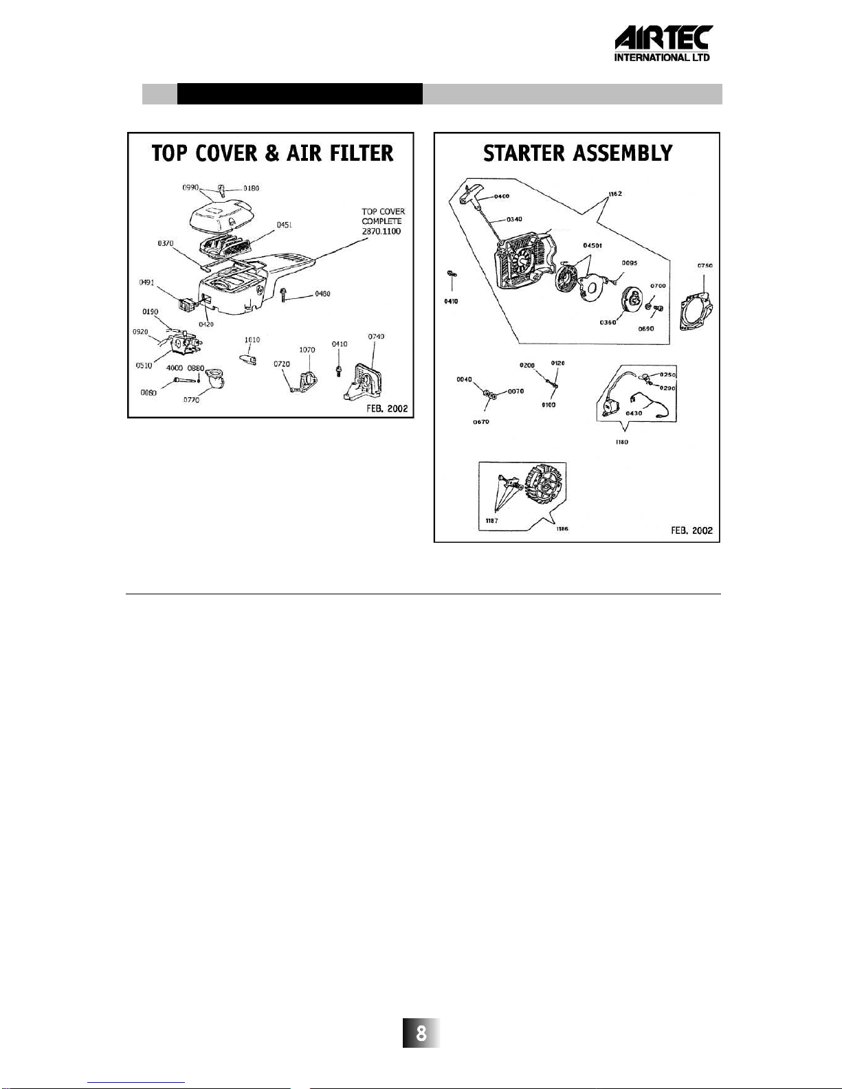
1. REPLACEAIRFILTER4003.0451
Unfasten two Screws 0180 on Filter Cover
0990 and lift off. Remove and replace Air
Filter.
2. REMOVINGTOPCOVER2870.1100
Loosen three Screws 0480. Push rubber air
intake 0770 through Top Cover. Remove wires
from On/Off Switch 0491 noting position for re-
connecting. Refit using Air Intake Tool Part
No. 4002 9005.
3. REPLACINGFUELPRIMER
ASSEMBLY4003.0810
Remove Screws 2303.0315 and take off Bulb
Protector 2650.1010 and pull Primer from
Motor.
Please note : for Primer re-connection connect
Pipe 1190 from Fuel Tank to "out" port and Pipe
0910 from the Carbrettor "in" port.
4. REPLACINGSTARTER
RECOILSPRING4003.04501
Follow procedure for replacing Pull Cord -
See 7.4 on Page 6.
With the pulley separated from Starter
Housing, remove the two Screws.
Remove old Spring Cassette and replace
with new one. Refit screws.
When refitting Starter Housing pull Starter
Cord to ensure it operates before tightening
Screws.
Please Note:
TheSpringintheCassetteCaseis
pre-tensioned. Always handle with care.
5. REMOVINGFLYWHEEL
4003.1186
Fit Piston Stop Tool 10.00022 into Cylinder
and remove Flywheel Nut 0040. Remove
Flywheel Ratchet Assembly1187. Using
Puller 10.00049 with Screws 10.00362 remove
Flywheel. Take care not to lose Key0220.
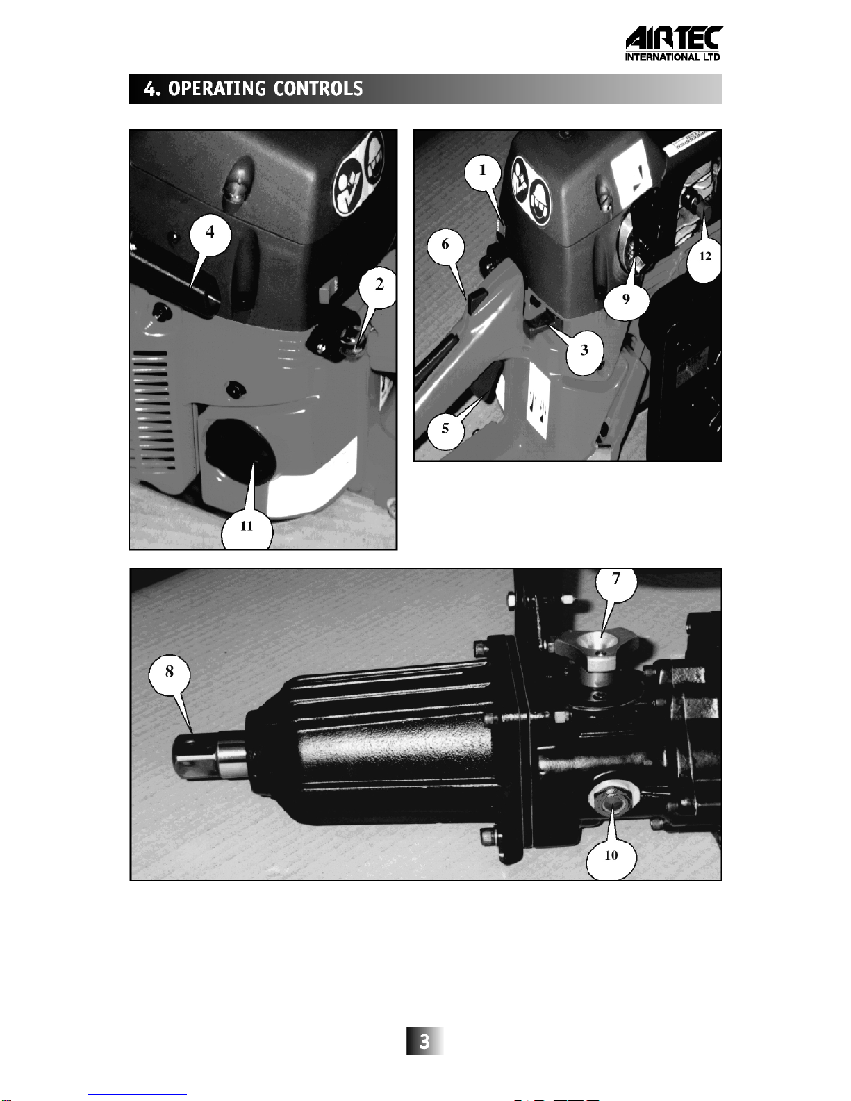
6. REMOVINGEXHAUSTGUARD8AND
MUFFLERASSEMBLY4003.0850
Remove five Screws 7 holding Exhaust
Guard and lift off. Unfasten two Screws 0640
on inside of Exhaust Box and remove it and
Gasket 0860 from Motor.
Ensure Motor/Muffler is warm when
re-fitting Screws
7. REMOVING THECARBURETTOR
4003.0510
RemovetwoScrews0080, Screw0720 andFuel
Pipes 0190 & 0920 from Carburettor making
sure to note re-connecting positions.
Disconnect Choke Linkage 0880 and Throttle
Linkage 1020 and remove Carburettor.
8. DISMANTLINGMOTORFROM
IMPACT UNIT
Remove Carrying Handle 97 and four Screws
24 holding Clutch Support Flange 18 to Engine
Flange 9. Pull apart.
9. REMOVINGCYLINDERANDPISTON
4003.1165
Remove three Screws 0410 holding Carburettor
Flange 0740 to Casing. Depress Spring Clip
0390 behind Carburettor Flange and pull from
Cylinder. Loosen four Screws 0630 holding
down Cylinder and lift off. Remove Spring Clip
4001 4200 from inside Piston and Gudgeon Pin
0800. Lift off Piston 1120. Check Piston Rings
0820 for wear and replace if necessary.
Rebuild in reverse order.
Please Note: If Clutch is to be removed
leave Cylinder and Piston in position until
after this is done.
10. REMOVINGCRANKCASE4003.1150
& 4003.1169 FROM FUEL TANK
4003.1045
Remove Screws 0110 to allow Crankcase to
be disconnected from Fuel Tank.
11. REMOVINGCRANKSHAFT 4003.0985
Remove seven Screws 4001.1100 from Clutch
side of Crankcase. Run Flywheel Nut 0040
onto Crankshaft 0985 until flush with the end.
Hold Crankcase tightly and using a soft faced
mallet tap against the Flywheel Nut until the
Casing splits.
Please Note: a) It is advisable to replace all Gaskets
and Seals when rebuilding Motor.
b) If Primer Bulb 0810 is burst
disconnect two Fuel Pipes 0910 and
1190 and plug the holes.
DO NOT CONNECT THE PIPES
TOGETHER Replace Primer Bulb
Assembly as soon as possible. (see
section 8.3)
7

TOPCOVER AND AIR FILTER STARTERASSEMBLY
Part. No. Description Part. No. Description
2870 1100 Top Cover Complete (See Note 4, Page 12 4003 0040 Nut
4000 0880 Washer (2) 4003 0070 Washer (50.00361)
4003 0080 Screw (2) 4003 0095 Screw (2)
4003 0180 Screw (2) 4003 0100 Washer (2)
4003 0190 Pipe 4003 0120 Washer (2) (60.00315)
4003 0370 Gasket 4003 0200 Screw
4003 0410 Screw (3) 4003 0250 Plug Cap
4003 0420 Lead 4003 0290 Spring
4003 0451 Air Filter 4003 0340 Recoil Starter Cord
4003 0480 Screw (3) 4003 0360 Pulley
4003 0491 On/Off Switch (See Note 2 Page 12 4003 0400 Handle
4003 0510 Carburettor (AT version) 4003 0410 Screw (4)
4003 0720 Screw 4003 0430 Lead
4003 0740 Carburettor Flange 4003 0670 Washer
4003 0770 Rubber Air Intake 4003 0690 Screw
4003 0920 Pipe 4003 0700 Washer
4003 0990 Air Filter Cover 4003 0750 Flange Cover
4003 1010 Screen Guide 4003 1162 Starter Assembly (See Note 11 Page 12)
4003 1070 Spacer 4003 1180 Coil Assembly
4003 1186 Flywheel Assembly (See Note 2 Page 12)
4003 1187 Flywheel Ratchet Assembly
4003 04501 Recoil Spring Assembly
9. MASTERMOTORPARTSLIST

CYLINDER & PISTON CARBURETTOR
Part. No.
Description
2650 0060 Throttle Stop (AT version)
2300 0520 Screw (5) (AT version) 4003 0000 Pin
2400 1050 Washer (5) (AT version) 4003 0010 Screw (33.00202)
4000 0378 Bearing (2) 4003 0020 Screw (33.00209)
4000 0809 Spark Plug 4003 0160 Screw (4) (50.00162)
4000 0885 Washer 4003 0170 Screw
4001 4200 Spring Clip (2) 4003 0260 Throttle
4001 4320 Seal 4003 0270 Ball
4003 0210 Seal 4003 0280 Spring
4003 0220 Key 4003 0300 Spring
4003 0390 Spring Ring 4003 0310 Spring (2)
4003 0580 Bearing 4003 0500 Shutter Disc
4003 0630 Screw (4) 4003 0520 Cover
4003 0640 Screw (2) 4003 0530 Screw
4003 0760 Manifold 4003 0540 Screw
4003 0800 Gudgeon Pin 4003 0610 Screw (2)
4003 0820 Piston Ring (2) 46mm dia 4003 0930 Shaft AssemblyThrottle
4003 0830 Gasket 4003 0940 Shaft AssemblyChoke
4003 0850 Muffler Assembly (AT version) 4003 0950 Cover
4003
0860
Gasket Insulator
4003
0970
Spring
4003 0885 * De-Compression Button(SeeNote1Page12) 4003 0980 Screw
4003 0985 Crankshaft 4003 1000 Walbro Carburettor Gasket Set
4003 1030 Muffler Cover 4003 1050 Walbro Carburettor Repair Kit
4003 1120 Piston Assy 46mm dia(SeeNote7Page12)
4003 1165 * CylinderAssembly46mmdia
(SeeNote1Page 12)
*Ordertogether
10. MASTERMOTORPARTSLIST

11. MASTERMOTORPARTSLIST
CRANKCASE& FUEL TANK
Part. No.
Description
135596 Screw M5 x 25
2303 0315 Screw (2) (AT version)
2650 1010 Bulb Protector
2800 0001 Fuel Tank Complete Assy.
3333 3334 Backing Plate
4000 0880 Washer (11)
4000 0378 Bearing (2)
4000 8770 Screw (4)
4001 1100 Screw (2)
4001 9100 Fuel Filter
4001 5462 Cap
4003 0090 Screw
4003 0230 Stud Bolt (2)
4003 0320 Throttle Lock
4003 0330 Spring
4003 0350 Rubber Mount (4)
4003 0380 Grommet
4003 0460 Breather
4003 0470 'O' Ring
4003 0550 Pin (2)
4003 0620 Screw (4)
4003 0710 Screw (3)
4003 0780 Grommet
4003 0810 Primer Assembly
4003 0840 Gasket
4003 0870 Rubber Mount (2)
4003 0880 Choke Linkage
4003 0910 Pipe Tubing
4003 0920 Pi pe
4003 1020 Throttle Linkage
4003 1040 Lever
4003
4003 1045
1060 Fuel Tank Only(See Note 5 Page 12 )
Handle Cover
4003 1090 Fuel Cap
4003 1140 Gasket Set
4003 1150 Half Crankcase
4003 1168 Half Crankcase
4003 1175 Stud Bolt
4003 1190 Pipe Tubing
10
1168
FEB 2005
1175

12. MASTERCONVERSIONKITPARTSLIST
11
DRWG
PART
DESCRIPTION
REF. NO.
1 2810.1030 Motor Complete
2 2570.0050 Cam with Shaft
3 2510.0030 Regulator Spring
4 035588 Torque Control Lever
5 135593 Screw
6 135597 Washer (5)
7 2300.0520 Screw (5)
8 2650.1400 Exhaust Guard
9 2600.1630 Motor Flange
10 135571 Washer (7)
11 135570 Washer (7)
12 135569 Lock Nut (3)
13 2332.0201 Bearing
14 2540.0130 Bearing Flange
15 4003.0600 Clutch Disc
16 4003.1110 Clutch Complete
16/2 4003.0050 Clutch Spring
17 2690.7710 Clutch Ring
18 2600.3130 Clutch Support Flange
19 2343.0420 Oil Seal
20 2332.0250 Bearing (2)
21 135553 Circlip
22 135552 Circlip
23 135513 Washer (19)
24 135515 Screw (9)
25 035514 Gasket
26 035554 Pin (2)
27 135508 Cir clip
28 2640.7000 Gear
97 2800.4030 Handle Complete
98 2620.5100 Handle
99 2310.2061 Lock Nut (2)
100 2400.2060 Washer (2)
101 4000.3290 Rubber Mount Washer (2)
102 5400227 Rubber Mount (4)
103 2650.2000 Bracket
104 5400563 Rubber Mount Washer (2)
105 2580.0080 Screw (2)
106 2305.0620 Screw (2)
CONVERSION KIT 2810.1004
TO CONVERT STANDARD MASTER 35
INTO NEW STYLE
Last Serial No. for STANDARD Master 35
ATD 00A44 approximately December 1999
First Serial No. for NEW Master 35
ATE 99A01
approximately January 2000

13. MASTERMOTORPARTSLISTNOTES
1. Cylinder 4003.1130 replaced by De-
Compression version 4003.1165 and
Button 4003.0885 from Serial No.
ATE00M01
2. Part Number Changes
Old Description New
2650.0050 Throttle Stop 2650.0060
4000.1620 Spark Plug 4000.0809
4001.5461 Cap 4001.5462
4003.0440 Ratchet Assy. 4003.1187
4003.0450 Air Filter 4003.0451
4003.0490 On/Off Switch 4003.0491
4003.0730 Crankshaft 4003.0985
4003.0790 Flywheel Assy. 4003.1186
4003.0890 Starter Housing 4003.1043 **
4003.1025 Screw 4003.0610
4003.1080 Starter Assy. 4003.1162
4003.1160
Half Crankcase
4003.1169
3. Top cover only 4003.1170 no longer available. (05.03.01).
4. Top Cover complete 2870.1100
comprises the following parts:-
Top Cover 4003.1170
On/Off Switch 4003.0491
Gasket 4003.0370
Cam with Shaft 2570.0050
Regulator Spring 2170.0030
Torque Control Lever 035588
Screw
135593
5. Fuel Tank only 4003.0900 replaced by 4003.1045.
6. Recoil Spring 4003.0030 now supplied as an Assembly 4003.04501
7. Piston Assembly 4003.1120. When ordering please advise the type e.g. A, B, C or D.
This can be found on top of the cylinder.
8. STANDARD MASTER 35 Impact Wrench can be converted into new style using Motor
Conversion Kit Part No. 2810.1004.
9. Stud Bolt 4003.1175
Replaces Stud Bolt 4003.0230 from Machine No. 02L044
10. Muffler Screw 2300.0520
Please ensure Motor Muffler is hot when fitting these. Tightening torque 9Nm
If tightened when cold Screws will not hold.
**
11. Starter Housing 4003.1043 no longer available 01/02/06. Order Starter Assembly
4003.1162.
12

14. DISMANTLING IMPACT UNIT (See Exploded Diagram Drawings on Page 16).
1. REMOVING CLUTCH SUPPORT
FLANGE 18
Remove Gear Selector 46 and empty oil
from Gearbox 30. Remove six Screws
holding Clutch Support Flange to Gearbox
and pull apart.
2. REMOVING CLUTCH 16 AND MOTOR
FLANGE 9
Remove Spark Plug 0060 and fit Piston Stop
Tool 10.00022. Turn Clutch Nut 16 in
clockwise direction. Loosen two Lock Nuts
12 holding Motor Flange to Motor and pull off
Flange.
To replace Motor Flange Bearing 13 press
out and replace. Assemble in reverse order.
3. REPLACING SEAL 19 & BEARINGS 20
IN CLUTCH SUPPORT FLANGE 18
Remove Circlip 21 and using a soft face
mallet tap out Clutch Ring 17. Remove
Circlip 22 and from the opposite side push
out Bearings 20. Remove Oil Seal 19 and
replace if necessary. Assemble in reverse
order.
4. DISMANTLING GEARBOX 29
Remove Circlip 27 and lift off Gear 28.
Remove Ring Flange 67 and check Bearings
66 & 69 and Oil Seal 68 for wear or damage.
Remove Bearing Shaft 42 and check.
Remove Circlip 31 and from the opposite
side tap out Selector Shaft 33. Using a 5mm
Screw extract Planet Pivot 39 by holding the
Screw Head in a vice and tap Gearbox with
a soft face mallet. Remove Planet Gear 38
and Spacer 36.
Please Note: The Planet Gear has a
chamfered edge which MUST be re-fitted
in the same way as before.
Take out Gear Cluster 41 and note
directions for re-building. Assemble in
reverse order.
5. DISMANTLING HAMMER COMPLETE
78
Place complete Hammer length ways in a
vice with one hole uppermost. Carefully
tighten vice until Steel Ball 76 drops out of
lower hole (a short blast of air will assist this
operation). Loosen vice and turn Hammer 83
through 180
o
degrees and repeat previous
instruction to allow second ball to be
removed. Slowly loosen vice again.
Hammer Casing 83 and Catch 71 can now
be separated. Remove Shaft 75, Spring 77
and Bearing 74 and inspect for wear.
Using Circlip Pliers remove Seeger Rings 79
from Hammer Casing. Tap off Steel Ring 80
with a punch, Knock out four Steel Plugs 82
from inside to allow Cam 81 to be removed
from Hammer Casing.
Please Note: Always renew the Steel
Plugs before rebuilding.
Inspect Anvil 84 and Hammer 83 striking
faces for wear or damage. These are critical
areas which will affect the Wrench's
performance.
Inspect all parts for wear or damage and
replace, grease up and re-build in reverse
order.
Fit new Gasket 85 and refit Nose Casing 86.
Please Note: It is advisable to replace
Seals, 'O' Rings and Gaskets when re-
building the Impact Unit.
13

15. MASTERIMPACT PARTS LIST
Note : Fastener torques shown on Page 17
14


MOTOR & GEARBOX PARTS LIST
DRG. PART DESCRIPTION DRG. PART DESCRIPTION DRG. PART DESCRIPTION
REF NO. REF. NO. REF. NO.
1 2810.1030 Motor Complete 24 135515 Screw 48 135513 Washer
2 2570.0050 Cam with Shaft 25 035514 Gasket 49 035107 Gear Change Knob
3 2510.0030 Regulator Spring 26 035554 Pin (2) 50 135110 Bevel Washer
4 035588 Torque Control Lever 27 135508 Circlip 51 035111 Gear Flange
5 135593 Screw 28 2640.7000 Gear 52 035523 Spring
6 135597 Washer (5) 29 035305 Gasket complete 53 135114 ‘O’ Ring
7 2300.0520 Screw (5) 30 035105 Gearbox Casing c/w Bronze Bush 34 54 104051 Ball
8 2650.1400 Exhaust Guard 31 135516 Circlip 55 035112 Gear Selector
9 2600.1630 Motor Flange 32 102020 Bearing 56 035554 Pin
10 135571 Washer (7) 33 035119 Selector Shaft 57 035113 Selector Pin
11 135570 Washer (7) 34 035106 Bronze Bush 58 135116 Screw (3)
12 135569 Lock Nut (3) 35 135520 Oil Plug & Felt Washer 59 135597 Washer (7)
13 2332.0201 Bearing 36 035550 Spacer 60 135513 Washer (19)
14 2540.0130 Bearing Flange 37 0335548 Bronze Bush 61 135515 Screw (9)
15 4003.0600 Clutch Disc 38 035551 Planet Gear c/w Bronze Bush 37 62 135569 Lock Nut
16 4003.1110 Clutch Complete 39 035549 Planet Pivot 63 135570 Spring Washer (3)
16/2 4003.0050 Clutch Spring 40 103020 Bearing 64 135571 Washer
17 2690.7710 Clutch Ring 41 035104 Gear Cluster 107 2890.1050 Gasket Kit
18 2600.3130 Clutch Support Flange 42 035102 Bearing Shaft c/w Bush 43 109 2700.0220 Washer
19 2343.0420 Oil Seal 43 035103 Bush 110 2304.0520 Screw
20 2332.0250 Bearing (2) 44 035560 Gasket 111 2700.0200 Threaded Plate
21 135553 Circlip 45 035115 Gasket 112 2650.1050 Fuel Tank Wear Plate
22 135552 Circlip 46 035304 Gear Selector Complete 113 2400.2060 Washer
23 135513 Washer (19) 47 135506 Screw 114 2305.0620 Screw
15
Other manuals for MASTER 35
2
Table of contents
Other Air TEc Impact Driver manuals