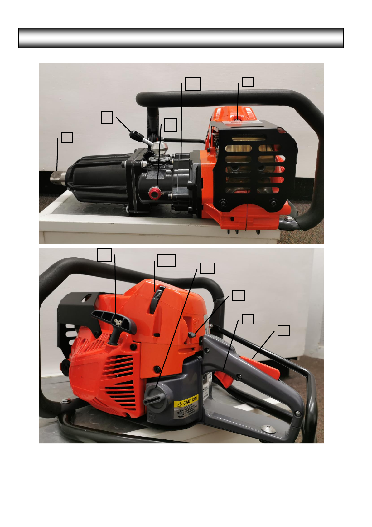
New Master 35 Petrol/Gasoline Impact Wrench
BEFORE using the Impact Wrench read these safety instructions CAREFULLY and ensure you fully
UNDERSTAND them. DO NOT allow untrained personnel to use the Wrench.
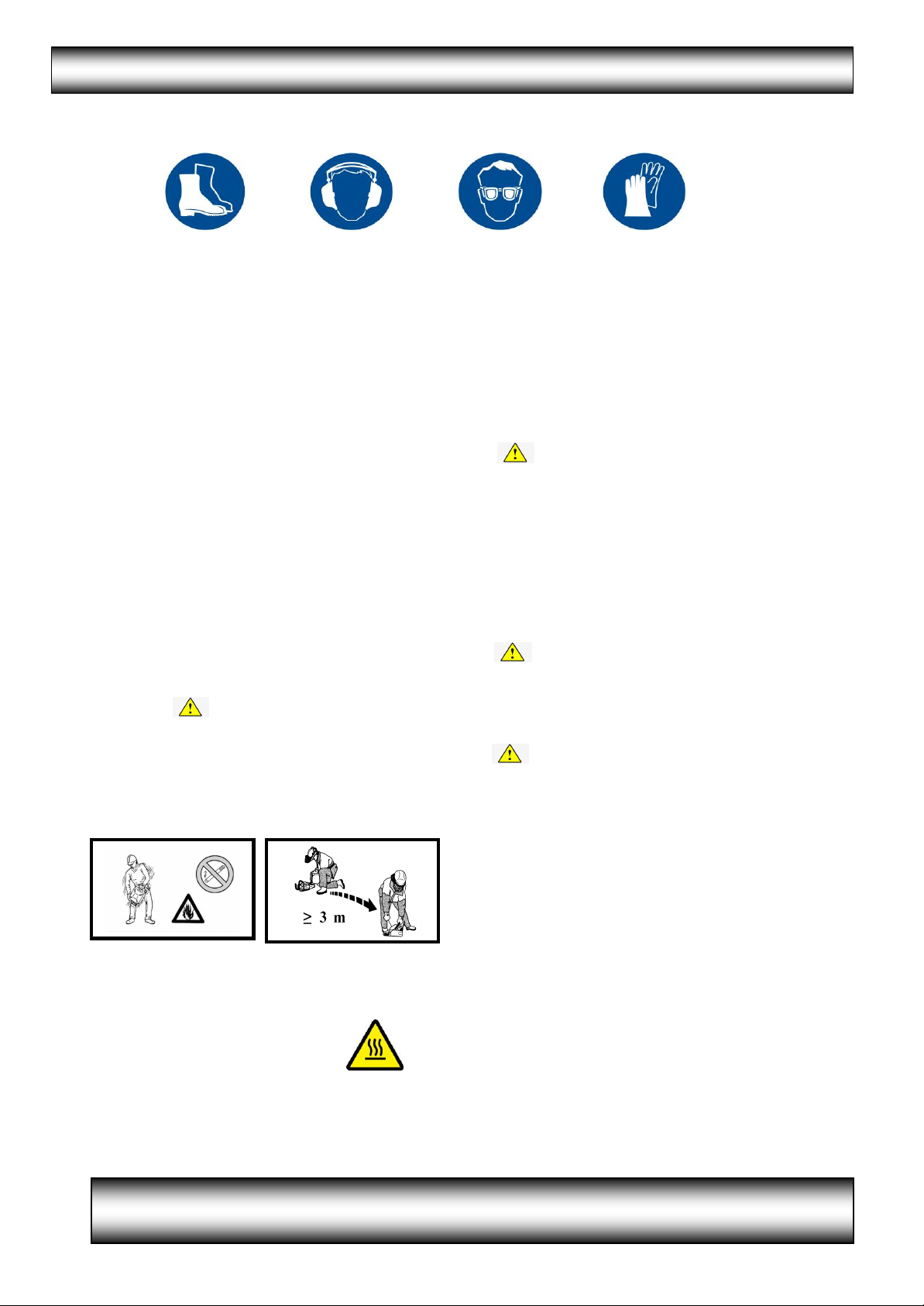
1. Wear suitable PROTECTIVE CLOTHING, safety
boots, goggles, gloves and ear protection
according to Company rules, working
conditions or Government/State Legislation.
2. The effect of vibration exposure can be
REDUCED by following a number of simple
rules :-
a) Always wear protective gloves and keep
hands warm and dry.
b) Ensure Wrench is properly maintained.
c) Do not use worn Sockets and ensure
Wrench Anvil is replaced when worn.
Use of our NO GO GAUGE allows quick
and easy checks on Socket Square
Drive and Anvil wear.
d) Share the workload whenever possible.
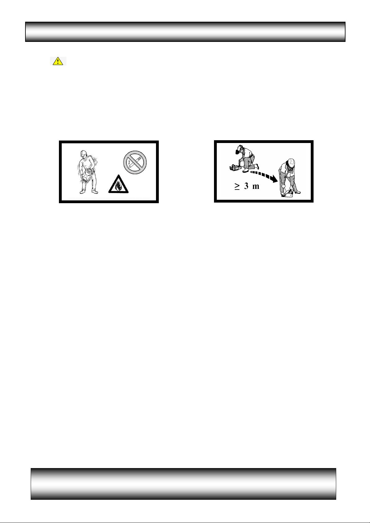
3. FILL the fuel tank carefully BEFORE starting the
Wrench in a well ventilated area and avoid
spillage. Use the Fuel Funnel provided or a
Safety Fuel Can. DO NOT fill or add oil while the
Motor is running. Allow machine to cool before
re-fueling, DO NOT over fill, allow for
fuel expansion. Keep well away from naked
flames or equipment which generates sparks
e.g Rail Saw or Rail Grinder. Do not leave the
mixture in the fuel tank for any prolonged
period of time.
4. The exhaust is fitted with a Catalytic
Converter to reduce emission levels to meet
EUR5 and EPA 3 Standards.
It will become HOT during and
after use.
Please AVOID direct contact.
5. Know where the controls are and how to
use them and be able to STOP the Wrench
quickly in an emergency.
6. Do Not Operate in confined spaces because of
the danger of Carbon Monoxide being present.
7. Remove FUEL FILLER CAP CAREFULLY as
pressure can build up in the tank. This is very
important in warm weather, if the Wrench has
been left in an exposed area or after
prolonged periods of use.
8. Do not wear hanging jewellery, a tie or
loose or torn clothing.
9. Take up a FIRM footing and maintain a balanced
body position
10.Check pull cord is not frayed or worn.
11.Use only IMPACT QUALITY Sockets and
Accessories
HAND Sockets must NEVER be used
12.Use Rubber Rings and Steel Pins or other
suitable retaining devices to retain the
Socket or Accessory onto the Square Drive.
DO NOT use twigs, wire, nails or plastic
straps.
13.Set the GEAR CONTROL in NEUTRAL before
starting.
14.Check the Wrench for damage regularly.
Ensure fasteners are tight at all times.
A poorly maintained Wrench will be inefficient
and produce extra noise and vibration
15.Switch OFF ENGINE BEFORE transporting
the Wrench to another location.
16.Take CARE when LIFTING or carrying the
Wrench - weight with fuel and excluding
accessory approximately 18.5Kgs (40 ¾ lbs)
17.The engine has a break in period of 5 to 8
hours. During this time the engine may emit
some smoke.