Aircalo CASSETTE BALI Manual

INSTALLATION AND
MAINTENANCE
MANUAL
CASSETTE
BALI

1
1.GENERALITES .............................................................................................................................................. 1
2.PRESENTATION ........................................................................................................................................... 3
3.INSTALLATION ............................................................................................................................................. 3
Choice of the place ............................................................................................................................................ 3
Implantation ........................................................................................................................................................ 3
Reception – Storage .......................................................................................................................................... 3
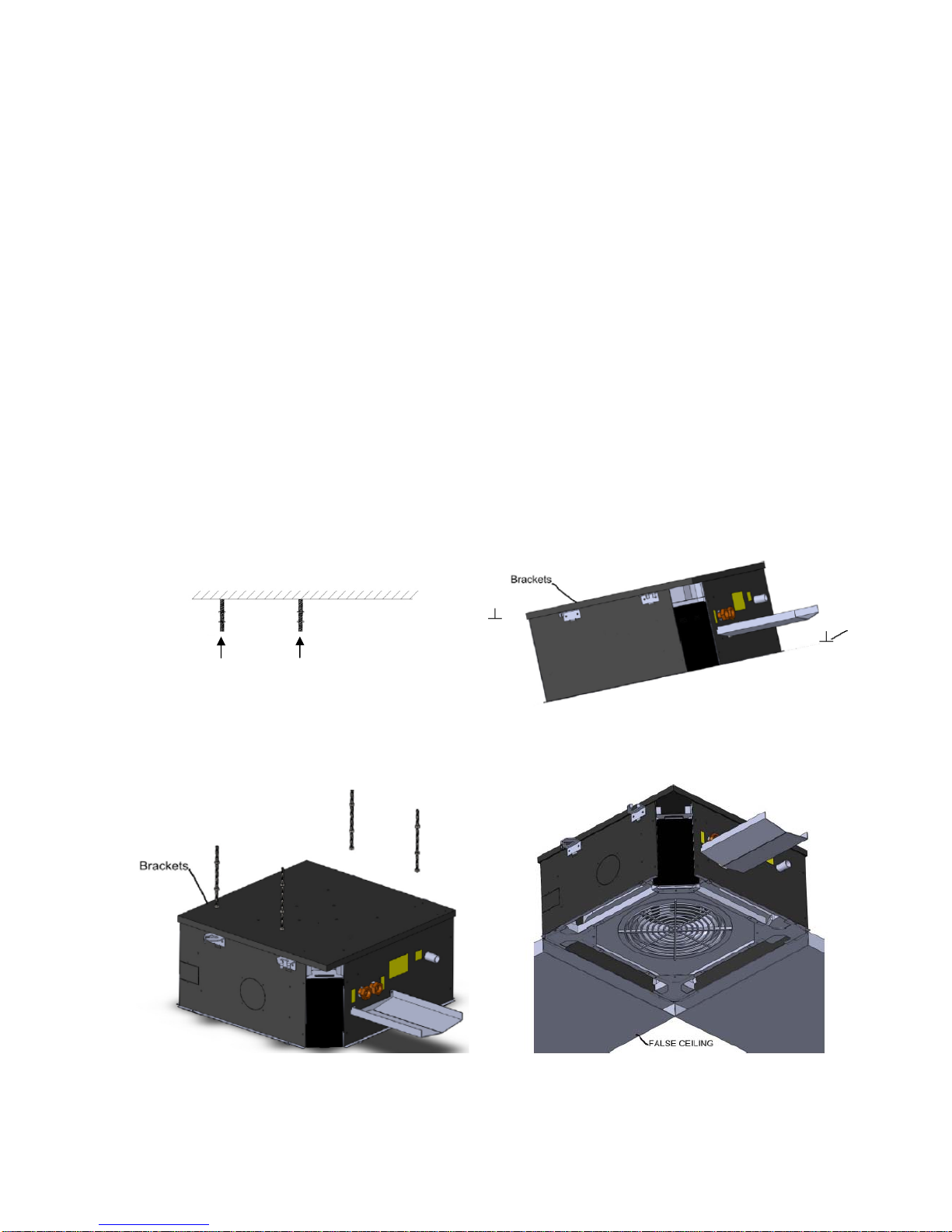
Fixation .............................................................................................................................................................. 3
Condensate drain .............................................................................................................................................. 7
4.FRESH AIR CONNECTIONS ....................................................................................................................... 8
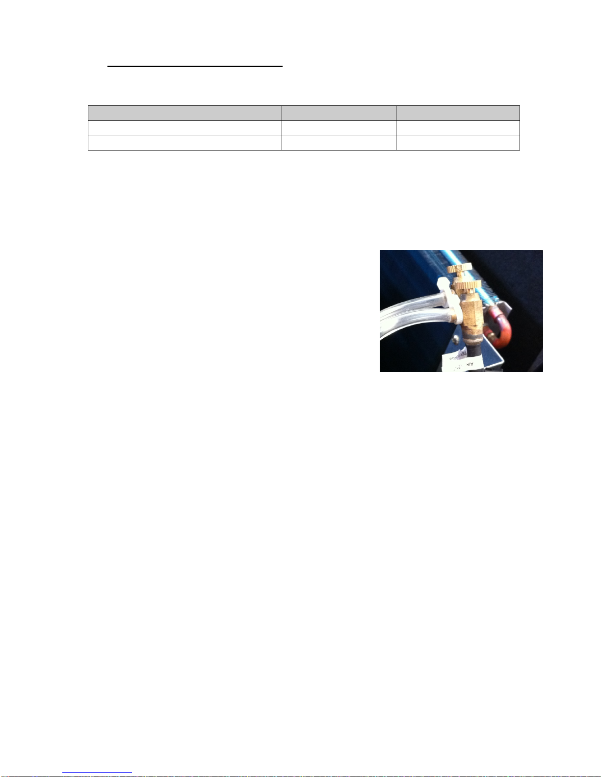
5.HYDRAULIC CONNECTIONS ...................................................................................................................... 9
Instructions ......................................................................................................................................................... 9
Control valves .................................................................................................................................................... 9
External Drain Pan ............................................................................................................................................ 11
6.ELECTRIC CONNECTIONS ........................................................................................................................ 12
Motor power ...................................................................................................................................................... 12
Electric power auxiliary heating resistor ........................................................................................................... 12
Electrical connections (4 Pipes) ........................................................................................................................ 13
Electrical connections (2 Pipes + Electrical heater) .......................................................................................... 14
7.BOX CONTROL ......................................................................................................................................... 195
Description ........................................................................................................................................................ 15
Control logic ...................................................................................................................................................... 16
8. LED INDICATION AND ERROR DESCRIPTION ....................................................................................... 17
9.SPEED CONTROL BOX .............................................................................................................................. 18
10.DIMENSIONS AND WEIGHT ...................................................................................................................... 19
11.START-UP ................................................................................................................................................... 21
12.MAINTENANCE ......................................................................................................................................... 262
Removing the internal components .................................................................................................................. 22
Fan motor replacement .................................................................................................................................... 23
Replacement control box .................................................................................................................................. 23
Condensate pump replacement ........................................................................................................................ 24
Replacing electrical resistance ......................................................................................................................... 25
Long shutdown periods ..................................................................................................................................... 25
User guide ........................................................................................................................................................ 25
13.SPARE PARTS .......................................................................................................................................... 266
To get all the air flow and acoustic performances, refer to the general catalogue and/or the BALI datasheet
(available on www.aircalo.fr)

2
1. GENERALITES
CAUTION: before any intervention on the system and before handling any intern component, cut the power of the
main circuit-breaker.
Read attentively this manual before starting the installation
The unit is in conformity with the Low Voltage Directive (CEE/73/23) and electromagnetic compatibility
(CEE/89/336).
Confide the installation to a qualified installer.
The maintenance must be made only by qualified personnel.
Respect safety requirements of national standards. In particular, check that you dispose of a connection
on the ground with an adequate size.
Check that the tension and the frequency of the power supply is like the ones necessary at the unit
which will be installed.
Eventually, take into account of others devices connected up at the same electric circuit.
Make sure that the safety requirements of national standards have been respected over the power
supply circuit
Use this unit only as a part of registered applications: they do not have to be used in a laundry room or
any other local with steam ironing.
It should be avoiding the use of Cassettes in an atmosphere that contains oil vapors or corrosive.
It is recommended to disinfect once by year, condensate drain pan to avoid the development and
spreading of legionella.
Keep the device away from frost.
Do not install or use damaged devices.
The manufacturer declines any responsibility for damage caused by the modification or mistake in
electric connections or hydraulic connections.
Failing to follow the electric security rules can cause a risk of fire in the case of an electric short.
In case of an unusual functioning, turn off the unit, remove the electricity supply and contact specialized
personnel.
Unless particular conditions, Aircalo gives one year parts warranty against defects in conception or
production. Are excluded defects of installation and use and also wearing parts and environment
condition which damage the smooth functioning of the device that would have not be specified in the
order.
Failing to follow the manufacturer instructions concerning the installation or the use of the unit in
conditions that exceed functioning limits indicated in this manual can lead to the loss of the unit warranty.

3
2. PRESENTATION
Bali cassettes are equipped with EC fans. They are available in section:
- 600 x 600 mm
- 900 x 900 mm
3. INSTALLATION
Choice of the place
Avoid the following locations:
Exposure to sunbeam
Areas near sources of heat.
Humid locations and places where water may penetrate into the unit.
Places where curtains or furniture can disturb a good circulation of the air.
Location advised:
A place without obstacle that can cause an unequal distribution or return of the air.
Consider a location where the installation will be easier.
Allow required clearances.
Look for a place into the room that will guarantee a good distribution of the air.
It could be easier to connect condensate drain pipe through the appropriated pipework.
Implantation
It is recommended to position the unit in the center of the room to ensure a good air distribution.
Caution: the power capacity of installed units must be defined following the thermal balance and the
acoustic of the locals.
Check that the panels from the false ceiling can be dismounted in order to get enough space for
maintenance. All of the hydraulic and electric arrangements are put on a same lateral face.
Do not put the Cassettes on false ceilings which are not horizontals (because it caused water runoff).
Reception - Storage
Check the conformity of goods delivered according to the order. Read and control the instructions given
by the identification plate.
In the case of lack or damages, it must be done reserves on the delivery bill to the carrier. Then, confirm
this with a registered letter over 48 hours.
Storage the equipment in a clean, dry place, protected from shocks, vibration and temperature
fluctuation and at a relative humidity level of less than 90%. The period of storage should not exceed 1
year.
Proceed with the unpacking of the device using the protections of accident prevention which are
required. Recycle packaging in accordance with local laws regarding waste.
It is recommended to bring the unit as close as possible to its definitive location before to unpack it.

4
Fitting
Standard units
Use a lift truck to facilitate the installation of the ceiling unit.
To avoid damaging the slab, disassemble and store waiting for the end of the installation:
- Remove the intake grille.
- Remove the screws of the slab.
- Remove the panel of the unit.
• Fit the 4 tie rods (recommended diameter M8) ceiling following the spacings of the cassette mounting ears to
rise. (The ears are formed with oblong holes to permit a final adjustment.)
485× 863: Suspension Bolts
850× 850: Dimensions for opening
280 x 622: Suspension Bolts
600 x 600 : Dimensions for opening
BALI 60 BALI 90
Table of contents
Other Aircalo Air Conditioner manuals
Popular Air Conditioner manuals by other brands

Fujitsu
Fujitsu ASYG 09 LLCA installation manual

York
York HVHC 07-12DS Installation & owner's manual

Carrier
Carrier Fan Coil 42B Installation, operation and maintenance manual

intensity
intensity IDUFCI60KC-3 installation manual

Frigidaire
Frigidaire FAC064K7A2 Factory parts catalog

Sanyo
Sanyo KS2432 instruction manual

Mitsubishi Electric
Mitsubishi Electric PUHZ-RP50VHA4 Service manual

Panasonic
Panasonic CS-S18HKQ Service manual

Panasonic
Panasonic CS-E15NKE3 operating instructions

Gree
Gree GWH18TC-K3DNA1B/I Service manual

Friedrich
Friedrich ZoneAire Compact P08SA owner's manual

Daikin
Daikin R32 Split Series installation manual