Aircraft In Miniature HW72-03-001 User manual

Historic Wings
History, Notes and
Assembly Instructions
1:72 Metal Kit of the
1909
Santos Dumont Demoiselle
© Copyright unknown

History
Alberto Santos-Dumont was born in Brazil on July 20, 1873, the young Brazilian was small in
stature and always distinguished as a smart dresser with a high collar and a Panama hat. At eighteen
years of age he travelled to Paris to pursue his interests in mechanics and aeronautics. His balloons
were followed by the 14 bis (also available as a Historic Wings kit) and finally the subject of this
model, the Demoiselle.
The Santos-Dumont Demoiselle ("Damselfly") first flew in 1907, an elegant monoplane in
which Santos-Dumont completed the first flight between two cities, from Saint-Cyr to Buc, at record
speed of 95 Km/h. It was also the first aircraft to be produced in quantity in a factory. Four versions
were built, which were No. 19, No. 20, No. 21 and No. 22. There were many variations of landing
gear and two engine positions during its life.
It was after a crash in a Demoiselle that Santos Dumont gave up flying for good in 1910.
Introduction
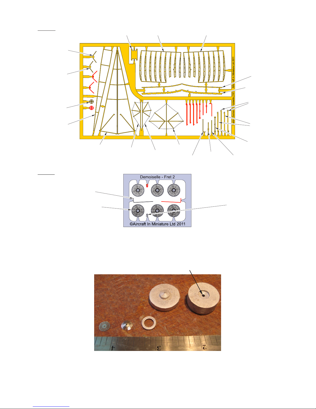
This Historic Wings kit is made from etched brass for the main structure, with cast metal and
etched nickel silver detail parts. The flying surfaces can be covered with the Litespan film supplied,
although many modellers may prefer to leave the structure uncovered to show the details.
Brass components can be soldered together, or joined with cyanoacrylate (super glue - CA
adhesive) or 5-minute epoxy (epoxy adhesive). If you have the skills and equipment we recommend
soldering for the brass parts.
To remove parts from the etched fret, you can use a pair of side cutters, or put the fret on a ceramic
tile, and press down on each attaching tab with a sharp knife. If you use the ‘knife & tile’ option, put
the attaching tab with the half-etched side of the tab face down. Whichever method is used, it may
necessary to remove the burr of the attachment tab with a needle file afterwards.
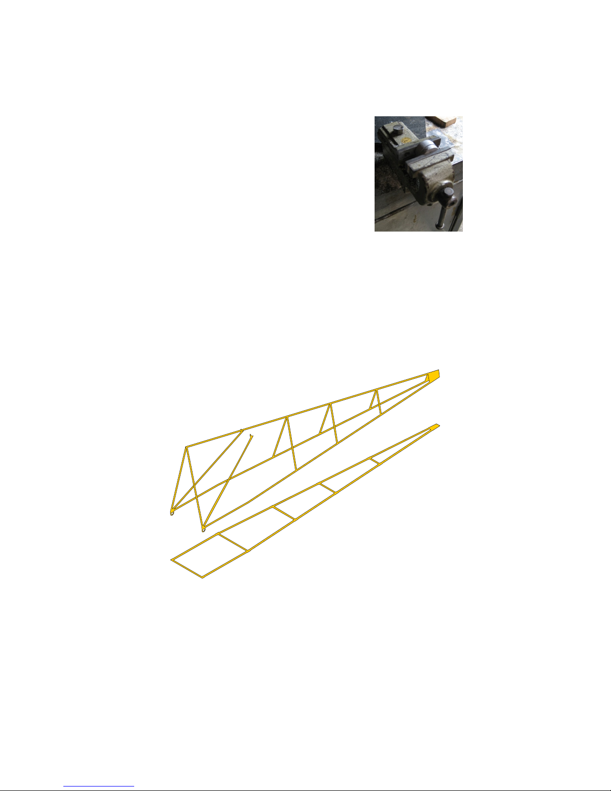
The wings are etched with integral ribs. Hold the leading or trailing edge in a vice or clamp, and
then hold each rib in turn with a pair of fine flat-nosed pliers, and twist that rib through 90 degrees.
When all th e ribs have been turned, clamp the trailing edge, and do the process again.
Where etched parts are joined with two inter-locking slots it may be necessary to enlarge a slot
with a needle file. This is because photo-etching is not an exact process, and sometimes the etching is
slightly uneven across a sheet.
Cast Metal Etched metal
Engine . . . . . . . . . . . . . . . . . . . . . . . . . 1 off Fret 1 - brass . . . . . . . . . . . . . . . . . . . . 1 off
Form tool - female . . . . . . . . . . . . . . . . 1 off Fret 2 - nickel silver . . . . . . . . . . . . . . 1 off
Form tool - male . . . . . . . . . . . . . . . . . 1 off Wire (for axle). . . . . . . . . . . . . . . . 1 length
Fuel tank . . . . . . . . . . . . . . . . . . . . . . . 1 off
Figure - Alberto Santos Dumont . . . . . 1 off Miscellaneous
Main wheel tyre. . . . . . . . . . . . . . . . . . 2 off
Propeller . . . . . . . . . . . . . . . . . . . . . . . 1 off Instructions . . . . . . . . . . . . . . . . . . . . . 1 set
Parts List

Fret 1
A Drill a 1/16”/1.5mm diameter hole through the centre of the female form tool
as shown in Figure 1 below. This is to let you push the spokes out of the
form tool after they have been formed into a cone.
Figure 1
B Remove four spoke discs from the fret and remove any burrs from the
attachment tabs (the kit includes four spare discs).
Fret 2
1 ASSEMBLE THE SPOKED WHEELS
CONTROL
WHEEL
FRONT
FUEL TANK
SUPPORT
REAR
FUEL TANK
SUPPORT
SKID STRUT
TAIL
LANDING GEAR
STIRRUP
FUSELAGE
LOWER
SECTION
FUSELAGE
UPPER SECTION UPPER FIN
LOWER FIN TAILPLANE
FRONT SPAR
RIGHT WING
REAR SPAR
INNER
STRUTS
OUTER
STRUTS
CONTROL
COLUMN
LEFT WINGSEAT
DRILL HOLE IN FORM TOOL HERE
MAIN WHEEL SPOKE DISC
FUEL PIPE
(1 used, 1 spare)
Spare and unused parts
are shown in red.
FUEL TANK SUMP
(1 used, 1 spare)

C Form each spoke disc.
(1) Put each disc into the cavity in the female form tool.
(2) Put the male form tool into the cavity and press the disc into a cone. Figure 2
shows a vice being used to compress the form tool.
NOTE: These photographs show typical wheels,
spoke discs and tyres. They are NOT
specific to this kit.
Figure 2
(3) Remove the form tool from the vice and remove the formed disc of spokes.
(4) Do steps 1 C (1) thru 1 C (3) again for each of the spoke discs.
(see Figure 3)
A Remove the fuselage upper and lower sections from the fret and remove any burrs from
the attachment tabs.
B Fold the fuselage upper section into a ‘V’ shape, with a width equal to the fuselage lower
section. Note - there are fold lines etched on the inner face of the fuselage upper section.
C Attach the fuselage upper section to the fuselage lower section.
Figure 3
(see Figure 4)
A Remove the left and right wings and the front and rear spars from the fret and remove any
burrs from the attachment tags.
B Twist all the ribs on each wing through 90°.
C Engage the slots in the front and rear spars in the slots in the ribs of the right wing then bond
the wing spars in place.
D Put the rear spar through the fuselage structure. Engage the slots in the front and rear spars
in the slots in the ribs of the left wing then bond the wing spars to the ribs of the left wing.
2 ASSEMBLE THE FUSELAGE PRIMARY STRUCTURE
3 WING ASSEMBLY

E Attach the front spar to the front of the fuselage structure.
F Attach the rear spar to the top of the angled struts of the fuselage structure. Fold
these struts outwards as necessary (Refer to the front view on the 3-view drawing.
Figure 4
A Assemble the tailplane (see Figure 5, Detail A).
(1) Remove the tailplane and the upper and lower fins from the fret and
remove any burrs from the attachment tags.
(2) Tin the mating faces of the upper and lower fins and the tailplane.
(3) Attach the upper fin to the tailplane.
(4) Attach the lower fin to the tailplane.
B Assemble the main landing gear (see Figure 5, Detail A).
(1) Make the axle from the wire supplied,.
(2) Attach one wheel to the axle with approximate 1 mm projecting from the
hub of the wheel.
Figure 5
4 TAIL ASSEMBLY AND LANDING GEAR
ATTACH ANGLED STRUTS
TO REAR SPAR
ATTACH FRONT SPAR TO
FUSELAGE STRUCTURE
OUTER (LONGER)
LANDING GEAR STRUTS
INNER (SHORTER)
LANDING GEAR
STRUTS
SKID
TAIL
LANDING GEAR
STIRRUP
A
C
B
1mm/0.040"

SLOTS IN FUEL TANK
FOR SUPPORTS
FUEL TANK
REAR FUEL TANK
SUPPORT
(3) Put the axle through the holes in the lugs on the airframe (enlarge these
holes if necessary) and put the other wheel on to the axle.
(4) Trim the axle to length, so that there is approximate 1 mm projecting from
the hub of the other wheel.
(5) Attach the inner and outer landing gear struts. Put the lower end of each
strut on the axle and attach the upper end to the front spar against the
lugs on the spar.
C Assemble the tail landing gear (see Figure 5, Detail C).
(1) Fold the tail landing gear stirrup (stirrup) as shown.
(2) Make the axle from the wire supplied.
(3) Put the axle through the holes in the stirrup and wheel and bond the axle
in position.
(4) Attach the top of the stirrup to the underside of the fuselage structure.
(5) Attach the skid to the top longeron of the fuselage structure.
Figure 6
(see Figure 6)
A Fuel tank assembly:
(1) Cut two slots in the cast metal fuel tank for the two supports.
(2) Attach the supports to the fuel tank.
(3) Attach the fuel tank sump (an etched nickel silver part) to the underside of the
fuel tank.
(4) Attach the supports to the top of the wing. If you intend to cover the wing with
Litespan film, attach this assembly after the wing is covered.
B Curve the seat as shown, then attach it to the fuselage structure.
C Attach the control wheel to the left angled strut.
5 FINAL ASSEMBLY
FRONT FUEL TANK
SUPPORT
CONTROL
COLUMN
CONTROL
WHEEL
SEAT
FUEL TANK
SUMP
(nickel silver part)
FUEL PIPE
(nickel silver part)

D Fold the small lugs on the control column through 90°, then attach it to the right lower
longeron of the fuselage structure.
E Attach the fuel pipe (an etched nickel silver part) to the underside of the fuel tank
and to the rear of the engine
F Attach the engine to the front of the fuselage structure
G Attach the propeller to the engine.
A If the airframe is to be painted, do it at this stage in the assembly. Paint the structure
to resemble a light to medium brown wood. If the model is to be covered with
Litespan film, do not paint those areas where adhesive will be applied.
B If the model is to be covered with Litespan film (the film), cover the fuselage and
flying surfaces now. For each area:
(1) Cut a piece of the film which is larger than the panel.
(2) Apply a continuous layer of cyanoacrylate adhesive (superglue) to the
structures where the film will be attached.
(3) Attach the edge of the piece of film to one long edge of the bay and press it
down so that it is smooth, and without creases.
(4) When the superglue has attached the film securely, apply more superglue
to the other three sides of that bay.
(5) Pull the film smooth and attach the other three sides of the panel of film, so
that it is smooth and not slack.
(6) When the film is securely attached, use a sharp blade to trim off the
excess film.
(7) Do this procedure again for all the other panels to be covered.
A Add rigging if desired as shown in the 3 view drawing. We have found black
monofilament to give good results.
6 AIRFRAME COVERING AND PAINTING
7 RIGGING

Historic Wings
of 1909
Kit HW72-03-001
Santos Dumont Demoisiselle
Aircraft In Miniature Ltd © 2011
Initial Issue: 28th February 2011

NOTES
© Aircraft In Miniature Ltd 2011 - Initial Issue - 28th February 2011
The manufacturers reserve the right to alter parts; add to, or delete parts without prior notification
in the interests of quality control, production, or product improvement.
This kit is manufactured in the United Kingdom by
Aircraft In Miniature Limited
19, Watling Street, Nuneaton, Warwickshire, CV11 6JJ, England
Email: [email protected] - Web site: www.aim72.co.uk
Table of contents
Popular Toy manuals by other brands

Nerf
Nerf RIVAL NEMESIS MXVII-10K quick start guide

Carl Goldberg Products
Carl Goldberg Products skylane 62 arf instruction manual

LEGO
LEGO Bionicle 70787 Building instructions

Carrera RC
Carrera RC Race Catamaran manual

Marvel
Marvel Avengers owner's manual

ROBBE
ROBBE Cloud Dancer Assembly and operating instructions