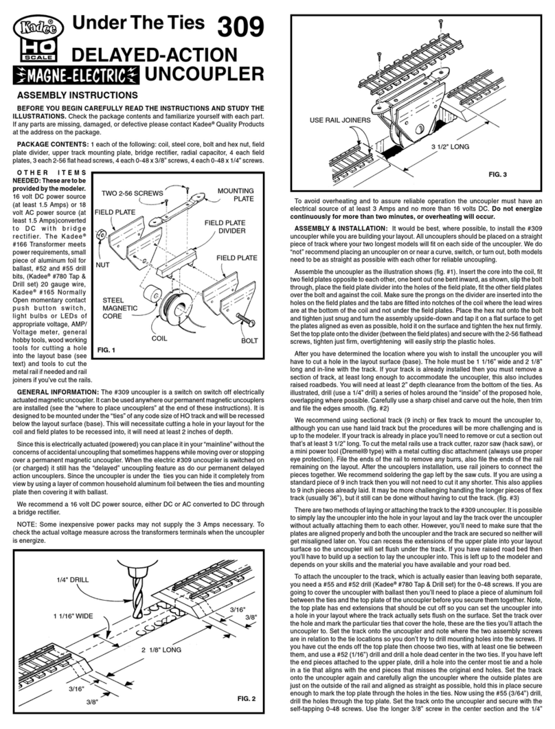
COVER
LOWERMOUNTING
PLATE
WITHBLAST
FIG.
4
5.
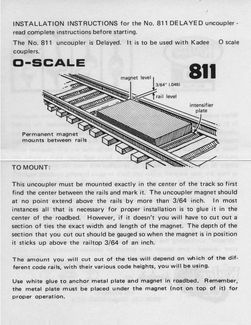
After
all
partshavebeenprepared,assemble
in
sequence
as
illustrated
in
Fig.
3.
Install
metalrailjoiners
atthe
ends
ofthe
rails
onthe
layout,pushthem
asfar
back
as
they'll
go.
Loweruncouplerassemblyintoplace(Fig.
3)and
pull
rail
joinersoverrailjoints.
6.Ifyou
haveinstalleduncoupler
on
roadbed,fill
the
gapsbetweenlowertrackmountingplate
and
layoutbasewithsections
of
roadbedtrimmed
to
fit.
Youmay
wish
toadd
someglue
to
thesesections
for
rigidity.
Ifyou
have
installed
uncouplerdirectly
to
layoutbase,
youmay
wish
to
spike
or
gluelowertrackplatedown
for
strength.Now,coverplatewithballastglued
in
place
withwhiteglue.
See
Fig.4.
ASSEMBLY
MODIFICATIONS:
Althoughthisuncoupler
is
designed,
asis,foruse
with
the
largerrailsizes,
itcanbe
modified
to
be
compatiblewithsmallerrail-evendown
to
code
40
size.This
is
accomplished,
in
simple
terms,
by
lowering
the
fieldplate/coreassembly
and
thinningdown
the
uppertrackplate
so
thatthey
are
evenwith
the
height
ofthe
rail.
1.
Assembleuncouplercompletelyminuslowertrackmountingplate
and
track.
Be
sure
and
use
the
included.010"thickwashers
as
shown
in
Figs.
1and3.
2.Add
extrafiberwashers(notincluded)between
the
uppertrackmountingplate
andthe
field
platedivider.
The
thickness
of
thesewashers
canbe
determined
by
subtracting
the
height
of
the
rail
youare
usingfrom
the
thickness
ofthe
uppertrackmountingplateends.
For
example,
theendofthe
upper trackplate
is
.055"thick
and
let's
saythe
rail
you
want
to
use
is
code
40
(.040")high.055"minus.040"equals.015".
Use
washer(s)equal
to
.015"thick.
3.
Afterassembly,notethat
thetopofthe
fieldplates
isnow
lowerthan
the
ends
ofthe
upper
track
plate.
Take
a
sandingblock,firstwithcoarsesandpaper,
and
slowlysanddownthese
ends
until
almost
evenwith
thetopofthe
fieldplates.Finishsandingdownevenusing
a
fine
grit
sandpaper(Fig.
A.)
COUNTER
SINK
WITH
#20
DRILL
FIG.
B
4.
Finishmodification
by
taking
a #20
drill
and
countersinking
theend
holes
inthe
mounting
plate
as
shown
in
Fig.
B.
Twistdrillslowly
by
handusing
a
shavingactionratherthancutting
action
to
preventgoing
alltheway
thru
the
hole.
WIRING:
After
installinguncoupler
inthe
track,it'stime
for
hooking
itup
electrically
for
use.
You
will
have
to
wire
the
uncouplercoil
totheDC
side
ofa
powerpackthru
a
pushbuttonswitch(not
included)
the
Kadee#165(N.O)normallyopenpushbuttonswitches
are
recommended,
see
Fig.
X.The
pushbuttonswitchneeds
tobea
singlepole,singlethrow(SPST)momentary
contacttype
and
should
be
able
to
handle
at
least
3
amp,8-12volts
DCthe
Kadee#165meet
the
requirements.
For
additionalinformation,
refer
to
Kalmbachbook"How
to
Wire
Your
Model
Railroad"
by
LinnWestcott.Pushbuttonswitches
are
availablethruhobbyshops
or
radio/
electronicsstores.
Use
insulated
#20AWG
wire
for
hook
up.Get
colorcodedwire
to
avoidcross-wiring. Study
wiring
diagram(Fig.
X)for
connecting
1,2,3 or
moreuncouplers.Alsokeep
in
mindthat
all
hook-up
wiresmust
be
stripped
of
insulationwherever
it
connectswithanotherwire.Wires
from
the
uncouplercoilhave
a
thincoating
of
insulationwhichmust
be
scrapped
off
whenhooking
upfor
electricalcontact.First,
runa
wire
from
oneDC
powerpack
DC
SINGLE
NORMALLY
OPEN
SWITCH
MOMENTARY
HOOK-UP14-20VOLTCONTACTPUSH
.2
AMP
BULBBUTTONSWITCH
3
AMP
POWER
PACK
DC
L2
AC
00
UNCOUPLERCOIL
20AWG
WIRES
FIG.X
2,
3
OR
MORE
SWITCH
HOOK-UP
POWER
PACK
.DER
_j3Zr^X.
NTS
WITH
o4^
SOLDER
JOINTS
WITH
ROSIN
CORE
SOLDER
terminal
straight
tooneofthetwo
wires
atthe
uncouplercoil.Twistthispowerpackwire
and
coilwiretogether.Remember
the
powerpack
hastobe
largeenough
to
provide
3
AMPs
per
uncouplerbeingused
atthe
same time. Second,
runa
wirefrom
the
power
pack
DC
terminal
tooneofthetwo
leads
atthe
pushbuttonswitch.
Twist
thispowerpack
wire
onto
the
lead.Third,twist
a
length
of
wireonto
the
otherpushbutton
lead
longenough
to
reach
the
remainingunconnectedwire
atthe
uncoupler
coil.
(Optional
light
bulb
orLED
canbe
placed
in
this
section
of
wire
as
show
in
Fig.
X to
visually
showwhen
the
circuit
is
active)
Twistthis
wire
from
the
pushbutton
and
coilwiretogether.
You
should
nowbe
able
to
operate
the
uncoupler
by
activating
the
pushbutton.Tryoutaccording
to
"Operation"section
and
then
if
desired,solder
all
twisted
wire
connectionswithrosincoresolder,1/16"size,Fig.
Y.
OPERATION:
WARNING:
Donotusethe
electricuncouplercontinually,
but
ratherintermittentlywithperiods
of
timebetweenuses.
"DO
NOT"activate
the
uncoupler
for
longerthan
"2
MINUTES"
at
one
time.Thiswillavoidpossibleoverheatingwhichwilldamage
the
uncoupler.
To
uncouple,pull
or
pushcoupledcars/locomotives
toa
stoppedposition
ata
pointwhere
the
connected
couplers
are
directly
over
the
uncoupler,
allowing
slack
to
occurbetween
the
couplers.
Energize.the
uncoupler(pushbutton),Knuckleswillopen,Withdrawslightly
to
disengage
the
couplers.
Theywillstayopen
as
long
asthe
uncoupler
is
activated(energized).
Nowyoucan
enter
overuncoupleragain,couplers
arein
"delayed"positionallowing
youto
push"spot"
the
car
as
long
asyou
continue
the
pressureagainst
the
opencouplers
to
desiredlocation.Release
the
(pushbutton)aftercouplers
areinthe
"delayed"position
oryouare
finisheduncoupling.
Enter
over
uncoupler
again,
couplers
arein
delayed
position
allowing
pushing
of
car(s)
without
causing
re-coupling.
Withdraw,
leaving
uncoupled
car(s)
on
desired
track.
Couplers
automatically
return
to
normal
coupling
position.
Quality
Products
Co.673
Avenue
C,
061113
White
City,
OR
97503-1078
Made
inthe
U.S.A.
©2013,
Kadee'
QualityProducts
Co.
