3
The Aire warranty is for one (1) year from the date of purchase from an authorized Aire dealer. This warranty is only
valid to the original purchaser or user against all defects in material and workmanship (light bulbs excluded) for one (1)
full year. Additionally, Aire warrants the motor only for the lifetime of the Aire ceiling fan (excluding wall controls and
electrical components), to the original purchaser or user.
To obtain warranty service during the warranty period, the purchaser should return the fan with the original sales
receipt to the original place of purchase. Replacement is subject to availability of the same model. This is a limited
warranty; the original purchaser or user is responsible for the cost of removal and re-installation of repaired or
replacement product. Outdoor finishes are specifically excluded from the terms of this warranty since they are subject
to environmental and maintenance damages beyond our control.
Fan warranty registration should be mailed as addressed on the warranty card.
• The warranty is void with the use of any non-Aire electrical devices; e.g., wall controls or electrical dimmer switches,
etc.
• The warranty is void once the original purchaser or user ceases to own the fan or the fan is moved from its original
point of installation.
• The warranty is void with the use of any hanger bracket (non-Aire or non-fan specific) other than the hanger bracket
supplied in the box.
• The warranty is void if installed in an environment other than its intended use (Indoor fans installed outdoors or in a
covered outdoor patio area, or subjected to environmental conditions: salt air, humidity, direct sun exposure, etc.).
Outdoor finfshes are specifically excluded from the terms of this warranty since they are subject to environmental
and maintenance damages beyond our control.
WARRANTY SERVICE INFORMATION
WARRANTY
Date Purchased Store Purchased Model Number
04613
Serial Number
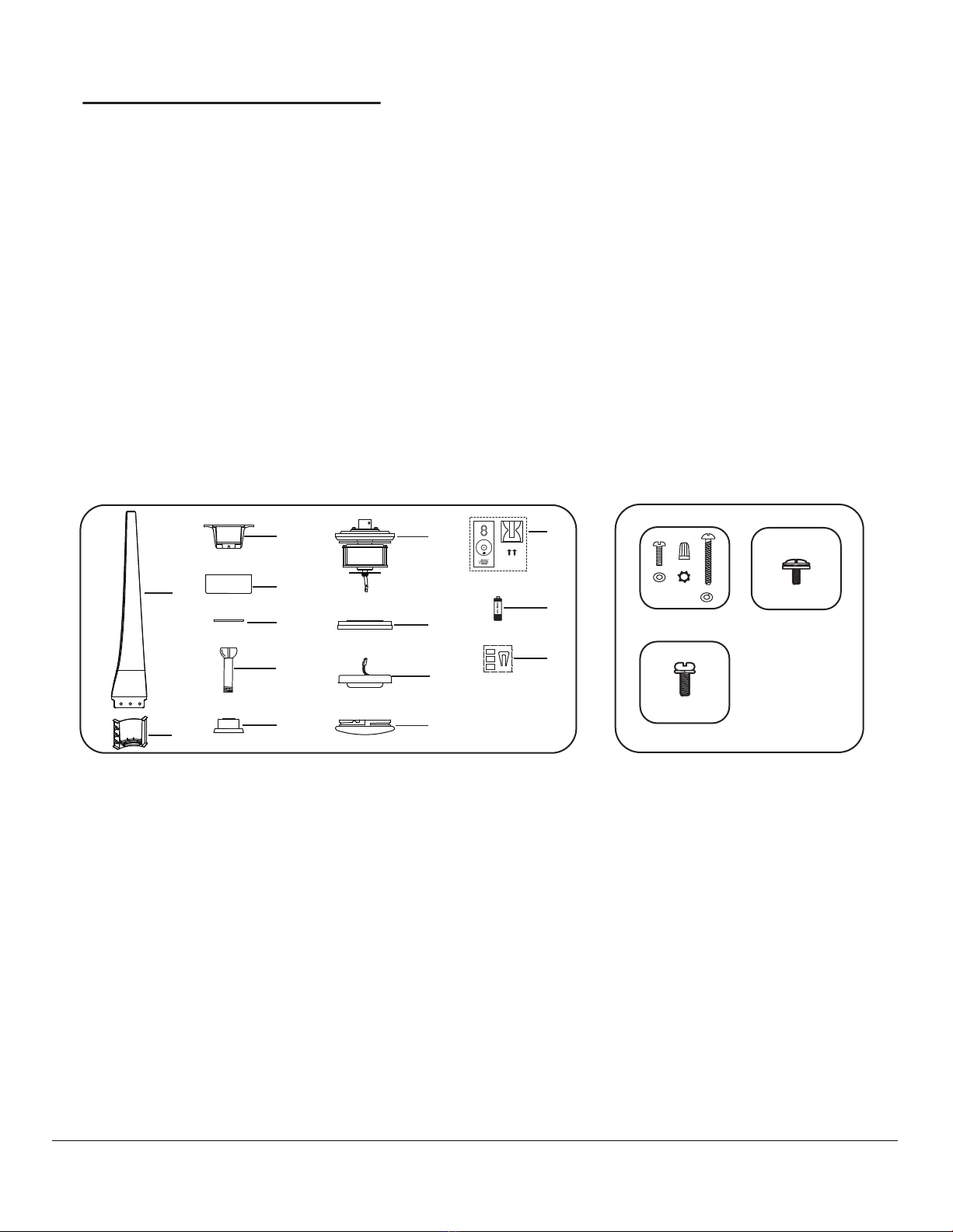
CONTENTS
SAFETY RULES............................................................................
PACKAGE CONTENTS..................................................................
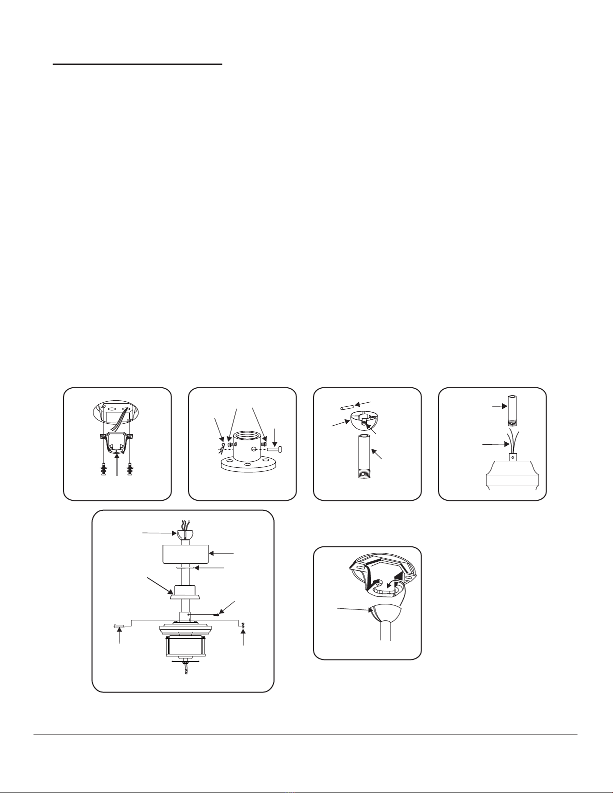
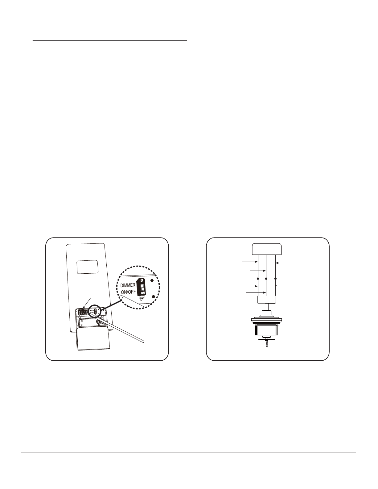
INSTALLING THE FAN..................................................................
HANGING THE FAN......................................................................
ELECTRICAL CONNECTIONS........................................................
FINISHING THE INSTALLATION....................................................
ATTACHING THE FAN BLADES....................................................
INSTALLING THE MOUNTING PLATE.......................................
INSTALLING THE LIGHT KIT....................................................
INSTALLING THE GLASS SHADE............................................
OPERATING THE REMOTE CONTROL......................................
CARE OF YOUR FAN...............................................................
TROUBLESHOOTING..............................................................
SPECIFICATIONS...................................................................
4
5
6
7
8
9
10
10
11
12
13
15
16
17