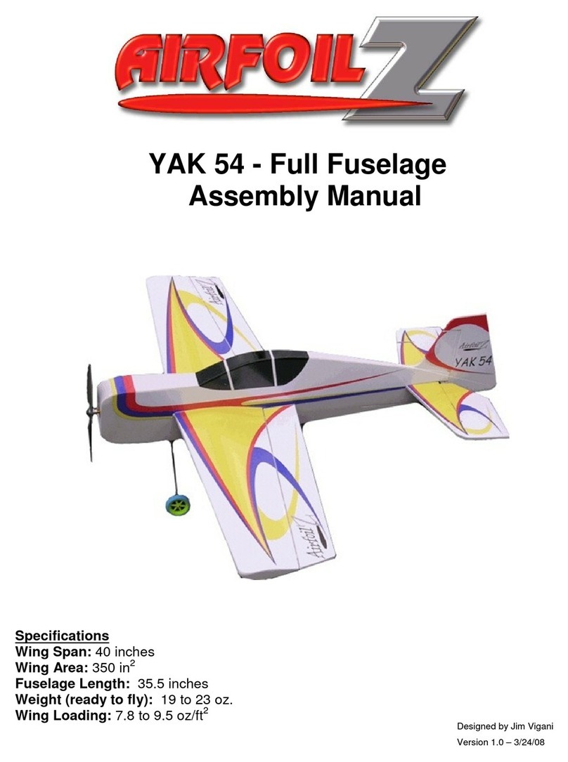
AirfoilZ YAK54 User manual

LIMITED WARRANTY
AirfoilZ takes pride in the care and attention given to manufacturing of the components in this kit. The Company
warrants replacement of any materials found to be defective for their intended use prior to their usage in the
construction of the model, provided that the purchaser requests such replacement within a one year period
from the date of purchase and that the purchaser returns the part if the Company so requests. No other warranty,
expressed or implied, is made by the Company with respect to this kit. The purchaser assumes full responsibility
for the risk and all liability for personal or property damage or injury resulting from the purchaser’s use of the
components of this kit, assembled or not.
The Company reserves the right to provide a full refund to the purchaser if the model does not perform as adver-
tised. Any refund is at the sole discretion of the Company.
A TECH HOBBIES, LLC COMPANY
P. O. Box 301
Edison, New Jersey 08817
Tel: 732.406.5726
Fax: 732.467.5504
Web: www.airfoilz.com
Email: [email protected]
© 2007 ALL RIGHTS RESERVED
WINGSPAN
WING AREA
FUSELAGE LENGTH
WEIGHT (READY TO FLY)
WING LOADING
40 inches
350 sq in
35.5 inches
16 to 20 oz
5.8 to 7.0 oz/sq ft

TABLE OF CONTENTS
INTRODUCTION
POWER SYSTEM RECOMMENDATION
ADDITIONAL ITEMS REQUIRED
3.1 Building Supplies
3.2 Power & Control Equipment
KIT CONTENTS
ASSEMBLY TIPS
FUSELAGE ASSEMBLY
6.1 Motor Mount
6.2 Landing Gear Mount
WING ASSEMBLY & INSTALLATION
7.1 Assembling the Spar
7.2 Wing Panel Assembly
7.3 Wing/Fuselage Assembly
TAIL FEATHER ASSEMBLY &
INSTALLATION
8.1 Joiner
8.2 Installing the Horizontal & Vertical
Stabilizer
8.3 Installing the Elevator
8.4 Installing the Rudder
8.5 Aileron Installation
SERVO, PUSHROD, & CONTROL
HORN INSTALLATION
9.1 Elevator & Rudder Servo Installation
9.2 Control Horn Installation
9.3 Push Rod Assembly & Installation
LANDING GEAR INSTALLATION
10.1 Main Landing Gear
10.2 Tail Skid
WWW.AIRFOILZ.COM
2
USING THIS MANUAL
Read through this manual before beginning construction
on your model. The manual contains important tips, warn-
ings, and instructions concerning the assembly and use of
this model. Refer to the Table of Contents below to locate
answers to specic questions.
1.
2.
3.
4.
5.
6.
7.
8.
9.
10.
3
3
3
3
4
4
6
6
6
8
9
9
11
14
15
16
17
19
19
20
21
21
22
23
24
24
24
MOTOR, ESC, RECEIVER, & BATTERY
INSTALLATION
11.1 Motor Setup
11.2 Motor Mounting
11.3 Electronics Mounting
APPLYING THE VINYL GRAPHICS
CONTROLS
PREFLIGHT CHECK
14.1 Balancing
14.2 Range Check
14.3 Inspection
11.
12.
13.
14.
25
25
25
26
26
27
27
27
27
27

© 2007 ALL RIGHTS RESERVED 3
INTRODUCTION
1POWER SYSTEM
2
Thank you for choosing the AirfoilZ Yak54 airplane. We
have taken great care to provide a design and kit com-
ponents that, when properly assembled, will give you
a high quality model with outstanding performance.
While the assembly is not complicated, the quality and
ultimate performance of your model will depend a great
deal on the care you take while building. Please read
these instructions carefully and be sure that you under-
stand them before you start. Take care to assemble the
components as shown and in proper alignment.
This plane has been designed using a Hacker A20-20L
Brushless Motor with a Hacker X-20 Speed Controller and
Thunder Power 1320 mah, 3S Li-poly battery, turning an
APC, 10 x 4.7 Slow Flyer propeller. Other power systems
with similar capabilities can be used. Performance will
vary depending on the specic power system selected.
For information on alternate power systems please visit
http://www.airfoilz.com/forums.
ADDITIONAL ITEMS
3
In addition to the kit contents, we recommend having
the following building supplies on hand to complete the
kit assembly in accordance with this manual.
Foam safe (odorless) CA
Foam safe CA“Kicker”
Thin CA
Gorilla glue and/or 5 and 15 min epoxy
JB Weld
Double back tape or spray adhesive
Low tack masking tape (blue painter’s tape)
Sanding block with 100 grit sandpaper
Sanding stick or emery board (150 grit)
Craft Popsicle-size wooden sticks
Soldering iron and resin core solder
1/32 inch and 3/32 inch diameter drill bits
Exacto knife with #11 blade
Utility knife
Small square
36 inch ruler
Needle nose pliers
3/8 inch diameter brass tubing
½ inch diameter brass tubing
Dremel tool with abrasive cuto wheel
Diagonal cutting pliers
REQUIRED
Building Supplies
3.1
RECOMMENDATION
This radio-controlled model is not a toy and, if operat-
ed inappropriately, can cause serious bodily injury and
property damage. It is the buyer’s responsibility to as-
semble the kit correctly and to properly install the mo-
tor, radio, and all other equipment. The model must al-
ways be own in accordance with the safety standards
of the Academy of Model Aeronautics (AMA).
This model is designed to be fully 3D capable. While
it is reasonably simple to assemble, it is not intended
for the novice ier. Do not attempt to learn to y with
this model! If you are an inexperienced modeler, we
recommend that you get the assistance of an experi-
enced modeler to help you with the assembly and ini-
tial ights. There are many local clubs that can oer
help with assembly and ight instruction. Information
on local clubs may be found through the Academy of
Model Aeronautics (AMA) at www.modelaircraft.org.
The AMA has over 2500 chartered clubs throughout
the country.
We do not recommend the use of hot glue for mount-
ing components such as servos, control horns, receiv-
ers, or speed controls.
WARNING

WWW.AIRFOILZ.COM
4
The following items are needed to provide power and
control function to your model.
Brushless outrunner motor with radial mount (Hack-
er A20-20L or equivalent)
8 motor mounting screws
4 washers (#2)
Brushless motor speed control (Hacker X20 or equiv-
alent)
4 micro servos (Hitec HS-55 or equivalent for hard 3-
D use HS-56)
3S Li-poly battery pack (TP 1320 Pro-Lite or equiva-
lent)
LI-poly battery charger
4 or 5 channel (with channel 6 capability) micro re-
ceiver
Y harness if 4 channel receiver is selected
4 or 6 channel transmitter
Power & Control Equipment
3.2
KIT CONTENTS
4
Before you begin assembly of this model, make sure that
there are no missing parts and that these parts have not
been damaged during shipment. If you have questions
regarding assembly or ying of this model, please con-
tact us, and we will be happy to assist you. If you need re-
placement parts, please provide the model name (Yak54)
and reference the part numbers listed to the right.
PART # QTY DESCRIPTION
YF-01 1 Laminated foam fuselage
YF-02 2 1/32” plastic nose doubler
YF-03 1 1/8” plywood motor mount
YF-03a 1 3/8” balsa tri stock motor mount
support
YF-05 1 Hardwood landing gear mount
YF-05a 1 1/32” ply landing gear mount cap
YF-05b 2 1/32” plastic landing gear mount
fuselage doubler
YF-06 1 3/32” diameter bent wire landing
gear
YF-06a 1 1/32” diameter bent wire tailskid
YF-06b 1 1/32” ply tailskid mount
YF-07 2 3mm formed depron wing panel
YF-07a 2 3mm depron wing panel
alignment tabs
YF-07b1 1 1 balsa wing spar web main
YF-07b2 1 Balsa wing spar web tip
YF-07b3 2 Balsa wing spar cap main
YF-07b4 2 Balsa wing spar cap tip
YF-07c 2 6mm depron ailerons
YF-07d 2 3mm depron wing tip caps
YF-08 1 6mm depron horizontal stabilizer
YF-08a 1 6mm depron elevator
YF-08c 1 3/16” dia. x 5” long CF elevator joiner
YF-09 2 3mm depron vertical stabilizer ller
piece
YF-09a 1 6mm depron vertical stabilizer
YF-09b 1 6mm depron rudder
YF-09c 1 ¼” sq. balsa tail post
FUSELAGE ASSEMBLY PARTS
YF-01
YF-03 YF-03A x 2
YF-02 x 2

TAIL ASSEMBLY PARTS
WING PANEL PARTS
SPAR ASSEMBLY PARTS
© 2007 ALL RIGHTS RESERVED 5
WING ASSEMBLY PARTS
YF-05b x 2
YF-05
YF-05a
YF-07b1 YF-07b2
YF-07b3 x 2 YF-07b4 x 2
YF-07 x 2
YF-07a x 2 YF-07d x 2
YF-09c
YF-09 x 2
YF-08c
YF-08a
YF-08
Hinges

HARDWARE PACKAGE
FSM-01 8 ¼” x 1” x 1/32” plastic servo mount
MH-001 16 Hinges
MH-002 2 Dubro duro collars w/screws
MH-003 2 #2 washers
MH-004 4 Double threaded 2-56 control rod
MH-006 1 1/8”dia. x 24”CF push rod blank
MH-007 8 Nylon clevises
MH-008 4 Plastic control horns
MH-009 1 2”(4”?) long heat shrink tubing
MH-011 2 Spoked lightweight foam wheels
YF-DS 1 Decal set
YF-IM 1 Instruction manual???
WWW.AIRFOILZ.COM
6
ASSEMBLY TIPS
5
To ensure maximum performance from your model,
it is necessary to build it straight and light. Improperly
aligned surfaces and unnecessary weight will only hin-
der its performance. Apply glue and epoxy in a thin, uni-
form coat, using only enough to achieve a strong bond.
Excess glue or epoxy will only add weight and will not
FUSELAGE ASSEMBLY
6
Motor Mount
6.1
Locate the fuselage (YF-01), plastic nose doublers (YF-
02), plywood motor mount (YF-03), and tri-stock motor
mount supports (YF-03a) (Figure 1).
increase the strength of your model. Trial t all compo-
nents before applying any glue or epoxy. Keeping joints
tight-tting will minimize the amount of glue required
and will help ensure a strong bond.
Use a light touch while sanding. Foam cuts very quickly,
and excess pressure can limit your ability to accurately
shape the foam. Take extra care not to over-sand. Avoid
scratching the surface of the Depron foam.While sanding
components such as the wing tip caps, you may choose
to use blue painter’s tape to protect the adjacent wing
surfaces from accidental contact by the sanding block.
FIGURE 1
YF-01
YF-03 YF-03A x 2
YF-02 x 2
Carefully glue the nose doublers in place with foam safe
CA or 12 minute epoxy, being careful to align the dou-
blers with the motor cutout in the fuselage and with
each other. (See Figure 2.)

FIGURE 4
FIGURE 3
© 2007 ALL RIGHTS RESERVED 7
FIGURE 2
After the glue has set on the nose doublers, slide the mo-
tor mount/rewall in place from the front. If the notches
in the motor mount are too small, lightly sand or le until
the motor mount ts properly. Check the t before apply-
ing any epoxy. Also, check that the interior corners of the
motor mount cutout are square. Once the motor mount
ts and is square to the fuselage in both directions as
shown in Figures 3 and 4, remove motor mount and glue
to the fuselage using epoxy. Check again to ensure that
the motor mount is square to the fuselage.
The balsa tri-stock will need to be trimmed to the
proper length. Mark the balsa tri-stock motor mount
supports to match the shape and length of the motor
mount (Figure 5). Cut the tri-stock and sand to shape.
Check the t against the motor mount. When satised
with the t, apply epoxy to tri-stock where it contacts
the motor mount and nose doublers (Figures 6 and 7).
Check again to ensure that the motor mount is square
to the fuselage both vertically and horizontally. Allow
the epoxy to set before moving on.
FIGURE 5

WWW.AIRFOILZ.COM
8
FIGURE 6
FIGURE 7
Landing Gear Mount
6.2
Locate the hardwood landing gear mount (YF-05), the
plywood landing gear mount cap (YF-05a), and the 2
plastic landing gear mount fuselage doublers (YF-05b)
(Figure 8).
FIGURE 8
YF-05b x 2
YF-05
YF-05a
Epoxy the cap to the mount to create the landing gear
block. See Figure 9.
FIGURE 9

© 2007 ALL RIGHTS RESERVED 9
Test t the block in the cutout in the fuselage. If neces-
sary, carefully sand the fuselage to widen it. Square up
the cutout end in the fuselage if necessary so that the
block will t completely into the fuselage. VERY IM-
PORTANT: Sand the sides of the block as necessary so
that the edges of the block are even with the surface of
the fuselage sides. File several grooves into the sides of
the block as shown in Figure 10.
FIGURE 10
For added strength, wrap the assembled block with
several loops of unwaxed dental oss (Figure 11). The
grooves should be just deep enough so that the dental
oss does not protrude above the surface of the fuse-
lage when the block is in place. Glue the dental oss in
place with thin CA.
FIGURE 11
WING ASSEMBLY
7
Assembling the Spar
7.1
Locate the balsa wing spar components: web parts (YF-
07b1and YF-07b2) and cap strip parts (YF-07b3 and YF-
07b4). The spar web is the thick balsa, and the cap strips
are the two sets of thinner balsa. See Figure 13 on the
following page.
& INSTALLATION
Check the t of the landing gear wire in the slot. When
satised with the t, epoxy the block to the fuselage,
being careful not to get epoxy in the hole in the middle
of the block. Next, epoxy the plastic landing gear mount
fuselage doublers in place over the block as shown in
Figure 12.
FIGURE 12

WWW.AIRFOILZ.COM
10
FIGURE 13
YF-07b1 YF-07b2
YF-07b3 x 2 YF-07b4 x 2
Align the spar web parts and hold them against a ruler
to make a straight piece. Glue together with thin CA. Use
a piece of waxed paper under the glue joint to prevent
sticking to the work surface. Repeat the assembly pro-
cedure with the cap strip parts. (Note: if the cut angles
don’t match perfectly, just sand or re-cut one angle
to match the other one; it’s not a critical part of the
spar assembly. The overall length of the nished spar
is 39-7/8”, give or take 1/4”.) See Figure 14.
FIGURE 14
Lay one of the cap strips (thin balsa) at on your work
surface and position the spar web (thick balsa) along the
center of the cap strip. Starting at one end, tack the web
in place at 6-inch increments with thin CA, rmly push-
ing the web in place as you glue. See Figures 15 and 16.
FIGURE 15
FIGURE 16

© 2007 ALL RIGHTS RESERVED 11
Repeat the process with the other cap strip, being sure
to place the cap strip splice joint at the opposite end
of the spar from the rst cap strip splice joint. See
Figures 17 and 18.
FIGURE 17
FIGURE 18
When both cap strips are tacked in place, run a bead of
thin CA along the joints between the web and caps strips.
Trim o any excess length of the completed assembly.
The nished length should about ¼” inch shorter than
the two wing halves when pressed together. You will
trim the length to t in the next section. The completed
spar resembles an “I” beam.
Wing Panel Assembly
7.2
Locate the two wing panels (YF-07), the two wing panel
alignment tabs (YF-07a), and the two wing tip caps (YF-
07d). See Figure 19.
FIGURE 19
YF-07 x 2
YF-07a x 2 YF-07d x 2
Place a mark 2 1/8”behind the leading edge at each wing
tip (Figure 20). Place another mark 3 1/8”behind the lead-
ing edge at each wing root (Figure 21). These marks will
be used for aligning the wing spar.
FIGURE 20

WWW.AIRFOILZ.COM
12
FIGURE 21
Take the spar assembly and sand a slight bevel on the
edge of the cap strip all the way from one end to the oth-
er. Flip the spar over and repeat.The bevels should be on
opposite sides of the spar. See Figure 22. Some people
prefer to round the end of the spar just slightly to aid in
inserting into the wing and to help avoid damage to the
inside of the wing as the spar is slid in.
FIGURE 22
Measure to nd the center of the spar and make a mark
on it. Apply a bead of Gorilla Glue to the top and bottom
of the spar from the center point out toward the left tip.
Lightly mist the glue with water. Turn the spar on its side
and insert it into the left wing panel, being careful not
to smear the glue onto the wing. Line up the spar with
the center marks made previously on both the root and
edge of the wing as shown in Figure 23.
FIGURE 23
Twist the spar toward the bevel you made so that the
spar is upright and resembles an “I” beam. The bevel you
sanded in the previous step will help the spar to twist
into position more easily. Sometimes it helps to have a
helper twist one end of the spar while you twist the oth-
er and hold the wing. Position the centerline of the spar
along the marks you made earlier and ensure that the
spar caps are in contact with the inside of the wing skin
surface. See Figure 24. Make sure that the spar does not
extend past the end of the wingtip; it should be about
1/8” in from the tip of the wing. See Figure 25. The spar
is a snug t in the wing panel. The wing panel will take
the proper airfoil shape after the spar is in place. The Go-
rilla Glue will expand as it dries; be sure and wipe any
excess o of the wingtip and wing root.
FIGURE 24

© 2007 ALL RIGHTS RESERVED 13
FIGURE 25
Place the other wing panel on top of the spar and verify
the length once again. The spar should be just inside the
wingtip on the end of the wing. If necessary, use a saw
and trim the length so that the spar does not extend past
the end of the wing. When satised, set the wing half to
the side and cut each alignment tab into two pieces as
shown in Figure 26.
FIGURE 26
Glue the alignment tabs in place on the left wing panel
(the one with the spar already in it) as shown in Figure
27. Use foam safe CA and leave some room on either side
of the spar.
FIGURE 27
Apply a bead of Gorilla Glue to both sides of the spar, just
as you did for the rst wing half (Figure 28).
FIGURE 28
Slide the other wing half over the spar as shown in Figure
29. Don’t slide it all the way on; stop short of the align-
ment tabs.

WWW.AIRFOILZ.COM
14
FIGURE 29
Just like we twisted the other wing half, we now want
to twist this one into position. Twist in the direction of
the bevel on the spar (you may have to slide the wing
back o, ip it, and slide it back on). Once again, it may
be easier to have someone reach in with pliers or ngers
to hold/twist the other end of the spar.
FIGURE 30
Before sliding the wing all the way in, apply foam safe CA
to the other half of the alignment tabs on the top and
bottom of the wing. Slide the wing over the alignment
tabs and ush against the other wing half. The wing as-
sembly should now look like Figure 31.
FIGURE 31
Carefully sand the wing tip with a sanding block to re-
move any irregularities. Glue the wing tip caps onto the
wing using foam safe CA and foam safe kicker (Figure
32).
FIGURE 32
Using an X-Acto knife, trim the wing tip cap to the shape
of the wing. The front edge of the wing tip cap will need
to curve around the leading edge of the wing. You may
need to trim it with a knife to get it to t the front of the
wing. Carefully sand the wing tip cap ush with the wing
itself, being careful not to scratch the wing surface (Fig-
ure 33).
FIGURE 33
Wing/Fuselage Assembly
7.3
Test t the wing into the fuselage wing cutout. Do not
force! If the t is tight, carefully sand the opening with
the sanding stick or emery board until the wing slides
smoothly into the cutout. The wing can be joined to the
fuselage with either epoxy or Gorilla Glue. If simply glu-
ing the wing in place, we recommend using Gorilla Glue.
Slide the wing out approximately ¾ inch and apply the
glue to the wing centerline. Lightly mist with water and

TAIL FEATHER ASSEMBLY
8& INSTALLATION
© 2007 ALL RIGHTS RESERVED 15
slide the wing back in place. Carefully align the wing
with the fuselage and check that the distance from the
trailing edge at each wing, tip to the rear of the fuselage,
is the same. See Figure 34.
FIGURE 34
Also, check that the fuselage is square to the wing sur-
face (Figure 35). Temporarily secure with painter’s tape.
FIGURE 35
An alternate method is to align the wing as in Figure 35
and tack it in place using foam safe CA. The wing can
then be permanently glued in position by creating a llet
using a mixture of 15 minute epoxy and micro balloons.
This method provides both a strong and attractive wing
joint as shown in Figure 36.
FIGURE 36
Locate the 6mm depron horizontal stabilizer (YF-08), the
6mm depron elevator (YF-08a), the 3/16” diameter x 5”
long elevator joiner (YF-08c), the 6mm depron vertical
stabilizer (YF-09a), the two 3mm depron vertical stabiliz-
er ller pieces, the 6mm depron rudder (YF-09b), the ¼”
sq. balsa tail post, and seven Klett pin hinges (MH-001).
See Figure 37 on the following page.

WWW.AIRFOILZ.COM
16
FIGURE 37
YF-09c
YF-09 x 2
YF-08c
YF-08a
YF-08
Hinges
Joiner
8.1
Using the end of the elevator joiner, gently create a shal-
low groove in the elevator joiner cutout (Figure 38).
FIGURE 38
Secure the joiner in place with epoxy. For a lighter joint,
a mixture of 15 minute epoxy and micro balloons can be
used. See Figure 39.
FIGURE 39

© 2007 ALL RIGHTS RESERVED 17
Securing the horizontal
8.2
When the epoxy has cured, check the t between the
horizontal stabilizer and the elevator. There should be
approximately 1/32” clearance between the outside
edges of the stabilizer and the elevator. Trim with your
X-Acto knife if necessary. Using the sanding block, bevel
the leading edge of the elevator as shown. (See Figure
40, which shows the rudder instead of the elevator, but
it is easier to see the bevel on the rudder.) The bevel will
allow for movement of the elevator when hinged. If you
want extreme travel throw on the elevator, you can also
bevel the trailing edge of the horizontal stabilizer slight-
ly.
& VERTICAL STABILIZER
FIGURE 40
Cut out the foam connecting section at the center eleva-
tor using your X-Acto knife (Figure 41).
FIGURE 41
Cut out the ashing at the rear of the fuselage above the
stabilizer slot, taking care not to crack the outside skin
(Figure 42).
FIGURE 42
If you choose, the leading edge of the horizontal and
vertical stabilizer, along with the trailing edge and tips of
the elevator and rudder, can be sanded round using the
sanding block. Check the t of the horizontal stabilizer
in the slot at the rear of the fuselage. If necessary, gently
sand the slot with the sanding stick until the stabilizer
can be positioned parallel to the wing (Figure 43).
FIGURE 43
Check the t of the vertical stabilizer tabs in the slots in
the horizontal stabilizer. Trim as necessary for a snug t
(Figure 44).

WWW.AIRFOILZ.COM
18
FIGURE 44
Join the vertical and horizontal stabilizer and tack into
position using foam safe CA. Make sure the surfaces are
square. Glue the 3mm depron vertical stabilizer ller
pieces in place on either side of the rudder (Figure 45).
If you plan on ying a lot of hard 3-D type ying it might
be a good idea to make a slit in the bottom of the hori-
zontal stabilizer and insert a at piece of carbon ber to
act as a spar. It will strengthen and stien the horizontal
stabilizer and elevator. You can generally nd carbon
ber pieces like this at your local hobby shop. A piece
about 12 inches long by 1/8” wide by 1/64” thick would
work well. This modication is shown in Figure 46 if you
should choose to do it.
FIGURE 45
Check the t of the stabilizer assembly in the slot at the
rear of the fuselage. If required, use your sanding stick to
sand the slot in the fuse to allow the stabilizer to be par-
allel to the wings. Carefully glue the stabilizer assembly
in place using epoxy. Temporarily secure the assembly
in proper alignment using two craft sticks and painter’s
tape. Make sure the horizontal stabilizer is parallel with
the wing before the epoxy cures (Figure 47). Also, check
to make sure that the tip of each side of the trailing edge
of the horizontal stabilizer is the same distance from the
wing tip before the epoxy cures (Figure 48). This will help
ensure that the horizontal stabilizer is squared up to the
fuselage.
FIGURE 47
FIGURE 46

© 2007 ALL RIGHTS RESERVED 19
FIGURE 48
When the epoxy has cured, check that the back of the
vertical stabilizer and the back of the fuselage are ush.
Sand as necessary with the sanding block.
Installing the Elevator
8.3
Slide the elevator into position and temporarily secure
with tape. Mark the position of the elevator hinges with
strips of 3/8” wide painter’s tape (Figure 49).
FIGURE 49
Cut the tape along the hinge line and remove the eleva-
tor (Figure 50).
FIGURE 50
Using your X-Acto knife, carefully cut a slit along the cen-
terline of both the stabilizer and elevator at each hinge
location. Test t the hinges into the slits. Check that the
elevator can move at least 50 degrees in each direction.
If necessary, widen the slot in the fuselage at the CF ele-
vator joiner location to allow full travel. When all parts t
properly, apply a small amount of epoxy inside the slits
on the elevator and wipe o any excess. Insert the hinges
into the elevator. You want the hinge ex point to be just
past the elevator and all four hinges to be inserted the
same amount. Allow the epoxy to set a bit and mix up
some fresh epoxy. Once again, place some epoxy into the
slits on the horizontal stabilizer. Insert the hinges from
the elevator into the horizontal stabilizer, sliding the el-
evator so that all hinges are seated equally. You want the
hinge line to be as tight as possible while still allowing
full range of movement. Flex the elevator in both direc-
tions to make sure that it travels the full amount before
the epoxy sets. If necessary, pull the elevator out just a
bit to allow for more travel.
Installing the Rudder
8.4
Measure the length of the vertical stabilizer from the top
to the bottom of the fuselage, and then cut the rudder
post to match that length. It is easiest to cut the post a
little long and then sand smooth and ush with the top
of the vertical stabilizer and the bottom of the fuselage.
Glue the rudder post into position with medium foam
safe CA as shown in Figure 51.

WWW.AIRFOILZ.COM
20
Temporarily secure the rudder in position using painter’s
tape. Remember to leave approximately 1/32” clearance
between the top of the vertical stabilizer and the rudder.
Mark the position of the rudder hinges with strips of 3/8”
wide painter’s tape. Cut the tape along the hinge line
and remove the rudder. Using your X-Acto knife, careful-
ly cut a slit along the centerline of both the rudder post
and the rudder at each hinge location. Install the hinges
using the same procedure as used for the elevator. See
Figure 53.
FIGURE 53
Aileron Installation
8.5
Locate the 6mm depron ailerons (YF-07d) and eight
hinges (MH-001). Bevel the leading edge of the aileron
as shown in Figure 54 to allow for movement of the aile-
ron when hinged.
FIGURE 54
If you choose, the trailing edge and tips of the ailerons
can be sanded round using the sanding block. Tempo-
rarily secure the ailerons in position using painter’s tape.
Mark the position of the aileron hinges with strips of 3/8”
wide painter’s tape (Figure 55).
Trim the sides of the fuselage under the horizontal stabi-
lizer with an X-Acto knife to make enough room for the
rudder control horn to clear the side of the fuselage (Fig-
ure 52).
FIGURE 52
FIGURE 51
Other manuals for YAK54
1
Table of contents
Other AirfoilZ Toy manuals
Popular Toy manuals by other brands

THE DICETROYERS
THE DICETROYERS THE SYNAGOGUE GOLEM COMPATIBLE MARBLE... quick guide

Dynam
Dynam F4U Corsair instruction manual

juguettos
juguettos Pasarela user guide

Eduard
Eduard Do 215B interior S.A. quick start guide

wiking
wiking Control87 077426 operating instructions

HQ Kites & Design
HQ Kites & Design Constellation owner's manual