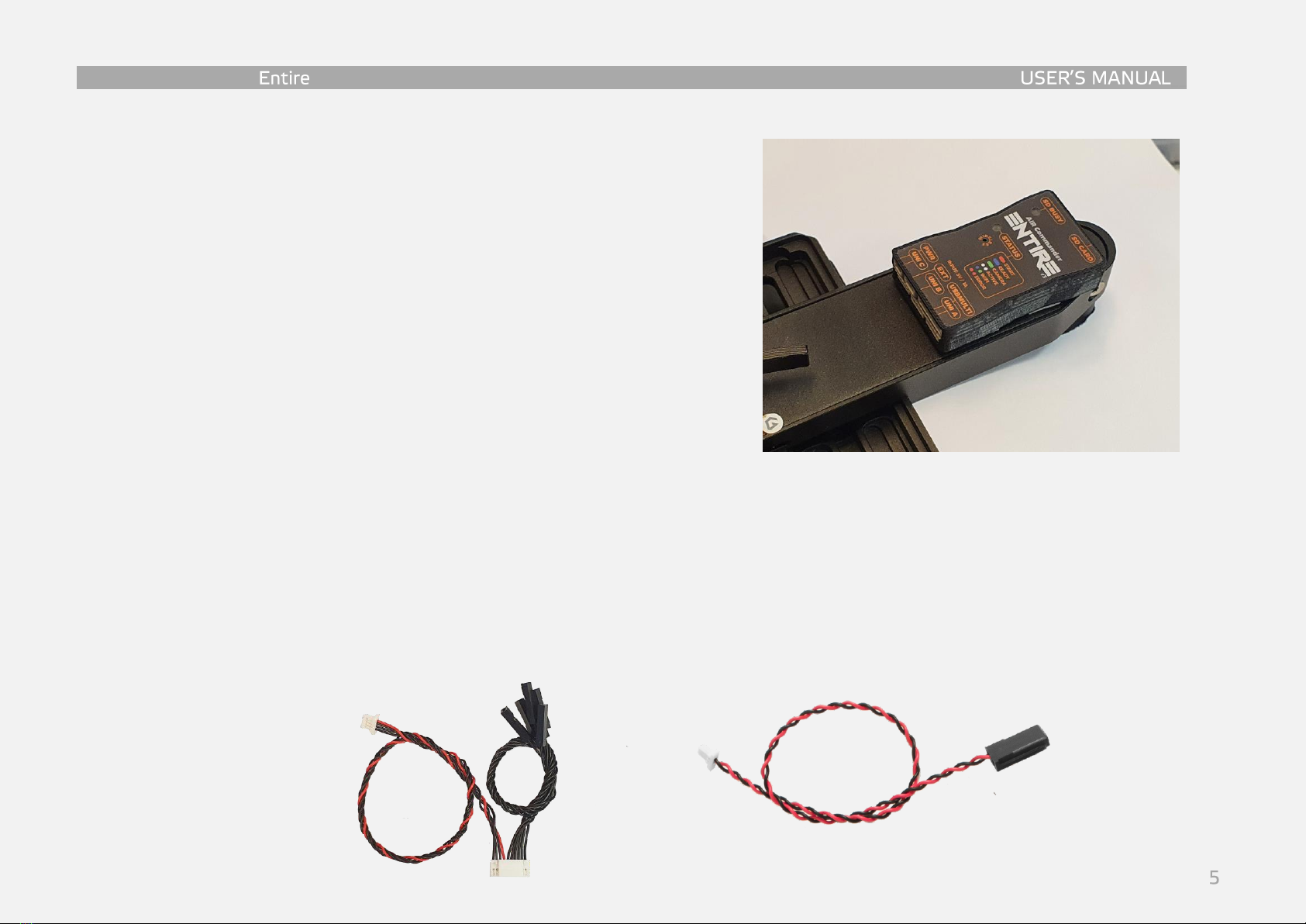
Airpixel Wired Geotagging r3 User manual

airpixel.cz
Wired Geotagging r3 (Gremsy)

AIR Commander
GeoTagging overview
GeoTagging mode is enabled via MENU -> Logging mode, where you can select “SD Card” option for
saving GPS/RTK data to the SD card in the Entire’s microSD slot, or “Direct (EXIF)” for direct upload of
coordinates into the EXIF of photos in the camera. In “Direct (EXIF)” mode.
No USB camera control is available (only Infra-Red commanding) in geotagging modes.
Direct (EXIF) mode & SD Card mode
-Camera must be set up into “Mass storage” USB mode, WiFi control is available in this mode
for newer Sony cameras (A7R3, A7R4, A6600, RX100V, RX100VI). WiFi control will be lost during
USB connection (after takeoff and after landing). Entire will re-establish WiFi connection back
once USB will be disconnected.
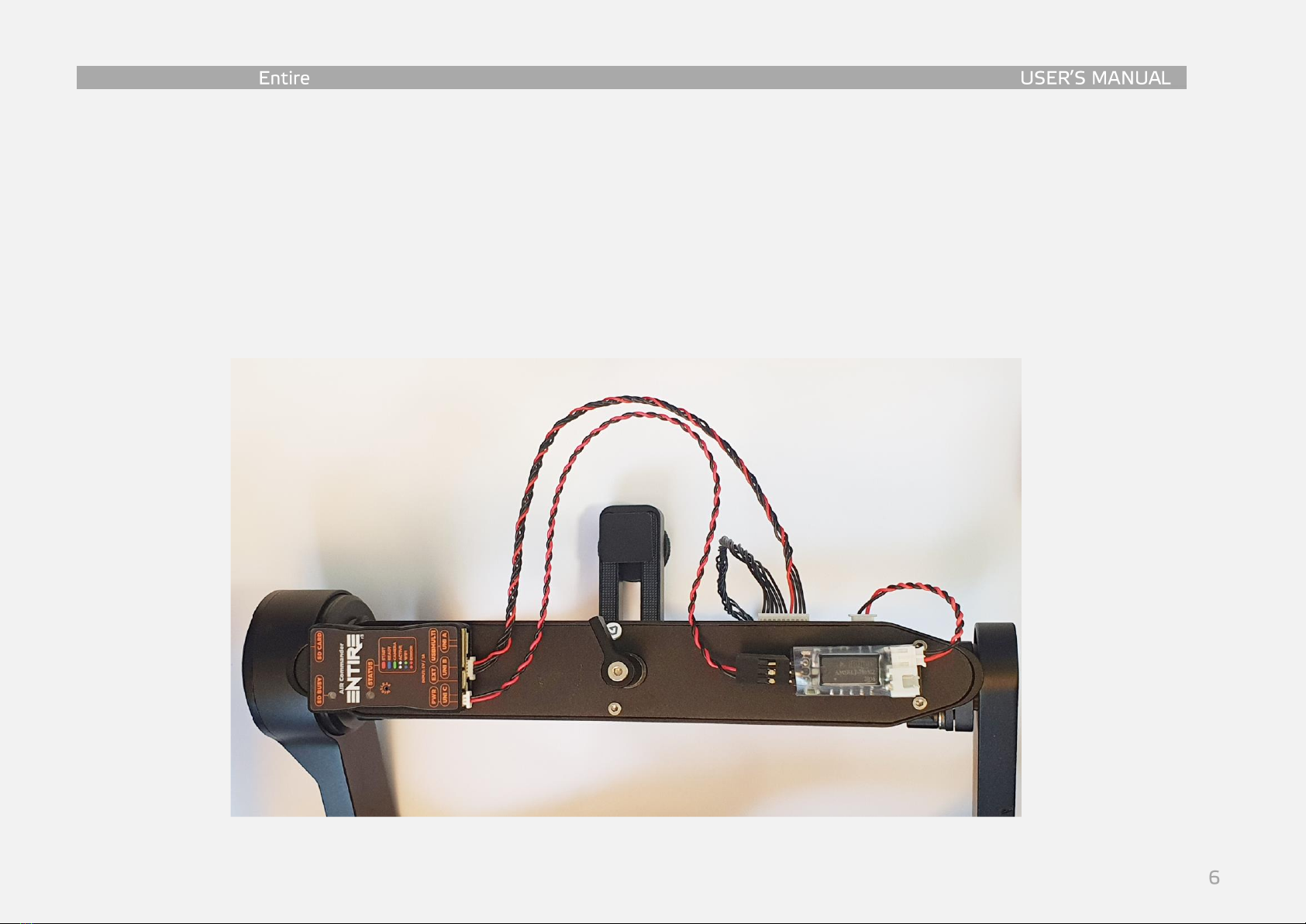
-Photo triggering available via MavLink bus for the Pixhawk drones, or via PWM for DJI drones.
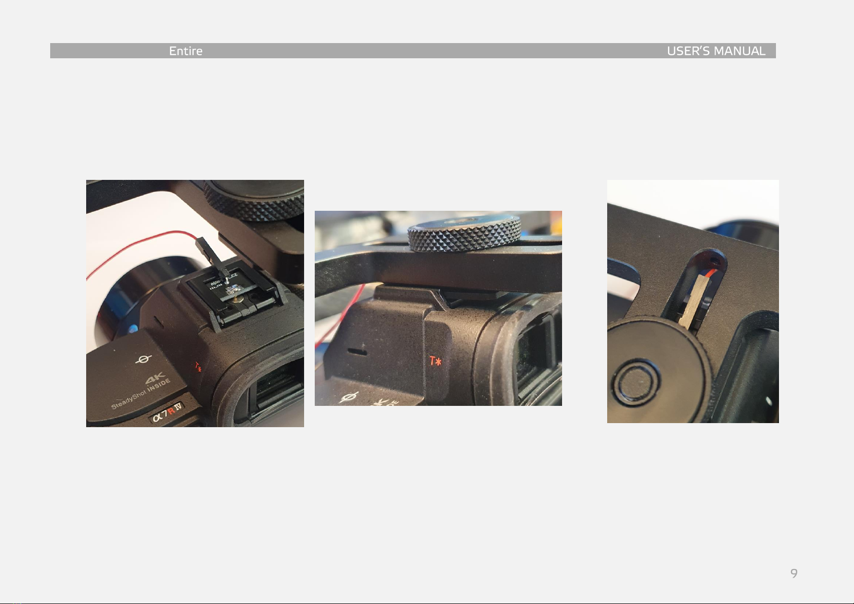
-IR commands are also available for cameras with IR port (whole Sony A7 series)
oISO, Exposure correction, MENU (and navigation), Photo review, Zoom, Video start/stop
-No matter if “Direct(EXIF)”or “SD Card”mode is selected, text backup version is copied to SD
card of the Entire (if inserted). If “Direct(EXIF)” mode is selected, backup TXT file is also copied to
SD card of the Camera. Third copy of geotag data is available for download in the Entire’s web
configuration (CONTROL -> “Download GeoTag backup file”).

AIR Commander
Capture detection
Accuracy of the exact capture time is highly important. AIR Commander Entire triggers the capture
via multiport USB or IR commands (user selectable). Even the trigger is highly reliable, in the real
world there is still option of failure of camera AF or other system, which causes missing photo in the
log row. Missing photo will cause overrun and wrong information on all next photos. We have two
options for the user.
-“HotShoe sync” mode - suggested option. Additional bracket is used to sense the photo trigger
from the Flash connector on the camera body. Extremely accurate in time precision and also
avoids missed captures.
-“Predefined delay” mode - less accurate option, which actually does not sense if the real
capture has happen. However especially for the multiport triggering the time accuracy is
pretty good.
GPS / RTK selection
AIR Commander Entire selects automatically the RTK coordinates if they are available at the DJI API input.
If they are not available, GPS is used automatically.

AIR Commander
Wiring overview:

AIR Commander
Wired GeoTagging connection –DJI/PixHawk
For the GeoTagging mode the AIR Commander Entire must be connected to the Camera via Sony
Multiport Cable (this is frequently mismatched, please check photos at the end of the manual), and also must be
connected to the DJI Flight Controller API connector. Cable set for API connection is available at the
Shop. There are few options about triggering of the camera during mission.
a) Using DJI Remote (RSS) (suggested) –in this option you MUST use the HotShoe sensor and you can skip lines marked
b) Using the Entire’s internal functions of timed triggering or distance trigger functions (also suggested). You can skip
lines marked
c) Using F port triggering. In this mode you have to follow all lines of bottom process.
-Step 1 –Power Adaptor mount (Gremsy T3v3)
oLet’s start with mount of Power Adaptor to the Gremsy gimbal.
oConnect included Gremsy power cable to the PWT OUT of the gimbal
oConnect power cable to the lower connector (at the photo)
oUse double self-adhesive tape, Zip Ties or self-adhesive zipper.

AIR Commander
-Step 2 –Entire mount (Gremsy T3v3)
oMount the Entire unit at the other side of the bottom of gimbal.
oSD Card should be aimed outside of the gimbal for easy handling
in the fields.
oUse double self-adhesive tape or self-adhesive zipper is
suggested.
-Step 3a –Wiring
oConnect Power Adaptor to the Entire (PWR connector) via Power
cable
oConnect Gremsy AUX port to the UNI B port of the Entire by AUX
Cable

AIR Commander
-Step 3b –Wiring
oAUX Cable has two separate twisted groups of cables. One has red wire included and is connected to
UNI-B of the Entire. Second group of cables with single wire connectors at the end are unused AUX pins.
oUnused pins of AUX port (black wires) can be used for any additional connection same way as original
AUX cable included to the gimbal. In our case we remove these pins from AUX connector because all
data and control signals are transferred via UNI-B connection.

AIR Commander
-Step 4 –Wiring
oClean up wires under the gimbal by Zip Tie.
-Step 5 –Camera mount & connection
oMount the Camera and connect Multiport cable to the USBMULTI connector of the Entire

AIR Commander
-Step 6a –HotShoe sync & IR commanding mount
oEntire is able to control the camera instead of USB also via IR commands. IR commands are
the only way to access and navigate in the MENU, also IR commands allows user to use
shortcuts (user mappable in the camera MENU) at LEFT/RIGHT/DOWN arrows.
oUse EXT Cable with IR LED and red sync wire and connect it to the EXT port of the Entire
oMount IR LED to the IR sensor of your camera (remember to enable RemoteCtrl function in
the Camera menu). Optionally you can use our IR LED mount (not included).

AIR Commander
-Step 6b –HotShoe sync & IR commanding mount
oInsert HotShoe connector into HotShoe connector of the Camera
oConnect the red wire from EXT cable to the HotShoe connector
oMount top bracket of the gimbal to the rest of HotShoe of the Camera

AIR Commander
-Step 7 - Interconnection board mount
oEntire uses multiple simultaneous connections to access all necessary data for geotagging. At the top
of the gimbal we need to provide you back the rest of unused AUX port pins and also interconnect the
COM port. For this we use Interconnection board which is mounted at the top of Circular Damping
Mount, however can be attached at any other mount you would like to use.
oInsert two screws to Interconnection board and attach distance tubes as per photo
oMount the Interconnection board and pay attention to orientation to AUX and COM ports below the
mount.
oInterconnect Gremsy AUX at Quick Release to -> GIMBAL AUX port at the Interconnection board
oInterconnect Gremsy COM at Quick Release to -> GIMBAL COM port at the Interconnection board
oPort named EXTERN-AUX at the Interconnection board can be used for any other connection used at
your drone by original Gremsy AUX cable

AIR Commander
-Step 8 –Extension BOX wiring
oExtension BOX is very important in our design. This little unit is used to transfer multiple
data signals via only two wires to the Entire. Extension BOX has four UNI ports which
are multiplexed to the DATA connection and transferred to the Entire.
oExtension BOX should be mounted at the drone body.
oThere are two connections of the Extension BOX to the Interconnection board. One is
DATA transfer of all UNI ports to the Entire, second is used to read the data stream from
the Gremsy COM port for reading of actual gimbal angles.
Connection 1 –Use UNI cable and connect DATA port of the Extension BOX to
the DATA port of the Interconnection board
Connection 2 for DJI users –Use UNI cable and connect PORTx DJI of
Interconnection board to the UNI-2 of the Entire
Connection 2 for PixHawk users
–If you not plan to use separate Gimbal-PixHawk connection (99%
cases), use UNI cable from port PORTx DJI of Interconnection board to
the UNI-2 of the Extension BOX.
If you plan to use separate PixHawk connection use UNI cable and
connect PORTx PX of Interconnection board to the UNI-2 of the
Extension BOX.
Connection 3 for PixHawk users –If you would like to have connection of the
gimbal to your PixHawk FC (drift correction / control) use PIXHAWK connector
at Interconnection board instead of COM port at Quick Release (use cable
provided by Gremsy).

AIR Commander
-Step 9 (DJI) –Flight controller connection
oRemove the top plastic cover of DJI M600 Center Frame
oConnect SBUS cable to the F3 port of your A3/N3
oConnect API cable to the API connector of your A3/N3
SEE THE PICTURES
-Step 9 (PixHawk) –Flight controller connection
oConnect the PixHawk cable to the Cube Telem1, Telem2 or
GPS1 (needs connector rework)
o(Entire needs separate connection to Gremsy connection)
-Step 10 –Wiring
oThread the cable (or cables) down through the body of the drone

AIR Commander
-Step 11 (DJI) –Wiring
oSBUS and API Cables threaded through the center frame now must be
connected into the Extension BOX. Use UNI-1 for SBUS (PWM) and port
UNI-3 for DJI API cable.
-Step 11 (PixHawk) –Wiring
oAt PixHawk you have two options depending on used flight stack
(ArduCopter/PX4).
o
For ArduCopter you need to connect the only the Telem1 or
Telem2 (or GPS1 with connector rework) to the Extension BOX
UNI-3 connector. Triggering and camera control will be done via
MavLink or HereLink buttons (Solex app) or our Android app.
For PX4 flight stack the Camera triggering needs to be done via
PWM (AUX OUT) from flight controller. Use SBUS/PWM Cable
for PWM signal connection from PixHawk AUX to UNI-1 port of
the Extension BOX. Telem1 or Telem2 to the Extension BOX UNI-
3 connector.

AIR Commander
-Step 12 (DJI) –Configure SDK
oConnect the drone via USB to DJI Assistant
oSelect A3 / N3 unit
oIn the MENU select “SDK”
oConfigure Baud rate 230400 (default)
oTimestamp 1Hz
oAttitude Quaternions 100Hz
oPosition 100Hz
oRTK 100Hz (If RTK is used)
oGimbal Data 100Hz
oFlight Status 100Hz
oAll other fields set as “Do Not Send”
oClick to Enable API if not enabled
-Step 12 (PixHawk) –Configure Telemetry port
oConfigure proper Telemetry port to the budrate of
1 500 000bps
oConfigure proper Telemetry port to the MavLink2 protocol
oSee the end of this manual for (suggested) configuration
(GeoTagging connection –PixHawk)

AIR Commander
-Step 13 (DJI) - Assign F port for Shutter
oIn the MENU select “Tools”
oSwitch to “Function Channels”
oSelect port F3 as Shutter

AIR Commander
-Step 14 (DJI) –Configure Shutter*
oSwitch to “Shutter” page
oConfigure
Shutter Trigger PWM to 1900
Shutter Default PWM to 1000
Shutter PWM frequency 50Hz
Shutter PWM Active 400ms
oPWM signal connection is suggested to
UNI-1 port of the Extension BOX
*for DJI M300 PWM triggering is not available
-Step 15 –Gimbal configuration
oPower on the Gimbal and connect the gTune
application to the gimbal via BlueTooth or WiFi
oClick to SETTINGS -> CONTROLS -> Confirm YES
oFor DJI users, or for PixHawk users without gimbal-
PixHawk connection set MSG RATE of all to 0 only
ORINETATION set to 25 (25Hz, can be set higher for
higher accuracy)
oOnce configuration is done, you can switch back for
SBUS or other control method. If you would like to use
MavLink control (use PixHawk-Gimbal connection),
please follow proper Gremsy manual for MavLink
configuration.

AIR Commander
-Step 16a –Entire access and update
oPower ON the Drone and the Gimbal
oCheck if the Entire is powered ON via Power Adaptor
oCheck if the Extension BOX is ready (blinking blue or green)
oOnce Entire becomes ready (STATUS Blue) use your phone or any other WiFi equipped
device and access Entire’s WiFi hotspot.
oOpen Entire’s configuration page at http://entire or http://192.168.10.1 for apple devices.
oFirstly check if Entire is running latest firmware (MENU –Firmware) at:
https://shop.airpixel.cz/entire-firmware/
oEntire FW update can also contain firmware update for the Extension BOX. If does, the
Entire will update FW in the Extension BOX automatically. Process takes only few
seconds, however during the update Extension BOX is available and STATUS LED is
OFF. Entire’s STATUS LED is Purple during the update. Do not disconnect Extension
BOX during update!
-Step 16b –Entire configuration –Extension BOX
oClick to “UNI port B” bar at the overview page
oIn new window select the Extension BOX mode
oBar should become highlighted “online” after few seconds (or orange for FW update)
oExtension BOX should start blinking GREEN (Active)
oAt the overview page you should now get four new UNI ports available (1/2/3/4)

AIR Commander
-Step 17 –Entire configuration –DJI / PixHawk
o(PixHawk only) Open MENU –> Miscellaneous (Other) –> Mavlink baudrate set to
1 500 000.
oClick to “UNI port 3” bar and in new window select DJI or MavLink (depending on your
flight controller). Port should become “online” in few seconds.
-Step 18 –Entire configuration - Gremsy
oClick to “UNI port 2” bar and in new window select Gremsy. Port should become “online”
in few seconds.

AIR Commander
-Step 19 –Entire configuration - PWM
oIf your usage scenario includes PWM input (depends on steps above) click
to UNI port 1 bar and select PWM
oOpen Menu –SBUS mapping
oSelect “Trigger photo” in “Functions” section
oAssign Cannel to #1 (channel one is PWM input of UNI1
connector)
oConfigure trigger to upper half of the range
oWhen shutter button on DJI Transmitter is pressed, white
arrow should move into blue part of slider and the Entire
should now trigger photo.
-Step 20 –Entire configuration –GeoTagging configuration
oEnable GeoTagging via MENU->Logging mode-> Direct EXIF (or SD card)
o(Turn the camera USB mode to MASS STORAGE)
oEnable HotShoe capturing via MENU->Capture detection->Hotshoe sync
oNow you can also preview GPS data and gimbal angles in the Entire’s GUI
oMENU->(Geotagging)Settings->GPS Data Preview
oData shown in the preview are updated online and should react to gimbal
movements
Table of contents
Other Airpixel Camera Accessories manuals
Popular Camera Accessories manuals by other brands

VORTEX OPTICS
VORTEX OPTICS DAKOTA quick start guide

PowerPlus Energy
PowerPlus Energy Eco P Series Installation and operation manual

Canon
Canon Speedlite Transmitter ST-E2 manual

NOVOFLEX
NOVOFLEX TrioPod PRO 75 user manual

IONIC
IONIC IE-ST-12-100 instruction manual

Manfrotto
Manfrotto 7302YB instruction manual