Airplane Factory Rib 601 User manual

The Airplane Factory
Manufacturing Organization DC-SBU-003-X-X-1
Service Bulletin Issue 1, 20/11/2015 Page no: 1
THE AIRPLANE FACTORY (Pty) Ltd, Registration no 2002/022837/07
Hangar 8 Tedderfield Airpark, Nettleton Road, Eikenhof, 1872, Johannesburg South
PO Box 308, Eikenhof, 1872, South Africa. Tel: +27 (0)11 948 9898 Fax: +27(0)86 632 4493
E-mail: sales@airplanefactory.co.za Web: www.airplanefactory.co.za
SERVICE BULLETIN #0003 Page 1 of 10
The Airplane Factory (Pty) Ltd. Considers Compliance with all Service Bulletins Mandatory
RELEASE DATE: 26/11/2015
EFFECTIVE DATE: 26/11/2015
SUBJECT: Amendment to the Sling 2 series annual inspection
MODELS AFFECTED: Sling LSA, Sling 2, Sling 2 Taildragger
COMPLIANCE TIME: (Repetitive) Every annual inspection
PURPOSE: To inspect certain components within the airframe for their
condition and to replace them if need be
PARTS/EQUIPMENT LIST:
QUANTITY
PART
DESCRIPTION
1 3.2 mm Drill bit
1 4.1 mm Drill bit
1 Hand held drill – Pneumatic or battery operated
250 3.2 x 8mm Aluminium rivets
60 4.0 x 10 mm aluminium domed rivets
1 Pneumatic rivet gun
1 2 mm Allen key
2 3/8” Spanners
1 Tube of Torque seal
1 RF-BKT-003-C-A-0
1 RF-BKT-004-C-A-0
1 RF-PLT-007-C-A-0
1 RF-RIB-601-C-A-1
125 Brass 3.2 mm Clecos

The Airplane Factory
Manufacturing Organization DC-SBU-003-X-X-1
Service Bulletin Issue 1, 20/11/2015 Page no: 2
INSTRUCTIONS
A. EMPENNAGE AND RIB 601 INSPECTION
1. With reference to the below pictures, the rib should be replaced at 2000 hours as a mandatory
requirement, however it should be inspected annually and be replaced immediately if a crack is noticed,
after which the rib must still be inspected annually. Should the rib be satisfactory and without any cracks
and corrosion an entry should be made into the logbook that this inspection has taken place and has been
found satisfactory.
2. Again with reference to the above pictures, the entire rib needs to be inspected and the areas within the
yellow boxes need to be inspected closely and these are the areas where the cracks are most likely to be
found.
3. Should the rib fail the inspection for corrosion or cracks being found, the entire rib 601 component will
need to be replaced with thicker and stronger material which can be ordered through The Airplane
Factory Store.
4. If the rib has failed the inspection the next steps will need to be followed in order to remove and replace
the rib.
5. Using the two 3/8” spanners you will need to loosen the two bolts that attach the rudder cables to the
rudder. With reference to the below picture, loosen the bolts that are within the yellow circles.
6. Once the two rudder cables have been removed, push the rudder over to either the left or right, this will
enable you to loosen the three rudder hinge bolts using 3/8” spanners.
7. Using the two 3/8” spanners, loosen the three rudder hinge bolts so as to remove the rudder from the
vertical fin.
8. With reference to the below picture, loosen all four bolts using the two 3/8” spanners.

The Airplane Factory
Manufacturing Organization DC-SBU-003-X-X-1
Service Bulletin Issue 1, 20/11/2015 Page no: 3
9. Remove the vertical fin so that the bolts that attach the horizontal stabiliser can be removed.
10. When looking from the back of the aircraft onto the vertical fin, the 8 bolts that attach the rear spar of the
vertical fin need to be removed in order to remove the vertical fin. The picture below illustrates which bolts
to remove. Before removing these bolts ensure the strobe light wire is disconnected.
11. Using the two 3/8” spanners, loosen and remove the 8 bolts that attach the horizontal stabiliser to the
fuselage.
12. Remove the horizontal stabiliser from the fuselage.
13. With reference to the below picture, using a 3.2 mm drill bit and pneumatic drill, de-rivet all rivets that
attach skin (4) to the fuselage as this skin in its entirety needs to be removed.
14. Once skin (4) has been removed from the fuselage, follow the line of rivets that attach rib 601 to the rest
of the fuselage, de-rivet all these rivets using a 3.2 mm drill bit and pneumatic drill.
15. With reference to the below picture, follow the line of rivets illustrated in the yellow box, de-rivet all these
rivets using a 3.2 mm drill bit and pneumatic drill. It should be noted that this has to be done on both sides
of the fuselage. The line of rivets should flow from top to bottom going from the rear of the aircraft to the
front of the aircraft in a diagonal direction. Once all the rivets that attach the rib and bracket to the
fuselage have been removed, the rib and bracket should be easily removed.

The Airplane Factory
Manufacturing Organization DC-SBU-003-X-X-1
Service Bulletin Issue 1, 20/11/2015 Page no: 4
16. It should be noted that the ribs removed from the aircraft should be scrapped and never used on an
aircraft again.
17. Once the new part have been assembled with reference to the rib 601 & bracket assembly page, place
them in the fuselage as the previous parts were positioned.
18. Using clecos, cleco every second hole of the rib and bracket to the side of the fuselage which has not had
the skin removed.
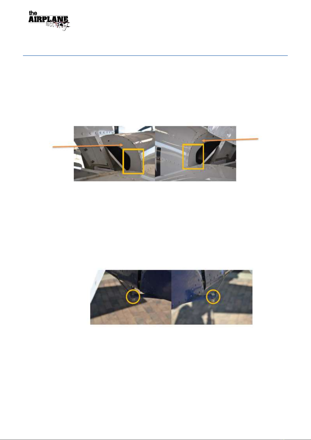
19. Place skin (4) onto the fuselage and cleco it in place by placing clecos in every second hole.
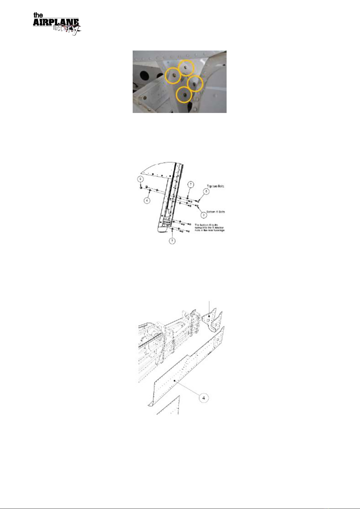
20. Rivet each hole with 3.2 mm domed aluminium rivets. It should be noted that with reference to the above
picture, the rivets in the red boxes should be rivets of 4 x 10 mm domed aluminium rivets, the exact place
of these rivets can be found with reference to the rib 601 & bracket assembly instruction page, and these
parts are labelled 3 & 4.
21. Remove all the clecos and rivet all the open holes where the clecos were. Ensure the correct rivets are
used in the correct places, refer to step 20.
22. Attach the horizontal stabiliser to the fuselage by means of tightening all 8 of its bolts to the mounting
brackets of the fuselage. These bolts need to be torqued to a value of 2.0 – 2.7 NM or 1.475 – 1.991 ft.lb
and torque seal applied over all 8 of these bolts.
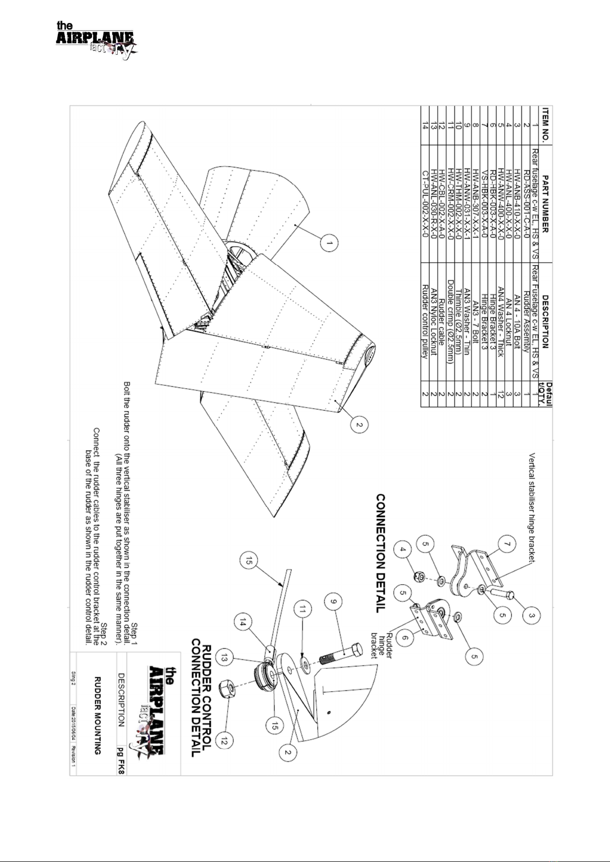
23. Attach the vertical fin by means of tightening all 12 bolts to the mounting brackets on the fuselage. These
bolts are to be torqued to the value of 2.0 – 2.7 NM or 1.475 – 1.991 ft.lb and torque seal applied over all
12 of these bolts.
24. Attach the rudders by means of tightening all 3 bolts through the rudder hinges. These 3 bolts should be
torqued to the value of 2.0 – 2.7 NM or 1.475 – 1.991 ft.lb and torque seal applied to all 3 bolts.
25. Connect the strobe light wire and verify that the strobe is serviceable.
26. Using the two 3/8” spanners attach the rudder cables by means of tightening both bolts at the connection
points. These bolts need to be torqued to the value of 2.0 – 2.7 NM or 1.475 – 1.991 ft.lb and torque seal
applied over these bolts.
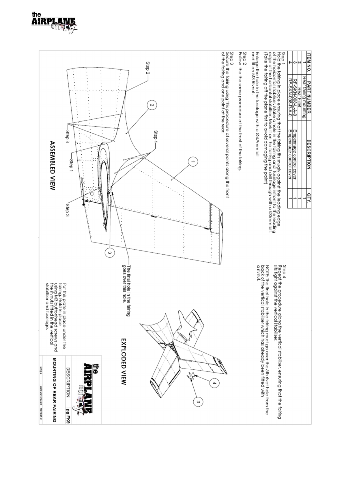
27. Attach the empennage fairing by means of tightening all the screws using a 2 mm Allen key.

The Airplane Factory
Manufacturing Organization DC-SBU-003-X-X-1
Service Bulletin Issue 1, 20/11/2015 Page no: 5
Figure 1: Mounting of rear fairing

The Airplane Factory
Manufacturing Organization DC-SBU-003-X-X-1
Service Bulletin Issue 1, 20/11/2015 Page no: 6
Figure 2: Rudder Mounting

The Airplane Factory
Manufacturing Organization DC-SBU-003-X-X-1
Service Bulletin Issue 1, 20/11/2015 Page no: 7
Figure 3: Mounting the vertical stabiliser

The Airplane Factory
Manufacturing Organization DC-SBU-003-X-X-1
Service Bulletin Issue 1, 20/11/2015 Page no: 8
Figure 4: Fitment of horizontal stabiliser

The Airplane Factory
Manufacturing Organization DC-SBU-003-X-X-1
Service Bulletin Issue 1, 20/11/2015 Page no: 9
Figure 5: Fit upper longerons and side skins

The Airplane Factory
Manufacturing Organization DC-SBU-003-X-X-1
Service Bulletin Issue 1, 20/11/2015 Page no: 10
Figure 6: Rib 6 assembly
Other Airplane Factory Aircraft manuals