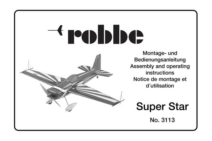
ROBBE Charter 3183 User manual

Assembly and operating instructions
Notice de montage et de pilotage
Istruzioni di montaggio e d’uso
Instrucciones de montaje y manejo
No. 3183

2

Charter
3
No.
3181
Specification
Wingspan: approx. 1470 mm
Overall length: approx. 1160 mm
Total surface area: approx. 41.4 dm2
All-up weight: min. 1800 g
Total surface area loading: min. 43.5 g / dm2
Please refer to the separate sheet for details of essential
accessories not included in the kit.
See the main robbe catalogue for information on tools and
aids to building.
Sequence of assembly
Before starting construction please study the plans, the illu-
strations and the associated brief instructions, together with
the Parts Lists, so that you have a clear understanding of
each stage of assembly.
The numbering of the Parts Lists is arranged to reflect the
sequence of assembly.
Key to the letters preceding the numbers in the Parts
Lists:
F = Wing (Flaeche)
R= Fuselage (Rumpf)
E = Electric power system
V = Glow power system (Verbrenner)
H = Main undercarriage (Hauptfahrwerk)
RC = Receiving system, final work
The model must be built on a perfectly flat building board.
Lay the appropriate plan on the board, tape it down, then
cover it with clear plastic film to prevent the parts sticking
to the drawing.
Paper is vulnerable to temperature fluctuations, with the
result that the plan may differ slightly in size from the pre-
cut and machined parts. If you notice a difference, always
work from the component sizes rather than the plan.
These instructions cover the construction of the basic wing
and fuselage structures, followed by the installation of the
power system. When the tail panels are complete, the indi-
vidual model components can be covered, and the main
undercarriage and receiving system installed.
We recommend that you install the selected power system
in the bare airframe, i.e. before covering. The components
should then be removed again before the covering is
applied. If you are an experienced modeller you may wish to
deviate from this general guideline.
Cutting stripwood and sheeting panels to size will leave
scrap material; don’t throw this away immediately, as you
may need it later for various small parts.
We recommend epoxy, robbe Speed Type 2 cyano-acrylate
(“cyano”) and fast-setting white glue for the glued joints on
this model; the instructions tell you which adhesive to use
at each stage.
Be sure to read and observe the instructions provided by
the individual adhesive manufacturers.
Allow all glued joints to harden fully before resuming work
on the model.
Directions such as “right-hand” are as seen from the tail
of the model, looking forward.
The Parts Lists
Parts marked “N.I.” are not included in the kit.
Model variants
The Charter may be flown with or without ailerons. In the lat-
ter case we recommend that you prepare the ailerons and
then disable them as described in the instructions; this allo-
ws you to connect them at a later date when your flying
skills improve.
For this model you have the choice between an electric
power system and a glowplug motor. Simply skip the stages
which do not apply to your chosen power system.
Radio control system
For this model you will need an RC system with at least four
channels and four servos.
For the electric version you will need an electronic speed
controller with a BEC function, whereas the glow version
requires one additional servo for the throttle.
Before you start construction you should consider carefully
how your receiving system components are to be installed
in the model.
If you wish to install a radio control system other than the
one we recommend, you can still follow the basic arrange-
ment shown, but you may have to make allowance for minor
differences in component sizes.
Before you start work on the model we recommend that you
connect the receiving system, set the transmitter sticks and
trims to centre, and switch the system on. This centres all
the servos.
Assembly and operating instructions

Charter
4
Parts List - basic wing structure
Part No. Description Material Dimensions No. off
F1Root facing rib Poplar ply 3 mm Laser-cut 2
F 2 Rib Poplar ply 3 mm Laser-cut 2
F 3 Rib Poplar ply 3 mm Laser-cut 2
F 4 Rib Poplar ply 3 mm Laser-cut 10
F 5 Rib Poplar ply 3 mm Laser-cut 2
F 6 Rib Poplar ply 3 mm Laser-cut 2
F 7 Rib Poplar ply 3 mm Laser-cut 2
F 8 Rib Poplar ply 3 mm Laser-cut 2
F 9 Tip rib Poplar ply 3 mm Laser-cut 2
F10 Tip block Balsa 8 mm Laser-cut 2
F11 Spar web Poplar ply 3 mm Laser-cut 2
F12 Servo plate Poplar ply 3 mm Laser-cut 2
F13 Aileron hinge spar Poplar ply 3 mm Laser-cut 2
F14 Bottom trailing edge sheeting Balsa 1.5 mm Laser-cut 2
F15 Top trailing edge sheeting Balsa 1.5 mm Laser-cut 2
F16 Top / bottom centre section sheeting Balsa 1.5 mm Oversize 2
F17 Bottom leading edge sheeting Balsa 1.5 x 85 x 740 Oversize 2
F18 Top leading edge sheeting Balsa 1.5 x 85 x 740 Oversize 2
F19 Aileron Balsa Shaped 2
F20 Wing dihedral brace Spruce 12 x 12 mm Overlength 1
F21 Wing locating peg Beech 5 mm Ø Overlength 1
F22 Leading edge Balsa 8 x 8 mm Overlength 2
F23 Spar Balsa 5 x 8 mm Overlength 4
F24 Aileron spar doubler Balsa 8 x 8 mm Oversize 2
F25 Aileron hinge Nylon 6
F26 Hinge peg (toothpick), N.I. Beech 2 mm Ø 12
F27 Servo extension lead, N.I. 2
Building the model
Stage 1, basic wing structure
Preparation
-Separate the plywood ribs F1 to F9 from the parent
sheets, and clean up the cut edges with glasspaper.
- The bottom leading edge sheeting F17 is supplied oversi-
ze; cut it to approximate size at this juncture.
- Tape the wing plan down on the building board and cover
it with clear plastic film.
No.
3181
Assembly and operating instructions
- The instructions describe the construction of one wing
panel. The second panel is assembled in exactly the same
way.
-Use cyano for all joints in this stage unless stated other-
wise.
Basic wing construction
Fig. 1
- Pin down the bottom leading edge sheeting F17 and the
bottom trailing edge sheeting F14.
Fig. 2
- Glue the bottom wing spar F23 to the bottom sheeting
panel F17 as shown in Section A-A. Check that the spar
is exactly straight. Place the rib F3 on the spar.
Figs. 3 and 4
- Glue the ribs F4 -F9 in place at the positions shown on the
plan; the ribs must be at right-angles to the building
board.

Charter
5
- The ribs F2 and F3 are different - don’t mix them up.
- Fit the spar web F11 and the rib F2 as shown on the plan.
Fig. 5
- Glue the spar web F11 and the rib F2 in place.
Fig. 6
-Glue the top wing spar F23 and the leading edge F22 to
the structure.
Fig. 7
- Cut the aileron spar doublers F24 to length and glue them
in place. Glue the aileron hinge spar F13 in the aileron
recess.
Fig. 8
- Pack up the bottom leading edge sheet panel F17 with
scrap strip wood so that it makes contact with the wing
ribs, as shown in Sections A-A and B-B. Clamp the shee-
ting to the leading edge using a spruce packing strip (n.i.)
and plenty of clothes pegs. The sheeting can now be
glued to the ribs and the leading edge. Check in particu-
lar that the sheeting makes good contact with the full
width of the leading edge. Allow the glue to set hard, then
cut off excess sheeting material where it projects beyond
the leading edge.
Fig. 9
- Bevel the bottom trailing edge sheet panel F14 to follow
the taper of the wing ribs, as shown in Section A-A; keep
the taper even over the full length of the wing panel.
Fig. 10
- Glue the top trailing edge sheeting F15 to the wing.
Fig. 11
-Note: the aileron servo leads can be extended using eit-
her the ready-made servo extension leads F27 or home-
made leads made up using suitable three-core flexible
cable; in the latter case cut off part of the servo lead with
the connector, and solder the extension lead between the
servo and the removed cable end. The illustrations show
the home-made version.
- Prepare the aileron servo lead with plenty of excess
length, and thread it through the wing ribs F3 to F5. Coil
up the excess, and stow it temporarily in the bay between
the ribs F2 and F3. Tape the servo lead in place to prevent
it falling out.
Fig. 12
- Check once more that the wing panel is absolutely
straight and flat, and is making good contact with the
building board; sight along it from the end to look for
warps.
- The top leading edge sheeting F18 can now be glued to
the structure, as shown in Sections A-A and B-B. This is
the procedure: apply fast-setting white glue to all the joint
surfaces, lay the sheeting panel on top and clamp it to the
top main spar with clothes pegs. Press the sheeting panel
down against the ribs and onto the leading edge, and pin
it to the leading edge using plenty of modelling pins.
Fig. 13
-Allow the glued joints to harden fully, and only then remo-
ve the clothes pegs and the pins.
Fig. 14
- Cut the top centre section sheeting panels F16 to size,
trim them carefully to fit, and glue them over the bay bet-
ween the ribs F2 and F3.
Fig. 15
- Remove the wing panel from the building board, and fit
the bottom centre section sheeting F16 in the same way.
Fig. 16
- Glue the servo plate F12 in the wing as shown.
Fig. 17
-Sand the sheeting and the leading edge to the profiles
shown in Sections A-A and B-B. Take particular care to
maintain the correct airfoil at the leading edge.
- Sand back the excess sheeting and spar material where
it projects beyond the root rib and the tip rib.
Fig. 18
- Glue the wingtip block F10 to the tip rib, and round it off
as shown.
Fig. 19
- Cut the aileron F19 (taper-section balsa strip) to fit in the
recess in the wing, and sand it to fit snugly.
Fig. 20
- Draw a centreline along the front face of the aileron F19.
-Sand the leading edge to a double-sided bevel, symme-
trically about the marked centreline, as shown in Section
B-B.
Fig. 21
- Mark the position of the hinge slots F25 on the leading
edge of the aileron, working from the pre-cut slots in part
F13. Cut the slots in the aileron, and continue the pre-cut
slots in part F13 through the 8 x 8 mm balsa strip
doublers.
Fig. 22
- Attach the aileron temporarily using three flat hinges, and
check that it moves freely up and down.
- Don’t glue the hinges in place at this stage.
Figs. 23, 24
- Drill 2 mm Ø holes through the hinges and the doublers
as shown, and fit short lengths of 2 mm Ø beech dowel
(toothpicks) in the holes to prevent them pulling out.
- Assemble the second wing panel using exactly the same
procedure, but “handed” (mirror image).
Assembly and operating instructions No.
3181

Charter
6
3181
No.
Stage 2, joining the wing panels
- White glue should be used for this stage.
- The following parts are required to join the wings: the root
facing ribs F1, the 12 x 12 mm spruce wing dihedral brace
F20 and the 5 mm Ø beech dowel locating peg.
- Start by assembling the wing panels “dry” (no glue) to
check that everything fits snugly.
Fig. 25
- Glue together the two root facing ribs F1 with their edges
flush, at the same time gluing the dowel F21 in place cen-
trally.
Parts List -basic fuselage structure
Part No. Description Material Dimensions No. off
R1Fuselage side Poplar ply 3 mm Laser-cut 2
R 2 Wing saddle doubler Poplar ply 3 mm Laser-cut 2
R 3 Former Poplar ply 3 mm Laser-cut 1
R 4 Former Poplar ply 3 mm Laser-cut 1
R 5 Sub-former Poplar ply 3 mm Laser-cut 1
R 6 Former Poplar ply 3 mm Laser-cut 1
R 7 Servo plate Poplar ply 3 mm Laser-cut 1
R 8 Front wing locating piece Poplar ply 3 mm Laser-cut 1
R 9 Front wing locating piece Poplar ply 3 mm Laser-cut 1
R10 Rear wing screw support Poplar ply 3 mm Laser-cut 1
R11 Rear wing screw support Poplar ply 3 mm Laser-cut 1
R12 Fuselage bottom Poplar ply 3 mm Laser-cut 1
R13a Bottom doubler Poplar ply 3 mm Laser-cut 1
R13b Bottom doubler Poplar ply 3 mm Laser-cut 1
R14 Front nose panel Poplar ply 3 mm Laser-cut 1
R15 Cabin glazing frame Poplar ply 3 mm Laser-cut 1
R17 Rear former Poplar ply 3 mm Laser-cut 1
R18 Rear former Poplar ply 3 mm Laser-cut 1
R19 Rear fuselage bottom Poplar ply 3 mm Laser-cut 1
R20 Fuselage top rear decking Poplar ply 3 mm Laser-cut 1
R21 Fuselage top rear decking Poplar ply 3 mm Laser-cut 1
R28 Fuselage longeron Balsa 4 x 4 mm Overlength 4
R29 Snake sleeve / pushrod (one Z-bend) Nylon Ready made 2 each
R30 Cabin glazing Hard PVC Ready made 3
R31 Tailskid Poplar ply 3 mm Laser-cut 1
Assembly and operating instructions
Figs. 26 to 28
- Insert the spruce dihedral brace F20 in one wing panel,
and fit the two ribs F1 and the beech dowel F21 on it, fol-
lowed by the second wing panel: the wing panels should
meet accurately in the centre, without gaps, and must not
be out of line or twisted relative to each other.
- When you are satisfied that this is the case, dismantle the
parts again, apply plenty of white glue to all the joint sur-
faces, and re-assemble the components in a single pro-
cedure. Ensure that parts F11 and F20 are glued securely
over their full area. Clamp the wing panels together in the
centre and at the trailing edge, and leave the glue to set
hard.
- When the joints are cured, sand the whole wing overall to
obtain a smooth, even finish.
- Drill a 6 mm Ø hole in the root ribs F1 at the marked point
for the wing retainer screw.
The basic wing structure is now complete. Work on it resu-
mes when the fuselage and tail panels have been built.

Charter
7
3181
No.
Stage 3, basic fuselage structure
Note: remember to prepare one right-hand and one left-
hand fuselage side (mirror-image pair).
Use cyano for all joints in this stage unless stated otherwi-
se.
Fig. 29
- Glue the wing saddle doublers R2 to the inside of the
fuselage sides R1. Take care to keep the edges flush.
Figs. 30 and 31
-Trim the balsa fuselage longerons R28 to fit and glue them
to the fuselage sides R1 in the positions shown on the
plan. Sand the longerons to a taper at the tail end of the
fuselage - see plan view.
Fig. 32
-Pin down one fuselage side R1 on the building board and
glue the formers R4 to R6 and the servo plate R7 to it, fit-
ting the tabs into the slots; keep them at right-angles to
the fuselage side.
Figs. 33 and 34
- Place the second fuselage side on the formers, checking
at the tail end that the parts are lined up correctly; the
fuselage sides must not be twisted or offset relative to
each other.
- Glue the nose former R3 in place.
Fig. 35
- Glue the second fuselage side in place, installing the wing
supports R8 to R11 at the same time.
Fig. 36
- The bottom panel R12 can now be glued to the undersi-
de of the fuselage: start by gluing the area between for-
mers R4 to R6 only.
Fig. 37
- Glue the fuselage bottom doublers R13a + R13b in place
over their full area.
Fig. 38
-Allow the glued joints to set hard, then curve the front part
of the bottom panel R12 down to meet the former R3, and
glue the parts together.
Fig. 39
- Glue the front nose panel R14 to the fuselage.
Stage 4 - electric power system
Part No. Description Material Dimensions No. off
R16 Former Poplar ply 3 mm Laser-cut 1
R22 Motor mount side fairing Balsa 8 mm Laser-cut 2
R23 Nose fairing Balsa 8 mm Laser-cut 1
R24 Upper motor mount Poplar ply 3 mm Laser-cut 1
R25 Motor mount side panel Poplar ply 3 mm Laser-cut 2
R26 Motor mount (A + B) Poplar ply 3 mm Laser-cut 1 each
R27 Lower motor mount Poplar ply 3 mm Laser-cut 1
Top motor mount sheeting Balsa 1.5 mm 1
E1 Electric motor, N.I. 1
E2 Motor retaining Screw, N.I. M3 x 6 4
E3 Speed controller,N.I. 1
E4 Battery tray, long strip Balsa 8 x 8 x 200 mm 2
E5 Battery tray, support strip Balsa 8 x 5 x 200 mm 2
E6 Battery tray, rear cross-strip Balsa 8 x 8 x 60 mm 1
E7 Battery tray, front cross-strip Balsa 8 x 5 x 60 mm 1
E8 Flight battery, N.I. 1
E9 Velcro tape, N.I. 1
Assembly and operating instructions
- Glue the windscreen frame R15 in place.
Fig. 40
- Pull the fuselage sides together at the tail, taking care to
keep the fuselage symmetrical.
-Fit the rear fuselage formers R17 and R18, and glue the
joints.
- Glue the rear fuselage bottom panel R19 in place.
- Glue the top rear decking pieces R20 and R21 to the fuse-
lage.
Figs. 41 and 42
-Cut the rudder and elevator snake outers R29 to length,
and fit them in the fuselage. Slip the pre-formed pushrods
into the sleeves to stiffen them.
Fig. 43
- Epoxy the snake outers to the fuselage sides at the tail
end only; the front ends are not glued until the servos and
pushrods have been installed.
Fig. 44
- Trim the tailskid R31 to fit, but do not glue it in place; the
skid is fitted permanently after the model has been cover-
ed.

Charter
8
3181
No.
Figs. 45 and 46
- Assemble the motor mount from the parts R16, R24 to
R27 and glue the joints. Note that the appropriate motor
bulkhead R26 A or B should be selected to suit the elec-
tric motor you intend to install.
Fig. 47
-Fit the projecting lugs of the motor mount assembly
through the slots in the nose former R3, and glue the
joints well.
Fig. 48
- Glue the nose fairing panels R22 to both sides of the
motor mount.
-Glue the motor mount nose fairing R23 in place.
- Fill in the top of the motor mount with 1.5 mm balsa sheet.
Fig. 49
- Round off the fuselage nose, sand the entire fuselage
overall, and round off the corners neatly.
Figs. 50 and 51
- Solder the appropriate connectors to the cables attached
to the electric motor E1, as described in the instructions
provided with the motor.
- Install the motor from the underside, and fit the motor
retaining screws E2 temporarily.
Fig. 52
-Solder matching connectors to the cables attached to the
speed controller (for the motor and the flight battery), as
described in the instructions supplied with the controller.
Figs. 53 and 54
- Install the speed controller E3 and attach it to the fusela-
ge side using Velcro tape. Run the motor cables through
the large opening into the motor compartment.
Fig. 55
- Connect the speed controller to the motor, connecting
like cable colours.
Fig. 56
- Run the speed controller cables for the flight battery back
into the fuselage.
Fig. 57
- Cut the balsa strips E4 to E7 to length to form the battery
tray, and glue the parts together at right-angles. Note: if
you are using a battery other than the recommended
type, you may need to adjust the width between the rails
to suit the pack.
Fig. 58
- Fit the battery tray in the fuselage with the front cross-
piece E7 resting against the former R4.
- Glue the battery tray in the fuselage.
Fig. 59
- Solder matching connectors to the flight battery E8.
-Place the battery in the battery tray and wrap a strip of
Velcro tape E9 round the pack and the tray to secure it.
- Do not connect the battery to the speed controller at
this stage.
Assembly and operating instructions
Stage 5 - glowplug power system
Part No. Description Material Dimensions No. off
R16 Former Poplar ply 3 mm Laser-cut 1
R22 Motor mount side fairing Balsa 8 mm Laser-cut 2
R23 Nose fairing Balsa 8 mm Laser-cut 1
R25 Motor mount side panel Poplar ply 3 mm Laser-cut 2
R26V Nose bulkhead (glow version) Poplar ply 3 mm Laser-cut 1
R27V Lower motor bulkhead (glow version) Poplar ply 3 mm Laser-cut 1
V 1 Captive nut M3 4
V 2 Motor mount, N.I. 1
V3Motor mount retaining screw, N.I. M3 x 18 4
V 4 Glowplug motor and silencer, N.I. 1
V5Motor screws and nuts, N.I. M3 x 25 4
V 6 Balsa strip 1.5 mm 1
V 7 Snake outer and pushrod 1 each
V8 Threaded coupler and locknut 2
V 9 Plastic clevis 1
V10 Throttle servo, N.I. 1
V11 Clevis 1
V12 Fueltank complete, N.I. 1
V13 Fuel tubing, N.I. 2
V14 Strip Balsa 8 x 8 mm 1

Charter
9
3181
No.
Fig. 60
- Construct the fuselage nose assembly for the glow versi-
on from parts R16, R25, R26V and R27V, and glue the
joints soundly.
Fig. 61
- Glue the nose assembly to the fuselage.
-Glue the side fairings R22 and the nose fairing R23 in
place as shown. Relieve part R23 to follow the shape of
the former R26V.
-Sand the entire fuselage nose area to a neat, rounded
shape.
Fig. 62
- Press the four captive nuts V1 into the holes in the nose
bulkheads from the rear.
Fig. 63
- Fix the motor mount V2 in place using the screws V3.
Figs. 64 and 65
-Place the motor V4 on the mount, and mark a clearance
line for the silencer in the right-hand side and at the fuse-
lage nose. Cut away the cowl to clear the silencer.
- Cut the notch at the front for the throttle arm as shown.
- Place the motor on the mount arms again, mark the posi-
tion of the holes for the retaining screws using the motor
lugs as a guide, and drill them 3 mm Ø.
- Temporarily install the motor by fitting the screws V5
through the motor lugs and the mount arms.
- Mount the silencer on the motor, and check that there is
adequate clearance between it and the fuselage.
- Seal the opening in the front part of the fuselage with a
piece of cross-grained 1.5 mm balsa sheet V6.
Fig. 66
-Mark the position of the hole for the throttle linkage in the
nose bulkhead, in line with the throttle arm, and drill it 3.5
mm Ø.
- Cut the throttle snake outer V7 to a length of about 240
mm, fit it through the hole and glue it to the nose
bulkhead.
- Solder the threaded coupler V8 to the end of the throttle
pushrod, and screw the plastic clevis V9 on the end. Slip
the pushrod through the snake outer and connect the pla-
stic clevis to the throttle arm.
Fig. 67
- Press the rubber grommets and metal spacers into the
mounting lugs of the throttle servo V10, and install it in the
servo tray.
- Cut down the servo output arm as shown.
- Move the servo to the “full-throttle” position from the
transmitter, and open the carburettor barrel fully.
- Cut the pushrod to the correct length, solder the threaded
coupler V8 to the end and screw an M2 locknut on it.
Connect the pushrod to the servo using a clevis V11.
Figs. 68 and 69
- Install the two nipples in the fueltank V12 as described in
the instructions supplied with it.
- The tank is installed in the fuselage and packed round
with pieces of foam to hold it in position; note that the
foam has to be positioned before the tank is fitted.
- Cut overlength pieces of fuel tubing V13 (Fig. 70) and
connect them to the fueltank nipples. Stick a piece of
insulating tape to the fuel line which is connected to the
clunk pick-up.
- Remove the motor.
- We recommend that you seal the tank compartment
and the motor bay with sanding sealer or clear lacquer
to protect it from fuel.
- Place the fueltank in the fuselage, routing the fuel lines
through the large hole in the nose bulkhead.
- Cut a piece of 8 x 8 mm balsa strip V14 to length and
install it across the fuselage as shown, to hold the fuel-
tank in position. Tack the strip in place with just a few
drops of cyano so that you can remove it and withdraw
the fueltank at any time for maintenance.
Fig. 70
- Install the motor, and cut the fuel lines to the correct
length. When the motor has been installed permanently,
the fuel feed line (marked with tape) is connected to the
carburettor nipple.
-Remove the motor again. The motor should not be instal-
led permanently until the model has been covered.
Assembly and operating instructions
Stage 6 - tailplane and fin
Parts List for the tail panels
Part No. Description Material Dimensions No. off
L1Fin strake Balsa 6 mm Laser-cut 1
L 2 Fin Balsa 6 mm Laser-cut 1
L3 Rudder Balsa 6 mm Laser-cut 1
L4 Tailplane centre section Balsa 8 mm Laser-cut 1
L5 Elevator Balsa 8 mm Laser-cut 1
L6 Tailplane cross-piece Balsa 8 x 3 mm As plan 12
L7 Leading edge / trailing edge Balsa 8 x 8 mm As plan 5
L 8 Gusset Poplar ply 3 mm Laser-cut 2
L9 Hinge Nylon - Ready made 8
L10 Hinge peg (tooth-pick), N.I. Beech 2 mm Ø 8

Charter
10
3181
No.
The tailplane and fin are built directly over the film-covered
plan.
Use cyano for all joints unless stated otherwise.
Fig. 71
-Glue the fin strake L1 to the fin L2.
-Round off the fin L1 + L2 and the rudder L3, and sand
them to the correct profile as shown in cross-section B-B.
- Sand the whole length of the rudder leading edge to a
double-sided bevel.
Fig. 72
- Cut the three slots for the rudder hinges L9 and check
that the hinges fit snugly. Insert the hinges and fit the
hinge pegs L10 to secure them. Temporarily attach the
rudder to the fin by inserting the hinges “dry” (no glue).
Fig. 73
- Pin down the tailplane centre section L4 over the film-
covered plan, and cut the leading edge pieces, the full-
length trailing edge and the tailplane tips from the balsa
strip L7, working from the plan. Glue these parts to L4
directly over the plan.
Fig. 74
- Cut the tailplane cross-pieces L6 from the 3 x 8 mm balsa
strip supplied, trim them carefully to fit as shown on the
plan, and glue them to the structure.
- Glue the gussets L8 in the corners of the tailplane.
Figs. 75 and 76
- Allow the joints to set hard, then remove the tailplane from
the plan. Sand the tailplane and the elevator L5 to the
shape shown in section A-A, and sand the elevator to the
correct profile.
- Sand the full length of the elevator leading edge to a
double-sided bevel.
Fig. 77
- Cut the five slots for the elevator hinges L9 and check that
the hinges are a snug fit. Insert the hinges, and fit the
hinge pegs L10 to secure them. Temporarily attach the
elevator to the tailplane by inserting the hinges “dry” (no
glue).
Stage 7 - assembling the model, covering
Parts required
M6 captive nut
M6 x 35 plastic screw
Fig. 78
- Place the wing on the fuselage and position it exactly
central and “square” to the fuselage centreline. Mark the
position of the wing retaining screw on the screw support
R10 / R11 by twisting a drill through the hole in the ribs
F1. Remove the wing and drill the hole 6 mm Ø.
Figs. 79 and 80
-Open up the hole in the support to 7 mm Ø. Fit the capti-
ve nut from underneath and press it into the wood using
apair of combination pliers. Apply epoxy to the edges of
the nut to prevent it falling out.
Fig. 81
- Fix the wing to the fuselage using the M6 x 35 plastic
screw.
- Fit the tailplane into its slot and set it exactly central. Mark
the exact position on both sides of the tailplane, top and
bottom.
-Check its position: X right = X left.
- Fit the fin in its slot and check that it is exactly at right-
angles to the tailplane.
- The model components are now ready for covering.
General notes on covering
- We recommend that you cover the model with Super
Solarfilm. Please read the instructions supplied with the
film.
- Note: it is always best to cover all the components sepa-
rately, and join them later.
Figs. 82 and 83
- Slit the covering film to expose the hinge slots in the con-
trol surfaces. Insert the hinges in the slots and secure
them with a drop of cyano each. Check that the rudder
and elevator move freely to both sides of neutral.
- We recommend that you fit retaining pegs (tooth-picks)
through the hinges in the control surfaces for additional
security.
Fig. 84
-The joint areas of the fin must be left free of film.
Fig. 85
- Do not cover the joint areas of the tailplane.
-Attach the elevator permanently to the tailplane, as
described for the rudder.
Fig. 86
-Fuselage: apply the covering film to the whole of the fuse-
lage, including the window frames, the undercarriage
channels and the slots for the tailplane and fin. The film
can then be cut away to free up these openings; take care
not to cut into the wood.
Fig. 87
-Glue the tailskid permanently to the fuselage.
Figs. 88 and 89
- If you do not wish to use the ailerons initially, they should
still be attached to the wings using the hinges as already
described.
Assembly and operating instructions

Charter
11
3181
No.
- Tape or hold each aileron at the neutral position, and drill
a2mmØhole through the wingtip and into the control
surface. Push a retaining peg (tooth-pick -N.I.) into the
hole to fix the aileron in place.
Fig. 90
-Sand back the end of the tooth-pick flush with the wing-
tip. Repeat with the second aileron.
Figs. 91 and 92
- The ailerons can now be covered as part of the wing. If
you later wish to use the model with aileron control, sim-
ply slit the film and saw through the tooth-picks, and the
ailerons are ready for the linkages.
Fig. 93
- If you have fitted working ailerons, the servo extension
leads should be routed out of the wing when covering is
complete:
- This is done by drilling a hole in the bottom wing sheeting
close to the leading edge, between ribs F2 and F3, so that
the aileron servos can be threaded through them when
the wing has been covered.
- Apply a little cyano to the edge of the holes to harden the
material.
- Cover the ailerons separately, and only then attach them
to the wings using the hinges. Secure each hinge with a
drop of cyano, and fit tooth-pick pegs when the glue is
hard for additional security.
Stage 8 - the main undercarriage
Parts List
Part No. Description No. off
H1 Main undercarriage unit, 4 mm Ø 1
H2 Wire brace, 3 mm Ø 1
H3 Oval sleeve 2
H4 Undercarriage saddle clamp 4
H5 Self-tapping screw, 2.9 Ø x 9.5 8
H6 Wheel 2
H7 Collet and grubscrew 4
Figs. 94 and 95
- Fit the oval sleeves H3 on the main undercarriage unit H1
and the brace H2 to join them.
- Remove the film covering over the undercarriage chan-
nels in the underside of the fuselage.
- Fit the undercarriage in the slots, drill 2 mm Ø pilot-holes
for the retaining screws, and fix the undercarriage to the
fuselage using the saddle clamps H4 and the self-tapping
screws H5.
- Check the alignment of the main undercarriage, then sol-
der the wire legs to the oval sleeves, taking care to pro-
duce strong joints.
Figs. 96 and 97
- Fit the wheels H6 on the axles and secure them with the
collets H7. Check that the wheels rotate freely.
Stage 9 - installing the servos, final work
Parts List
Part No. Description No. off
RC1 Rudder / elevator servo, N.I. 2
RC2 Control surface horn, complete 2 (4)
RC3 Threaded coupler and locknut 2 (4)
RC4 Clevis 2 (4)
RC5 Balsa strip, 4 x 4 mm 2
RC6 Aileron servo, N.I. 2
RC7 Aileron pushrod 2
RC8 Receiver, N.I. 1
RC9 Strain relief, N.I. 1
RC10 Switch harness, N.I. 1
RC11 Receiver battery, N.I. 1
-Remove the output arms or discs from all the servos.
Figs. 98 and 99
- Press the rubber grommets and metal spacers into the
mounting lugs of the servos RC1, and set them to neutral
from the transmitter.
- Install the rudder and elevator servos RC1 in the servo
plate in the fuselage.
- Cut down the servo output levers as shown, connect the
pre-formed end of the pushrods to them, and slip the
pushrods into the outer sleeves in the fuselage.
- Fit the output levers on the servos and secure them with
the servo output screws.
-Trim the strip RC5 to fit across the fuselage, and glue it to
the former R6 with the snake outers resting on it. Glue the
pushrod outer sleeves securely to the strip.
Figs. 100 and 101
- Position the horns RC2 on the control surfaces, exactly in
line with the pushrods. Note their position relative to the
hinge pivot axis “D”.
- Mark the position of the horn retaining screws and drill
them 2 mm Ø. Fix the horns in place using the M2 screws
and the spreader plates supplied.
- Tape or pin the control surfaces at the centre position.
- Cut the pushrods to correct length and fit the threaded
couplers on the cut ends. Fit a locknut on each threaded
coupler. Place a piece of scrap wood under the pushrods
prior to soldering the joints, to avoid splashes of solder or
flux damaging the covering film.
- Solder the joints, then screw the clevises on the threaded
couplers and connect the control surfaces.
Aileron servos (optional)
Figs. 102 and 103
- Locate the aileron servo wells in the wings and remove
the covering film over them.
-Connect the servos to the extension leads in the wings,
and fit them in the servo wells. Drill 1.5 mm Ø pilot-holes
and screw the servos to their mounts.
- Cut down the servo output levers as shown, and fit them
on the servos at 90° to the line of the pushrods. The servo
output arms must lie parallel to the aileron hinge pivot
axis.
- Make up the aileron pushrods and connect them to the
servo output arms. Position the horns on the ailerons in
line with the pushrods, remembering to position the linka-
Assembly and operating instructions

Charter
12
3181
No.
ge hole at right-angles to the hinge pivot axis. Mark the
position of the retaining screw holes and drill them 2 mm
Ø.
- Fix the horns to the ailerons and connect the pushrods.
- Remove the covering film over the inboard holes in the
underside of the wing, and run the aileron servo extensi-
on leads out through them.
-Snip off excess screw length at all the horns, and file back
the cut ends flush with the spreader plates.
Fig. 104,
installing the receiver (electric version)
- Connect the receiving system (RC8), ready for use. A Y-
lead is normally required to connect the aileron servos. If
you wish to connect the aileron servos to two separate
receiver channels, use two short servo extension leads.
- Unwind the flexible wire aerial attached to the receiver
RC8.
-Fix the receiver in the fuselage using Velcro tape.
-Make the strain relief RC9 from a spare piece of servo
output arm, and thread the receiver aerial through it.
Fig. 105
- Drill a 3 mm Ø hole in the fuselage top decking, run the
aerial through it, and attach the end to the fin using adhe-
sive tape.
Fig. 106
Receiver, receiver battery and switch harness (glow versi-
on)
- Cut a piece of foam to shape to accept the receiver and
receiver battery as shown; this is required to absorb the
vibration caused by the glow motor.
Figs. 107 and 108
- Install the switch harness RC10 and the receiver battery
RC11. Connect the complete receiving system, ready to
work. Deploy the receiver aerial using the method descri-
bed for the electric version - see Figs. 104 and 105.
Final work
Fig. 109
- Glue the side glazing panels and the front screen to the
fuselage using contact cement.
Fig. 110
-Fit the propeller driver on the electric motor, followed by
the propeller and spinner.
Glow version - see Fig. 70
- Install the motor and silencer permanently, and connect
the throttle linkage.
- Connect the fuel lines.
- Install the propeller and spinner.
Balancing
-Mark the CG position on both sides of the fuselage; it
should be 73 mm aft of the wing root leading edge, i.e.
exactly under the main spar - see side elevation on the
fuselage plan.
- Attach the wing to the fuselage and assemble the model
completely, ready to fly. Mark the CG position on both
sides of the fuselage.
- Support the model under the wings at the marked points
using your index fingers, held close to the fuselage.
Ideally the model will now balance level, with the nose
angled slightly down.
- If necessary, move the flight battery or the receiver battery
forward or aft slightly to correct any discrepancy.
Lead ballast can be fitted to correct the CG, but only if re-
positioning the battery is not sufficient. Fix any ballast
securely, so that there is no chance of it shifting in flight
and altering the model’s balance.
Fig. 111 - checking the working systems
-Set the transmitter sticks and trims to centre.
- Switch the transmitter on, then switch the receiving
system on.
- All the model’s control surfaces should now be at centre
(neutral). If this is not the case, screw the clevises in or out
on the threaded couplers to correct.
- Stand behind the model, and move the rudder stick to the
right: the rudder should also deflect to the right.
-Pull the elevator stick back towards you, and the trailing
edge of the elevator should rise.
- Move the aileron stick to the right, and the trailing edge of
the right aileron should rise, the left aileron fall.
- If any function works the wrong way round, correct it
using the servo reverse facility on your transmitter.
- If necessary, adjust the servo travels using the servo tra-
vel limit function on your transmitter.
Fig. 112 - checking the electric power system
-Caution: adjust the motor control system so that the
motor cannot start running when the throttle stick is at the
idle end-point; see the speed controller instructions for
details.
-Check the direction of rotation of the motor: when seen
from the front, the propeller shaft must rotate anti-clock-
wise. If this is not the case (e.g. if you are using compo-
nents other than those recommended), swap over two of
the motor wires to reverse the direction of motor rotation.
Checking the glow motor power system
- Check the throttle function at both end-points as follows:
move the throttle trim to the forward end-point and apply
full throttle. The carburettor barrel should now be com-
pletely open. If the servo runs to the opposite end-point,
correct it using the servo reverse facility on your transmit-
ter.
- At the idle end-point the throttle barrel should be almost
completely closed, leaving a gap about 1 mm wide. Now
move the throttle trim right back (towards you), and the
barrel should close fully: this will stop the motor. Before
you fly the model for the first time, check these settings
with the glow motor running.
Assembly and operating instructions

Charter
13
3181
No.
- Note: the throttle pushrod must not be under tension
(servo stalled) at either end-point, as this causes the
servo to draw a constant heavy current. If necessary,
adjust the pushrod travel by connecting it to a different
hole at the servo or the throttle lever.
Refueling
-To fill the fueltank disconnect both fuel lines, and fill the
tank using the feed line (the one connected to the carbu-
rettor nipple). The pressure line (normally connected to
the silencer) serves as the overflow.
- Running the motor: the glow motor must be properly run-
in before you fly the model for the first time. Adjust the
motor so that it runs smoothly and reliable at all throttle
settings. Repeat the check with the model’s nose held
vertically up and down; the motor’s speed should not
vary.
- Caution: whenever you are adjusting or otherwise wor-
king on the model, keep well clear of the rotational
plane of the propeller - injury hazard. By the same token
ensure that no persons are standing in front of the
model when the motor is running.
Test-flying, flying notes
- Before the first flight please read the sections in the
“Safety Notes” entitled “Routine pre-flight checks” and
“Operating the model”.
- For your first few flights please wait for a day with no
more than a gentle breeze.
- A good flying site consists of a large, flat, open grassy
field. Keep well clear of high-tension overhead cables,
busy roads, residential areas, airfields and other
obstacles.
-Repeat the check of the working systems.
-If you are flying the model from a hand-launch, ask an
experienced friend to launch for you. He should be confi-
dent of giving the aeroplane a firm launch.
- The model must be launched straight into any breeze.
- Switch the motor on and give the Charter a firm launch,
directly into wind, with the fuselage and wings level.
- Keep the aeroplane flying straight and level at first; do not
attempt to turn it while you are flying close to the ground.
-Adjust the trims if necessary until the model is climbing
steadily in a straight line.
-Check the model’s reaction to control commands; you
may need to increase or reduce the control surface travels
after the first flight in order to suit your style of flying.
- Check the model’s stalling speed at a safe height.
- Initiate the landing approach with plenty of speed.
- If you had to adjust the trims during the first flight, adjust
the pushrod lengths once the model is safely back on the
ground, so that the trims can be returned to centre. This
ensures that full trim travel is available in both directions
for subsequent flights.
- The model is also capable of taking off from the ground.
The take-off must be carried out exactly into wind.
-Carry out a few ground-roll tests before the first take-off,
so that you have a clear idea how the model behaves on
the ground.
- Once you feel confident with its ground handling, place
the model on the runway facing directly into wind.
- Open the throttle steadily and continuously to the full-
throttle point, allow the model to pick up plenty of speed,
then apply gentle up-elevator to lift off - taking care
not to stall it. Adjust the trims immediately if necessary.
robbe Modellsport GmbH & Co. KG
We reserve the right to alter technical specifications.
Assembly and operating instructions

Charter
14
Caractéristiques techniques
Envergure : approx. 1 470 mm
Longueur totale : approx. 1 160 mm
Surface alaire totale : approx. 41,4 dm2
Poids en ordre de vol : à partir de 1 800 g
Charge alaire totale : à partir de 43,5 g/dm2
Les accessoires indispensables à la mise en ?uvre du
modèle, non contenus dans la boîte de construction, sont
présentés sur le feuillet joint.
Outillage et accessoires de montage, cf. catalogue
général robbe
Généralités concernant le déroulement de la construction
Avant d'entreprendre la construction du modèle, observer
les plans de construction et lire les textes de la notice au
regard des illustrations et des listes de pièces afin de vous
forger une vue d'ensemble des différentes étapes de la con-
struction.
Les listes de pièces sont classées en fonction d’une
séquence numérique et nom en fonction de leur séquence
d’intervention dans le montage.
Les lettres en préfixe des numéros dans la liste des piè-
ces ont la signification suivante:
F=aile
R=fuselage
E = entraînement électrique
V = entraînement thermique
H=atterrisseur principal
RC = ensemble de réception, travaux de finition
Procéder à l’assemblage sur un chantier parfaitement plan
sur lequel sera fixé le plan de construction approprié.
Recouvrir le plan d’une feuille de plastique transparent afin
de lui éviter toute détérioration due à la colle.
Le papier subit l’influence des variations de température.
C’est pourquoi le plan de construction et les éléments
fraisés sont susceptibles de présenter de très légères dif-
férence de longueur. Dans ce cas, ce sont les pièces en
bois qui doivent servir de référence.
La notice présente une description du gros œuvre de l’aile
et du fuselage et ensuite la mise en place de l’entraînement.
Après avoir réalisé la structure des empennages, intervient
l’entoilage des divers éléments, puis le montage de l’atter-
risseur principal et enfin la mise en place de l’ensemble de
radiocommande.
Nous recommandons d’installer l’entraînement suggéré
dans la structure du fuselage puis de redémonter ensuite
les différents éléments avant de réaliser l’entoilage. En fon-
ction du niveau de l’expérience de chacun dans la con-
struction de modèles, il est possible de procéder différem-
ment.
Conserver les chutes baguettes et de planchettes de coff-
rage, ils sont susceptibles d'être utilisés pour la réalisation
de petits éléments.
Pour les travaux d’encollage, utiliser de la colle époxy et de
la colle cyanoacrylate robbe Speed Type 2, de même que
de la colle blanche à séchage rapide.
Observer le mode d'emploi des produits fourni par les fabri-
cants.
Bien laisser sécher tous les points de collage.
Les indications directionnelles telles que „droite“, par
exemple, sont à considérer dans le sens du vol.
Instructions concernant les listes de pièces
Les éléments pourvus de la mention “n.c.” ne sont pas con-
tenus dans la boîte de construction.
Variantes de construction
Il est possible de construire et de faire voler le modèle avec
et sans ailerons. Il est recommandé dans tous les cas de
préparer les ailerons et de les mettre de côté. On a ainsi la
possibilité, avec l’amélioration de ses connaissances des
techniques de pilotage d’installer les ailerons ultérieure-
ment.
Pour l’entraînement, il est possible d’installer un moteur
électrique ou un moteur thermique. En fonction de l’entraî-
nement prévu, sauter le stade de montage qui ne convient
pas.
Consignes concernant l'ensemble de radiocommande
Comme ensemble de radiocommande, il faut disposer d’un
ensemble à quatre voies avec quatre servos.
Avec un entraînement électrique, il faut utiliser un variateur
de vitesse électronique avec une fonction d’alimentation
directe de l’ensemble de réception (BEC) et avec l’entraîne-
ment thermique, il faut disposer d’un servo supplémentaire.
Avant d'entreprendre la construction du modèle, il est
rationnel de disposer de l'ensemble de radiocommande afin
d'en évaluer les possibilités d'implantation.
Si vous souhaitez utiliser un autre ensemble de radiocom-
mande que celui que nous recommandons, ajustez de
vous-même les nuances de cote en liaison avec le schéma
d'implantation. À vous d'ajuster les différences de cotes.
Avant de commencer la construction, amener les servos au
neutre à l'aide de l'ensemble de radiocommande (manches
et dispositifs de réglage de précision (trim) en position
médiane).
Notice de montage et d’utilisation réf.
3181

Charter
15
Notice de montage et d’utilisation
Liste des pièces composant le gros œuvre de l’aile
N° Désignation Matériau Cotes Nbre
de pièce
F 1 nervure raccord bouleau 3 mm élément coupé au laser 2
F 2 Nervure bouleau 3 mm élément coupé au laser 2
F 3 Nervure bouleau 3 mm élément coupé au laser 2
F 4 Nervure bouleau 3 mm élément coupé au laser 10
F 5 Nervure bouleau 3 mm élément coupé au laser 2
F 6 Nervure bouleau 3 mm élément coupé au laser 2
F 7 Nervure bouleau 3 mm élément coupé au laser 2
F 8 Nervure bouleau 3 mm élément coupé au laser 2
F 9 nervure terminale bouleau 3 mm élément coupé au laser 2
F 10 bord marginal balsa 8 mm élément coupé au laser 2
F 11 coffrage angulaire bouleau 3 mm élément coupé au laser 2
F 12 planchette de servo bouleau 3 mm élément coupé au laser 2
F 13 traverse d’aileron bouleau 3 mm élément coupé au laser 2
F 14 coffrage de bord de fuite de l’intrados balsa 1,5 mm élément coupé au laser 2
F 15 coffrage de bord de fuite de l’extrados balsa 1,5 mm élément coupé au laser 2
F 16 coffrage intermédiaire intrados/extrados balsa 1,5 mm Découpe 2
F17 coffrage de bord d’attaque de l’intrados balsa 1,5x85x740 Découpe 2
F 18 coffrage de bord d’attaque de l’extrados balsa 1,5x85x740 Découpe 2
F19 ailerons balsa pièce façonnée 2
F20 raccord d’aile pin 12 x 12 mm Découpe 1
F21 raccord d’aile hêtre 5 mm rond Découpe 1
F22 bord d’attaque balsa 8 x 8 mm Découpe 2
F23 longerons balsa 5 x 8 mm Découpe 4
F24 renfort de traverse d’aileron balsa 8 x 8 mm Découpe 2
F25 charnières d’aileron nylon 6
F26 cheville de charnière (cure-dent), n.c. hêtre Ø 2 mm 12
F27 cordon rallonge de servo, n.c. 2
- La notice présente la description d’une seule demi-aile.
La seconde demi-aile sera construite de manière analo-
gue.
- En l’absence de mention contraire, coller avec de la colle
cyanoacrylate.
Gros œuvre de l’aile
Fig. 1
- Fixer les éléments de coffrage du bord d’attaque et du
bord de fuite de l’intrados F17, F14 avec des épingles.
Fig. 2
- Coller le longeron d’aile du bas F23 en fonction des indi-
cations de la coupe A-A sur le coffrage F17. Veiller à ce
que le longeron soit disposé de manière parfaitement rec-
tiligne. Mettre la nervure F 3 en place.
Fig. 3 et 4
- Coller les nervures F4 à F9 selon les indications du plan.
Les nervures doivent être mises en place de manière par-
faitement perpendiculaire au chanter de construction.
réf.
3181
La construction du modèle
Stade de montage 1, le gros œuvre de l’aile
Préparatifs
- Détacher les nervures en contreplaqué F1 à F9 des plan-
chettes de fabrication et en poncer les arêtes de coupe
avec du papier de verre fin.
- Couper avec une certaine marge les planchettes très lar-
ges de coffrage du bord d’attaque de l’intrados F17.
- Fixer le plan de construction sur le chantier et le recouvrir
d’un film plastique.

Charter
16
- Veiller à ne pas intervertir les nervures F2 et F3.
- Mettre la plaque de coffrage F11 et la nervure F2 en place
selon les indications du plan.
Fig. 5
-Coller la plaque de coffrage F11 et la nervure F2.
Fig. 6
- Coller le longeron d’aile du haut F23 et le bord d’attaque
F22.
Fig. 7
- Couper à la longueur indiquée et coller la baguette de
coffrage de la traverse d’aileron F24. Coller la baguette
terminale F13.
Fig. 8
- Disposer le coffrage de bord d’attaque F17 en fonction du
déroulement du profil selon la coupe A-A / B-B en le
calant avec des chutes de matériau et le fixer contre le
bord d’attaque avec une baguette de pin (n.c.) et des pin-
ces à linge. Coller le coffrage. Veiller particulièrement à ce
que le coffrage s’appuie de toute sa surface sur le bord
d’attaque. Couper et retirer les saillies de coffrage dépas-
sant du bord d’attaque.
Fig. 9
- Poncer régulièrement de biais et en diminuant le coffrage
de bord de fuite de l’intrados F14 en fonction du déroule-
ment du profil selon les indications de la coupe A-A.
Fig. 10
- Coller le coffrage du bord de fuite de l’extrados F15.
Fig. 11
- À noter : pour rallonger le cordon de servo des servos
d’ailerons il est possible d’utiliser soit le cordon rallonge
de servo confectionné F27 soit un cordon à trois brins
approprié à souder de manière intermédiaire. C’est le cor-
don á trois brins qui est présenté dans la notice.
-Enfiler le cordon de raccordement de servo avec une
bonne marge dans les nervures F3 à F5, enrouler l’excé-
dent dans la zone se trouvant entre les nervures F2 et F3.
Fixer le cordon afin qu’il ne puisse glisser vers l’extérieur.
Fig. 12
- Recontrôler si la demi-aile est parfaitement droite et
exempte de gauchissement et s’appuie sans discontinu-
er sur le chantier de travail.
-Coller le coffrage de bord d’attaque de l’extrados F18
selon les indications de la coupe A-A / B-B. Pour ce faire,
enduire toutes les surfaces à encoller d’une colle blanche
àséchage rapide, mettre le coffrage en place et le fixer au
longeron du haut. Presser le coffrage vers l’avant contre
les nervures et le bord d’attaque et le fixer avec des
épingles au bord d’attaque.
Fig. 13
-Bien laisser sécher la colle et ne retirer qu’ensuite les pin-
ces à linge et les épingles.
Fig. 14
- Ajuster les planchettes des coffrages intermédiaires
d’extrados F16, les ajuster et ´les coller dans le secteur
des nervures F2 - F3.
Fig. 15
- Retirer la demi-aile du chantier de construction et ajuster
le coffrage intermédiaire F16 avec de le coller.
Fig. 16
-Coller la planchette de servo F12.
Fig. 17
- Poncer le coffrage et le bord d’attaque selon les indicati-
ons de la coupe A-A / B-B. Observer le déroulement du
profil avec précision particulièrement dans le secteur du
bord d’attaque.
Poncer les éléments de coffrage et de longeron dépas-
sant des nervures d’emplanture et du bord de fuite.
Fig. 18
- Coller les bords marginaux F10 et les arrondir.
Fig. 19
- Couper un aileron F19 en fonction du contour du déga-
gement dans l’aile et l’y ajuster.
Fig. 20
-Sur la partie frontale de la baguette triangulairede l’ai-
leron F19, tracer une ligne médiane sur toute la longueur.
-Poncer de biais en fonction de la ligne médiane et de la
coupe B-B.
Fig. 21
- Transférer les gorges des charnières de gouverne F 25
selon la pièce F13 et les dégager. Simultanément, agran-
dir les gorges selon la pièce F13 dans la baguette de
balsa 8x8.
Fig. 22
- Mettre les ailerons en place avec trois plaquettes-char-
nières, en contrôler la souplesse.
- Ne pas coller les charnières pour l’instant.
Fig. 23, 24
- Percer les trous de Ø 2 mm et cheviller les charnières en
plus avec les chevilles en hêtre F26 (cure-dents).
-Comme décrit, réaliser la seconde demi-aile.
Notice de montage et d’utilisation réf.
3181

Charter
17
3181
réf.
Stade de montage 2, assemblage de l’aile
Coller avec de la colle blanche.
- Pour l’assemblage des demi-ailes, il faut disposer des
nervures F1, des raccords d’aile 12 x 12 mm et des che-
villes en hêtre de 5 mm.
Avant de coller, réunir les demi-ailes “à sec” afin de con-
trôler précisément l’assise mutuelle des éléments.
Fig. 25
- Coller parfaitement l’une sur l’autre les nervures F1 afin
de pouvoir engager la cheville F21 au centre et la coller
également.
Fig. 26 à 28
- Glisser la baguette de pin F20 dans une demi-aile, mettre
les deux nervures F1 en place avec les chevilles en hêtre
F21 et la seconde demi-aile. Les deux demi-ailes doivent
se joindre parfaitement au milieu, sans présenter de jour,
et ne doivent en aucun cas être présenter un gauchisse-
ment ou être décalées l’une par rapport à l’autre.
-Si c’est le cas, désolidariser les éléments, enduire les sur-
faces de contact d’une bonne couche de colle et réunir
les deux parties d’un seul tenant. Veiller à ce que les élé-
ments F11 et F20 soient parfaitement enduits de colle..
Jusqu’à ce que la colle soit sèche, fixer les demi-ailes au
milieu et dans le secteur du bord de fuite.
- Reponcer ensuite proprement la totalité des surfaces de
l’aile.
- Porter à 6 mm l’alésage repéré dans le nervures F1 pour
la fixation par vis de l’aile.
La poursuite de la construction interviendra après assemb-
lage du fuselage et des empennages.
Notice de montage et d’utilisation
Liste des pièces composant le gros œuvre du fuselage
N° Désignation Matériau Cotes Nbre
de pièce
B 1 flanc du fuselage bouleau 3 mm élément coupé au laser 2
B 2 doublure de l’assise de l’aile bouleau 3 mm élément coupé au laser 2
B 3 couple bouleau 3 mm élément coupé au laser 1
B 4 couple bouleau 3 mm élément coupé au laser 1
B 5 couple auxiliaire bouleau 3 mm élément coupé au laser 1
B 6 couple bouleau 3 mm élément coupé au laser 1
B 7 faux-fond bouleau 3 mm élément coupé au laser 1
B 8 assise de l’aile avant bouleau 3 mm élément coupé au laser 1
B 9 assise de l’aile avant bouleau 3 mm élément coupé au laser 1
B 10 assise de l’aile arrière bouleau 3 mm élément coupé au laser 1
B 11 assise de l’aile arrière bouleau 3 mm élément coupé au laser 1
B 12 fond du fuselage bouleau 3 mm élément coupé au laser 1
R13a renfort du plancher bouleau 3 mm élément coupé au laser 1
R 13b renfort du plancher bouleau 3 mm élément coupé au laser 1
B 14 couvercle bouleau 3 mm élément coupé au laser 1
B 15 cadre de vitrage de la cabine bouleau 3 mm élément coupé au laser 1
B 17 couple bouleau 3 mm élément coupé au laser 1
B 18 couple bouleau 3 mm élément coupé au laser 1
R19 fond du fuselage arrière bouleau 3 mm élément coupé au laser 1
R20 extrados du fuselage bouleau 3 mm élément coupé au laser 1
R21 extrados du fuselage bouleau 3 mm élément coupé au laser 1
R28 membrures du fuselage balsa 4 x 4 mm Découpe 4
R29 tubes-guides nylon Éléments de montage 2 de chaque avec tringle en Z
R30 vitrage de la cabine PVC dur Éléments de montage 3
R31 éperon de queue bouleau 3 mm élément coupé au laser 1

Charter
18
3181
réf.
Stade de montage 3, carcasse du fuselage
Ànoter : Préparer un flanc gauche et un flanc droit de fuse-
lage (symétriques).
En l’absence de mention contraire, coller avec de la colle
cyanoacrylate.
Fig. 29
-Encoller les doublures de l’assise de l’aile R2 systéma-
tiquement à l’intérieur et les appliquer sur les flancs R1 du
fuselage. Veiller à ce que les contours coïncident parfai-
tement.
Fig. 30 et 31
- Ajuster les membrures de fuselage en balsa R28 et, selon
les indications du plan, les coller sur les flancs de fusela-
ge R1. Poncer les membrures de fuselage en pointe à
l’extrémité – Cf. vue plongeante.
Fig. 32
- Fixer un flanc de fuselage R1 sur le chantier et coller les
couples R4 à R7 regroupés, perpendiculairement.
Fig. 33 et 34
- Mettre le second flanc de fuselage en place par le haut et
contrôler l’alignement mutuel des éléments en observant
àpartir de l’extrémité du fuselage. Les flancs du fusela-
ge ne doivent pas présenter de gauchissement ni être
décalés l’un par rapport à l’autre.
- Mettre le couple R3 en place et le coller.
Fig. 35
-Coller le montant latéral en installant simultanément les
assises d’aile R8 à R11.
Fig. 36
- Encoller le plancher de fuselage R12, ne coller toutefois
d’abord que le secteur entre les couples R4 à R6.
Fig. 37
- Coller les renforts de plancher R13a + R13b de manière
parfaitement plane.
Fig. 38
- Après séchage de la colle, cintrer le secteur avant de R12
jusqu’au couple R3 et le coller.
Fig. 39
- Coller le couvercle R14 en place.
- Coller l’encadrement des vitres R15.
Fig. 40
- Réunir l’extrémité des flancs du fuselage de manière sym-
étrique en queue de fuselage
-Mettre les couples R17 et R 18 en place et les coller.
- Coller le plancher de fuselage arrière R19.
- Coller les éléments d’extrados de fuselage R20 + R21.
Fig. 41 et 42
- Couper les tubes-guides R29 pour la timonerie de pro-
fondeur et de direction, à la longueur indiquée, et les enfi-
ler. Pour aligner les tubes, y introduire la tringle en Z.
Fig. 43
- Ne coller les tubes-guides qu’aux flancs à l’extrémité du
fuselage avec de la colle époxy. Le collage à l’avant n’in-
terviendra qu’après la mise en place des servos et de la
timonerie.
Fig. 44
- Mettrel’éperon arrière R31 en place à titred’essai.
L’éperon ne sera collé qu’ultérieurement après entoilage.
Notice de montage et d’utilisation
Stade de montage 4, l'entraînement électrique
N° Désignation Matériau Cotes Nbre
de pièce
R16 couple bouleau 3 mm élément coupé au laser 1
R22 revêtement latéral support-moteur balsa 8 mm élément coupé au laser 2
R23 coffrage du nez balsa 8 mm élément coupé au laser 1
R24 support-moteur du haut bouleau 3 mm élément coupé au laser 1
R25 montant latéral du support-moteur bouleau 3 mm élément coupé au laser 2
R26 support-moteur ( A + B ) bouleau 3 mm élément coupé au laser 1 de chaque
R27 support-moteur du bas bouleau 3 mm élément coupé au laser 1
coffrage du support-moteur du haut balsa 1,5 mm 1
E1 moteur électrique, n.c.1
E2 vis M 3 x 6, n.c. 4
E3 variateur, n.c. 1
E4 longeron latéral de la glissière de l’accu balsa 8 x 8 x 200 mm 2
E5 longeron d’assise de la glissière de l’accu balsa 8 x 5 x 200 mm 2
E6 traverse arrière de la glissière de l’accu balsa 8 x 8 x 60 mm 1
E7 traverse avant de la glissière de l’accu balsa 8 x 5 x 60 mm 1
E8 accu d’alimentation du moteur,n.c. 1
E9 bande Velcro, n.c.1

Charter
19
3181
réf.
Fig. 45 et 46
- Assembler et coller le support-moteur à partir des élé-
ments R16, R24 à R27. (sélectionner à cette fin le couple
moteur R26 A ou B approprié à la mise en place du
moteur électrique choisi).
Fig. 47
-Planter la totalité du support-moteur avec les ergots au
travers du couple R3 et coller sans parcimonie.
Fig. 48
- Coller les coffrages latéraux R22 à droite et à gauche sur
le support-moteur.
- Coller le coffrage de nez R23 du support-moteur.
- Coffrer la partie supérieure du support-moteur avec du
balsa d’un mm d’épaisseur.
Fig. 49
- Arrondir le nez du fuselage, poncer la totalité du fuselage
et en arrondir les ongles.
Fig. 50 et 51
- Munir le moteur électrique E1 des connecteurs appro-
priés. Tenir compte des indications fournies par la notice
du moteur.
- Mettre le moteur en place par-dessous et le monter à titre
d’essai avec les vis E2.
Fig. 52
- Munir le cordon du variateur E3 de connecteurs pour le
moteur et l’accu d’alimentation, comme indiqué dans la
notice.
Fig. 53 et 54
- Disposer le variateur E3 sur le flanc du fuselage à l’aide
de morceaux de bande Velcro. Acheminer simultanément
le cordon par la grande ouverture dans le logement du
moteur.
Fig. 55
- Raccorder le variateur aux cordons du moteur en obser-
vant la coïncidence des couleurs.
Fig. 56
- Tirer le cordon du variateur vers l’arrière.
Fig. 57
- Découper les baguettes E4 - E7 de la glissière de l’accu,
au cotes indiquées, et coller les éléments ensemble per-
pendiculairement. À noter : Si vous utilisez un autre accu
que celui que nous recommandons, effectuer les ajuste-
ment qui s’imposent.
Fig. 58
- Engager la glissière de l’accu dans le fuselage de telle
sorte que la traverse avant E7 vienne s’appuyer au cou-
ple R4. Coller la glissière.
Fig. 59
- Sur l’accu, installer les connecteurs nécessaires vers le
variateur.
- Mettre l’accu E8 en place et le fixer avec un morceau de
bande Velcro E9 enroulé autour de l’accu et de la glissière.
- Ne pas raccorder l'accu au variateur pour l'instant.
Notice de montage et d’utilisation
Stade de montage 5, l'entraînement thermique
N° Désignation Matériau Cotes Nbre
de pièce
B 16 couple bouleau 3 mm élément coupé au laser 1
R22 coffrage latéral du support-moteur balsa 8 mm élément coupé au laser 2
R23 coffrage du nez balsa 8 mm élément coupé au laser 1
R25 montant latéral du support-moteur bouleau 3 mm élément coupé au laser 2
R26V couple de nez (version à moteur thermique) bouleau 3 mm élément coupé au laser 1
R27V couple support-moteur du bas bouleau 3 mm élément coupé au laser 1
(version à moteur thermique)
V1 écrou noyé M3 4
V2 support-moteur,n.c. 1
V3 vis, n.c. M 3 x 18 4
V4 moteur thermique avec silencieux, n.c. 1
V5 vis avec écrous, n.c. M 3 x 25 4
V6 bandes de balsa 1,5 mm 1
V7 tube-guide avec tringle 1 de chaque
V8 douille taraudée (avec contre-écrou) 2
V9 chape en matière plastique 1
V10 servo des gaz, n.c. 1
V11 chape 1
V12 réservoir complet, n.c. 1
V13 flexibles à carburant, n.c. 2
V14 Réglette balsa 8 x 8 mm 1

Charter
20
3181
réf.
Fig. 60
- Assembler et coller le nez du fuselage de la version avec
moteur thermique à partir de couples R16, R25, R26V et
R27V.
Fig. 61
- Coller le nez du fuselage au fuselage.
Coller les coffrages latéraux R22 et le coffrage de nez
R23. Retravailler la pièce R23 en fonction des contours
du couple R26V.
- Poncer proprement la totalité du nez du fuselage.
Fig. 62
- Planter les quatre écrous noyés V1 de l’arrière dans les
alésages des couples de nez.
Fig. 63
- Visser le support-moteur V2 à l’aide des vis V3.
Fig. 64 et 65
- Mettre le moteur V4 en place à titre d’essai et marquer les
dégagements à effectuer pour le silencieux dans le mon-
tant latéral droit et sur le nez du fuselage et les réaliser.
-Découper également le dégagement du palonnier des
gaz.
- Mettre le moteur en place dans le support-moteur, repé-
rer les alésage de Ø 3 mm à effectuer au travers de la bri-
que du moteur et percer les trous.
- Fixer d’abord le moteur en introduisant les vis V5.
- Monter le silencieux sur le moteur, vérifier que l’écart soit
suffisant par rapport au fuselage.
- Boucher le dégagement dans le secteur avant du fusela-
ge à l’aide de la bande de balsa V6 de 1,5 mm présentant
une madrure transversale.
Fig. 66
- En ligne avec le palonnier des gaz marquer et percer un
trou de Ø 3,5 mm dans le couple avant.
-Couper le tube-guide V7 à une longueur approximative de
240 mm, le mettre en place et le coller au couple avant.
- Souder la douille taraudée V8 sur la tringle, visser la
chape en plastique V9. Glisser la tringle en place et accro-
cher la chape au palonnier des gaz.
Fig. 67
- Munir le servo des gaz V10 des passe-fils et des man-
chons et le mettre en place.
- Couper le palonnier du servo selon les instructions four-
nies.
- Amener le servo en position “plein gaz” à l’aide de l’en-
semble de radiocommande, le carburateur est entière-
ment ouvert.
-Couper la tringle à la longueur appropriée. Souder la dou-
ille taraudée V8 en place et la munir d’un contre-écrou
M2. Raccorder la tringle au servo à l’aide de la chape V11.
Fig. 68 et 69
- Munir le réservoir V12 selon la notice jointe de deux rac-
cords.
- Fixer le réservoir en position d’implantation avec des
morceaux de mousse plastique mis en place antérieure-
ment.
- Raccorder les flexibles de carburant V13 couper à lon-
gueur suffisante (fig. 70). Repérer le flexible muni du plon-
geur avec un morceau de ruban isolant.
- Retirer le moteur.
- Il est recommandé de traiter antérieurement le logement
du réservoir avec du bouche-pores ou du vernis transpa-
rent pour le protéger du carburant.
- Installer le réservoir dans le fuselage en faisant passer les
flexibles du carburant par le grand alésage des couples
avant.
- Fixer le réservoir avec une baguette V14 de 8 x 8 mm
comme indiqué. Fixer la baguette avec un peu de colle
cyanoacrylate afin qu’il soit possible de la retirer pour
extraire le réservoir, si nécessaire.
Fig. 70
- Mettre le moteur en place et raccourcir les flexibles à car-
burant en conséquence. Le flexible repéré sera raccordé
au carburateur après la mise en place définitive du
moteur.
- Retirer le moteur. Le moteur ne sera collé qu’ultérieure-
ment après entoilage.
Notice de montage et d’utilisation
Stade de montage 6, les empennages
Liste des pièces composant les empennages
N° Désignation Matériau Cotes Nbre
de pièce
L 1 Transition de plan fixe vertical balsa 6 mm élément coupé au laser 1
L 2 plan fixe vertical, dérive balsa 6 mm élément coupé au laser 1
L 3 gouverne de direction balsa 6 mm élément coupé au laser 1
L 4 partie central balsa 8 mm élément coupé au laser 1
du plan fixe horizontal, stabilisateur
L 5 gouverne de profondeur balsa 8 mm élément coupé au laser 1
L 6 âme balsa 8 x 3 mm en fonction des indications du plan 12
L 7 bords d’attaque / de fuite balsa 8 x 8 mm en fonction des indications du plan 5
L 8 renforts bouleau 3 mm élément coupé au laser 2
L 9 charnière nylon pièce terminée 8
L10 cheville de charnière (cure-dent), n.c. hêtre Ø 2 mm 8
Table of contents
Languages:
Other ROBBE Aircraft manuals
Popular Aircraft manuals by other brands
Diamond Aircraft
Diamond Aircraft DA 42 NG Service information
Piper
Piper CHEROKEE WARRIOR II Information manual
SKY PARAGLIDERS
SKY PARAGLIDERS ANAKIS 2 user manual

SKY PARAGLIDERS
SKY PARAGLIDERS SKY TWIN user manual

Piper
Piper CHEROKEE 180 1972 Owner's handbook
Cub Crafters
Cub Crafters CC18-180 Maintenance manual
