4/8/2008R series service manual
PAGE OF 20
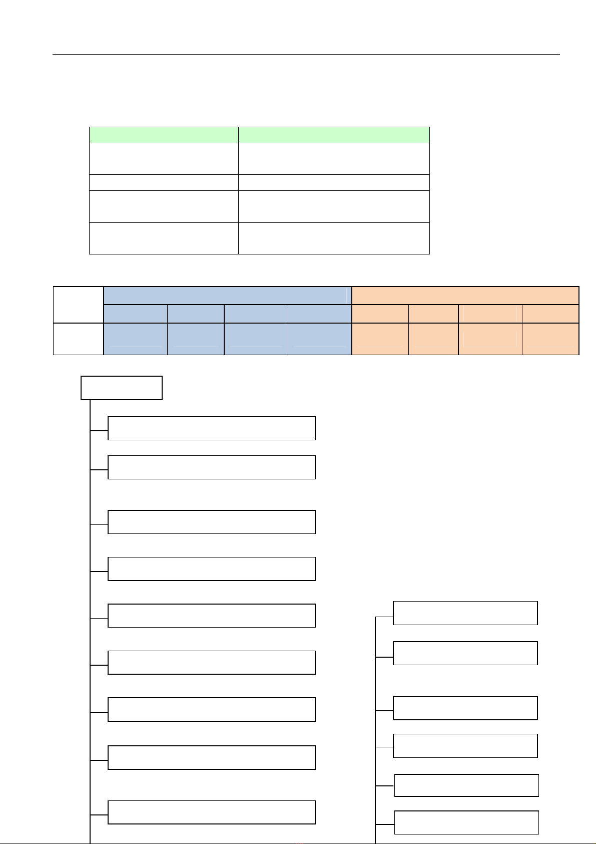
Thermostat t pe
Electronic control
Operation temp ℃ 17-30
Ambient temp ℃ 18~43(cooling); -7~24(heating)
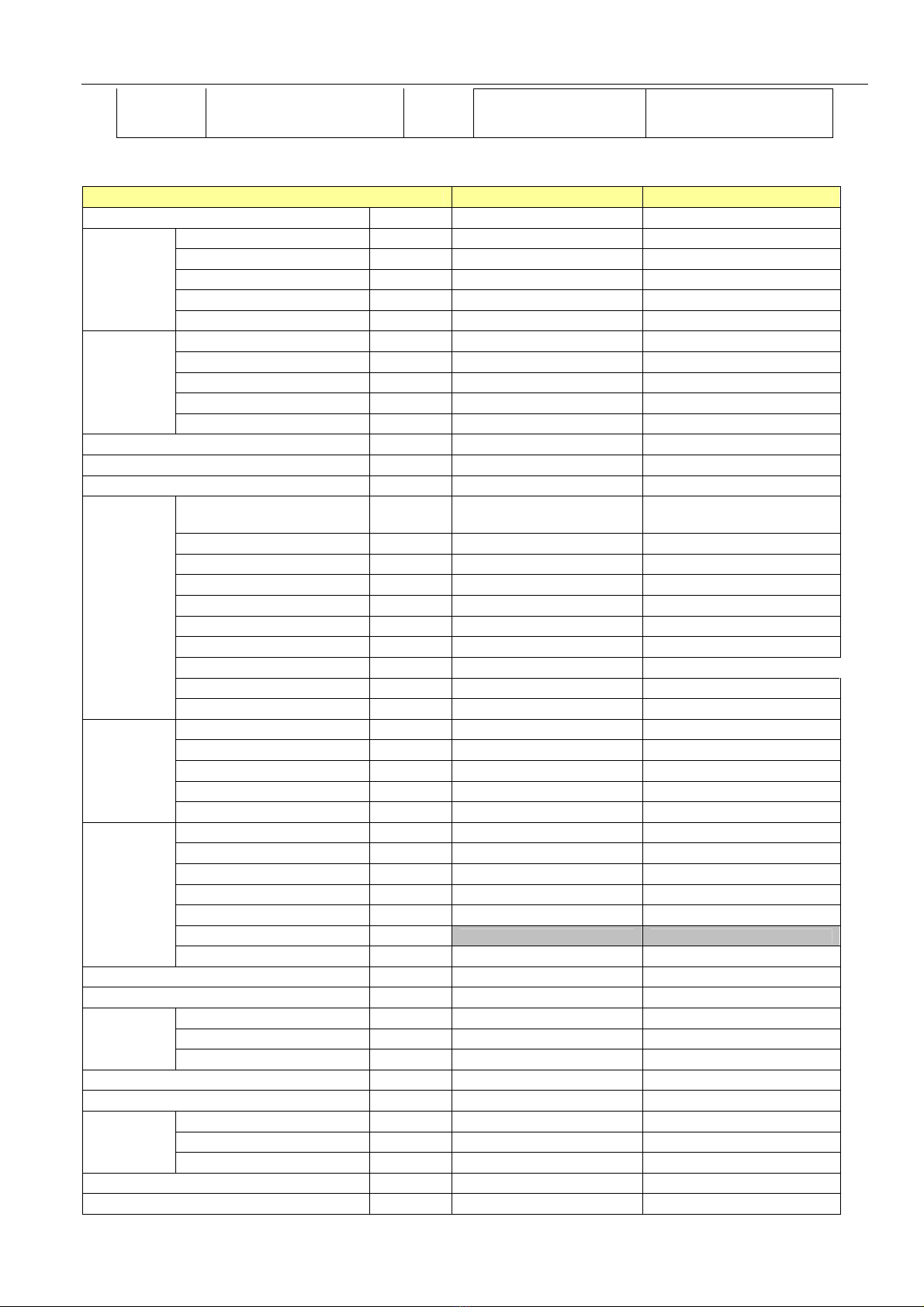
Outdoor Model MSM-27HRN1 MSM-30HRN1
Power suppl Ph-V-Hz 1Ph,220-240V~,50Hz 1Ph,220-240V~,50Hz
Btu/h 27000 30000
W 7913 8792
Input W 2570 2880
Rated current A 13.1 13.7
Cooling
EER w/w
3.03 3.02
Btu/h 30000 34000
W 8792 9965
Input W 2700 3070
Rated current A 13.3 14.2
Heating
EER w/w
3.22 3.22
Max. input power W 3600 3600
Max. current A 16.6 16.6
Starting current A 31.8 31.8
Model
PA200X2CS-4KU1;
PA145X2C-4FT
PA200X2CS-4KU1;
PA145X2C-4FT
T pe
ROTARY ROTARY
Brand
TOSHIBA TOSHIBA
Capacit Btu/h 16791+12014 16791+12014
Input W 1670+1200 1670+1200
Rated current(RLA) A 7.81+5.6 7.81+5.6
Locked rotor Amp(LRA) A 57+57 57+57
Thermal protector
Internal Internal
Capacitor uF 45+35uF/370VAC 45+35uF/370VAC
Compressor
Refrigerant oil ml 750+480 750+480
Model
YDK50-4G1 YDK50-4G1
Brand
Welling Welling
Input W 200 200
Capacitor uF 4uFx2 4uFx2
Outdoor fan
motor
Speed r/min 1150 1150
a.Number of rows
2 2
b.Tube pitch(a)x row pitch(b) mm 25.4x24 25.4x24
c.Fin spacing
mm 1.7 1.7
d.Fin t pe (code)
H drophilic aluminium H drophilic aluminium
e.Tube outside dia.and t pe mm Ф9.53, Innergroove tube Ф9.53, Innergroove tube
f.Coil length x height x width mm 813X812X44 813X812X44
Outdoor coil
g.Number of circuits
3/3 3/3
Outdoor air flow m3/h 3200 3200
Outdoor noise level dB(A) 58 58
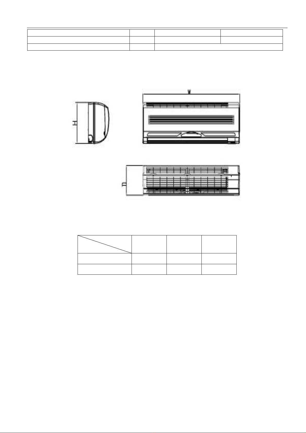
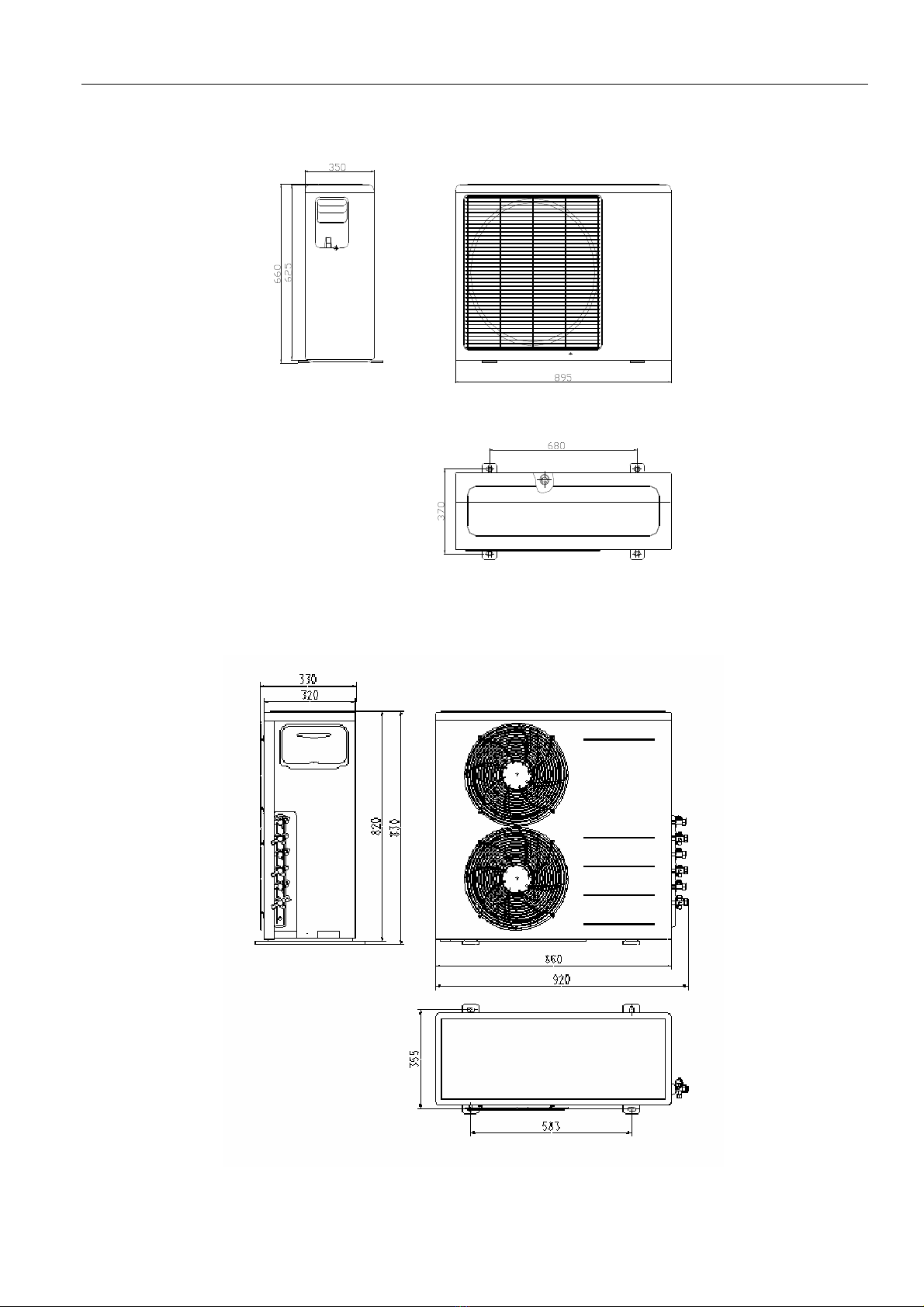
Dimension(W*H*D) mm 860X830X330 860X830X330
Packing (W*H*D) mm 1000X985X425 1000X985X425
Outdoor unit
Net/Gross weight Kg 81/90 81/90
Refrigerant t pe R410A g 1550+1150 1550+1150
Design pressure(Hi/Lo) MPa 4.4/2.0 4.4/2.0
Liquid side/ Gas side mm(inch) Ф6.35/Ф9.53
Ф6.35/Ф12.7
Max. refrigerant pipe length m 15 15
Refrigerant
piping
Max. difference in level m 10 10
Connection wiring
No
Plug t pe
No