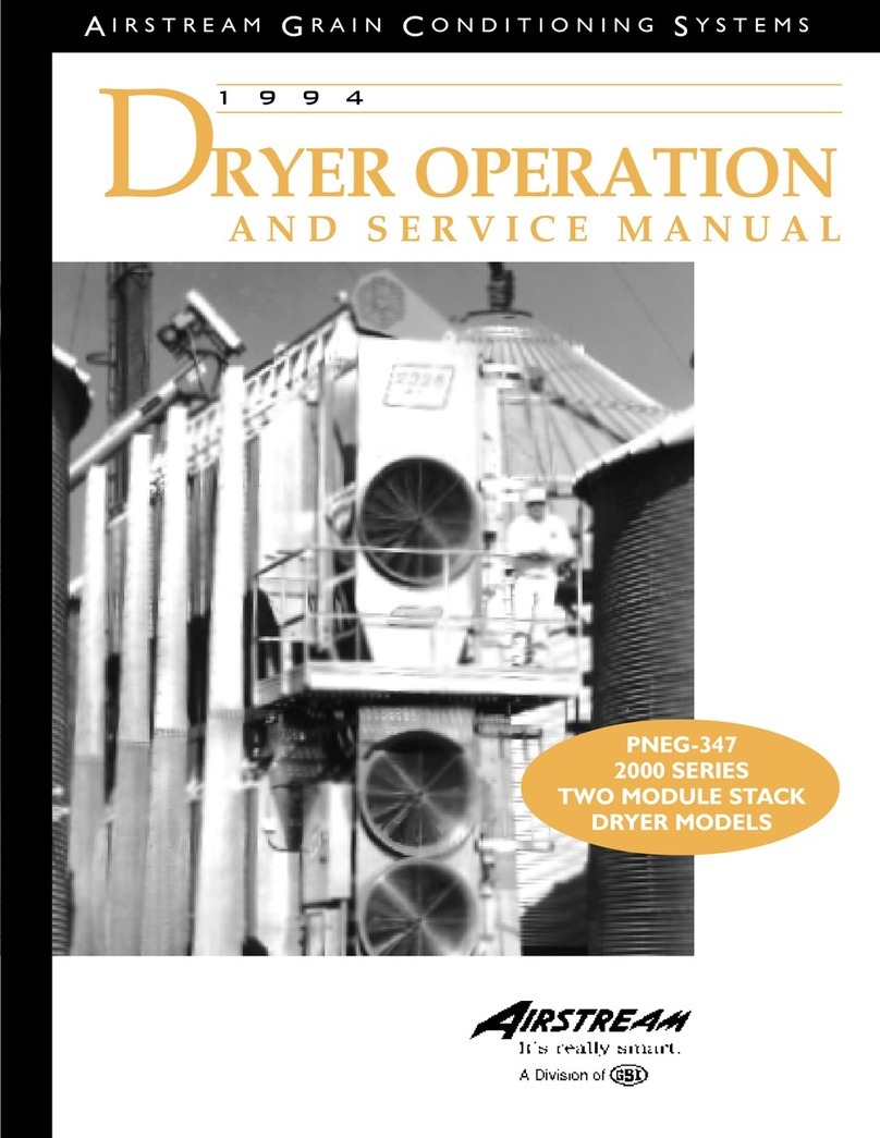
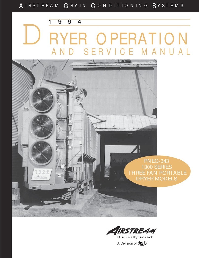
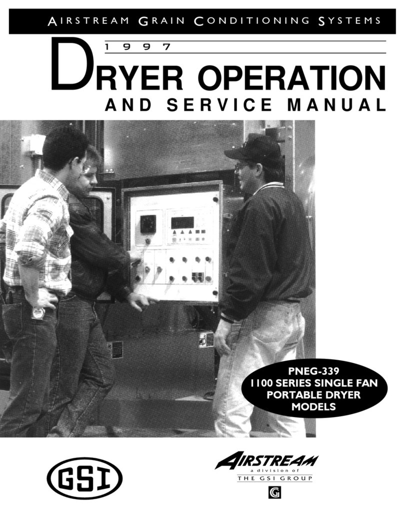
Airstream 1000 Series User manual

1
1 9 9 6
DRYER START UP
Q U I C K R E F E R E N C E G U I D E
AI R S T R E A M GR A I N CO N D I T I O N I N G SY S T E M S
PNEG-523
1000, 2000 & 3000 SERIES
DRYER MODELS

2

3
DRYER START UP REFERENCE GUIDE
TABLE OF CONTENTS
Warranty and Roof Damage Warning...........................................................................4
SafetyFirst...................................................................................................................5
StartUpProcedure...................................................................................................6
FullStartUpCheck..........................................................................................6
FillingTheDryer..............................................................................................6
StartingTheDryer......................................................................................7
AdjustingTheTemperature.............................................................................7
Full Heat-Continuous Flow Operation..........................................................8
1200 Series Continuous Flow Metering Roll Settings...................................9
Dry And Cool-Continuous Flow Operation For Dryers With Two or More Fans..10
1200 Series Continuous Flow Metering Roll Settings.........................................11
Adjusting The Moisture Control..................................................................12
Notes.....................................................................................................................14
QuickStartUpProcedure.......................................................................................15
Electronic Monitoring Control System-Quick Reference................................15
Starting The Drying Process For Full Heat Operation......................................16

4
This manual describes the
start up of Airstream Dryers. Many
different models are available, in-
cluding the 1000, 2000 and 3000
Thank you for choosing an Air-
stream product. It is designed to
give excellent performance and
service for many years.
series models. If the unit is in-
stalled and operated properly, ac-
cording to specification, you can
be assured many years of service.
DRYER START UP REFERENCE GUIDE
consequential damages, nor shall
Airstream's liability ever exceed the
selling price of the product.
This warranty does not cover
products or parts that have been
damaged by negligent use, misuse,
alteration or accident. All products
supplied by outside manufacturers
are warranted separately by the re-
spective manufacturer. This war-
ranty is exclusive and in lieu of all
other warranties, expressed or im-
plied. Airstream reserves the right
to make design or specification
changes at any time, without any
contingent obligation to purchasers
of products already sold.
All instructions shall be con-
strued as recommendations only,
because the actual installation may
vary according to local conditions.
Airstream assumes no liability for
results arising from the use of such
recommendations.
Grain Systems, Inc. assumes
no responsibility for field modifica-
tions or erection defects that create
structural or storage quality prob-
lems. If any field modifications are
necessary that are not specifically
covered by the contents of this
manual, contact Grain Systems, Inc.
for recommendations and approval.
Any unauthorized modification or
erection defect that effects the struc-
tural integrity of the GSI product will
be cause for immediate nullification
of the GSI warranty.
Airstream warrants all products
manufactured by Airstream to be
free of defects in materials and
workmanship under usual and cus-
tomary service. Airstream's only ob-
ligation is to repair or replace prod-
ucts returned on a prepaid basis
within 24 months after retail sale,
and in our opinion, found to be de-
fective by Airstream. If defective,
the product will be repaired or re-
placed without charge, F. O. B. fac-
tory, this constituting and fulfilling
our warranty obligation. Expenses
incurred without written authoriza-
tion from Airstream shall be the sole
responsibility of the bearer. Under
no circumstances will Airstream be
liable for any kind of special or
WARRANTY
Airstream cannot warrant any roof damages due to excessive
vacuum or internal pressure caused by fans or other air mov-
ing systems. Adequate ventilation and/or "make-up air" de-
vices should be provided for all powered air handling systems.
Airstream does not recommend the use of downward flow
systems (suction). Severe roof structural damage can result
from any blockage of air passages. Running of fans during
certain high humidity/cold weather conditions can cause freez-
ing over of air exhaust or intake ports.
ROOF DAMAGE WARNING

5
SAFETY FIRST
SAFETY ALERT DECALS
Grain Systems, Inc.'s principal con-
cern is your safety and the safety of
others associated with grain han-
dling equipment. This manual is writ-
ten to help you understand safe op-
erating procedures, and some of the
problems that may be encountered
by the operator or other personnel.
As owner and/or operator, it is
your responsibility to know what re-
quirements, hazards and precau-
tions exist, and to inform all person-
nel associated with the equipment,
or who are in the dryer area. Avoid
any alterations to the equipment.
Such alterations may produce a very
dangerous situation, where serious
injury or death may occur.
Safety decals should be read and
understood by all people in the grain
handling area. The right decal
should be present on the inside door
cover of the two ring door, 24" port-
hole door cover and the roof
manway cover. If a decal has been
damaged or is missing contact:
Grain Systems, Inc.
1004 E. Illinois St.
Assumption, IL 62510
217-226-4421
A free replacement will be sent to you.
WARNING! BE ALERT!
Personnel operating or working around
electric fans should read this manual.
This manual must be delivered with the
equipment to its owner. Failure to read
this manual and its safety instructions is
a misuse of the equipment.
The symbol shown is used to call
your attention to instructions con-
cerning your personal safety. Watch
for this symbol; it points out impor-
tant safety precautions. It means
"ATTENTION", "WARNING", "CAU-
TION", and "DANGER". Read the
message and be cautious to the
possibility of personal injury or
death.
SAFETY ALERT SYMBOL
Grain Systems, Inc. recom-
mends that you contact your local
power company, and have a repre-
sentative survey your installation so
your wiring will be compatible with
their system and you will have ad-
equate power supplied to your unit.

6
START UP PROCEDURE
Standard electrical safety practices
and codes should be used when
working with a dryer. Refer to the
National Electric Code Standard
Handbook by the National Fire Pro-
tection Association.
A qualified elec-
trician should make all wiring instal-
lations.
FULL START UP CHECK
ALWAYS DISCONNECT
AND LOCK OUT POWER
BEFORE WORKING ON OR
AROUND DRYER
This start up procedure assumes the following:
1. That you have read and understand the DRYER OPERATION AND
SERVICE MANUAL.
2. That you have taken special note of all SAFETY PRECAUTIONS.
3. That all safety shields are in place.
4. That all meter roll access doors have been opened and all foreign ob-
jects have been removed.
5. That you have done a pre-start up check out.
6. That all motors have been checked for proper rotation.
7. That all heaters have been test fired.
8. That the fuel has been turned on at the tank.
9. That the electric power has been turned on.
10. That the main disconnect switch on the dryer is on.
11. That you have wet grain in the wet holding bin.
12. That you know the incoming grain moisture.
13. That you have the dry grain take away equipment in place.
14. That you have the grain going to the proper bin.
15. That all switches have been set to the off position.
16. That the load mercury switch box is installed with the side stamped up,
in the up position.
FILLING THE DRYER
1. Turn the green CONTROL POWER knob to ON. It should light up, go
through 4 screens and end with the time and date.
2. Turn the DRYING MODE switch to CONTINUOUS FLOW.
3. Push the RESET on the computer key pad to activate the computer.
4. Make sure the UNLOAD switch is in the OFF position.
5. Push the DRYER POWER start switch, it should light up.
6. Turn the LOAD AUGER switch to the MANUAL position to fill the dryer.
The load auger should start and run until the dryer is full, then shut off
automatically. (If the switch is set to the AUTO position the dryer will
shut down each time the out of grain timer times out, and will have to be
restarted.)
7. When the dryer has filled, turn the LOAD AUGER switch to the AUTO
position.

7
START UP PROCEDURE
STARTING THE DRYER
This start up procedure is for a cold start on wet grain for continuous flow
operation.
1. Set the MAXON or FAST ACTION HAND VALVE on the incoming fuel
line to the ON position.
2. Make sure the MOISTURE CONTROL switch is in the OFF position.
3. Turn the FAN switch (or switches if a multi-fan dryer) to the ON posi-
tion. The light in the switch should light when the fan comes up to
about half speed.
4. Adjust the AIR PRESSURE SWITCH if necessary.
5. Turn the HEATER switch (or switches if a multi-fan dryer) to the ON
position. The heater will purge for about 10 seconds then ignite. The
light in the heater switch will come on during ignition and will stay on if
the heater ignites. If the heater does not ignite, the light will go out after
trial for ignition and the dryer will shut down, indicating that it did not
light. If this happens check gas supply, and all valves in the fuel line to
make sure they are ON.
ADJUSTING THE TEMPERATURE
1. Set the HI-LOW FIRE PLENUM THERMOSTAT on the left side of the
dryer to the drying temperature that you want to run (180 deg. to 200
deg.). On multiple fan dryers set the heat chambers 30 to 60 degrees
apart. Hottest at the top, most cool at the bottom.
2. On LP gas models adjust the PRESSURE REGULATOR (high fire) on
the burner fuel line, so that burner will reach the thermostat setting and
switch to (low fire) (pressures may be required up to 25 lbs.). Natural
gas does not have a regulator, but uses a LARGE BALL VALVE close
to the vertical supply line for adjustment (pressures may be required up
to 18 lbs.).
On LP gas models adjust the small RED HANDLED BALL VALVE
(low fire) so that the burner maintains flame then switches back to (high
fire). Natural gas has a BALL VALVE close to the burner control box,
for low fire adjustment.
3. Adjust the burner pressure so that the burners CYCLES 4 times per
minute (approx. 10 sec. on HIGH--approx. 5 sec. on LOW). When on
HIGH FIRE increasing the pressure with the pressure regulator DE-
CREASES the time spent on high fire. When on LOW FIRE increasing
the low fire pressure with the RED BALL VALVE INCREASES the time
spent on low fire.
4. On LP gas models adjust the VAPORIZER so the fuel pipes going to
the burner from the regulator are warm to the touch (not hot and cold).
How much gas pressure do I
use? See step number two in
the
Adjusting The Temperature
section.
How often should my burner
cycle? See step number three
in the
Adjusting The Temperature
section.

8
START UP PROCEDURE
1. Look in your operators manual in the DRYER START UP section (CON-
TINUOUS FLOW METER ROLL SETTINGS-FULL HEAT). You will
see the settings for (Initial Moisture) (Moisture Removed) (Approx. Dry
Time) (1 Speed) (2 Speed Low) (2 Speed High) pick the line that has
your initial starting moisture. These are the settings we will be referring
to during this start up procedure.
2. Make sure the UNLOAD switch is OFF.
3. Make sure the MOISTURE CONTROL switch is OFF.
4. Run the fan(s) and heater(s) for about 10% longer than the (APPROX.
DRYING TIME) required for the moisture you are trying to dry.
5. Example: 10% removal would be about 54 minutes, 15% removal would
be about 76 minutes and 20% removal would be about 100 minutes.
Add 10 minutes to insure that the grain is dry.
6. After the time in step 4 turn the UNLOAD to 1 SPEED and set the
METER ROLL SPEED, (HIGH SPEED) pot. to the setting for 1 SPEED
operation. Grain should begin to run at this time. Run time for this is
about 10% longer than the (APPROX. DRYING TIME) required for the
moisture you are trying to dry, as shown in the example #5 above. This
allows the moisture in the dryer to reach an even gradient top to bottom
without having any highs or lows in it. It will however, over dry some of
the corn a little.
7. Increase the drying temperature to 190 deg. for single fans or for mul-
tiple fan dryers set the heat chambers 30 to 60 degrees apart. Hottest
at the top, most cool at the bottom.
8. DO NOT TRY TO ADJUST THE DRYER FOR MOISTURE DURING
THIS PROCESS OR YOU WILL ESTABLISH HIGH AND LOW
SWINGS IN THE MOISTURE CONTROL. IT WILL TAKE SEVERAL
HOURS TO WORK ITSELF OUT.
9. After the run time in step 6 you are ready to set up the moisture control.
Now turn the MOISTURE CONTROL to the ON position. Set the tem-
perature to about 100 deg.
10. Turn the UNLOAD to 2 SPEED. Set the METER ROLL SPEED, LOW
SPEED and HIGH SPEED pots. to the settings listed for them. Let the
dryer run on these settings as shown in the example #5 before trying to
How often do I make speed
adjustment? See step number
ten in the
Full Heat-Continuous
Flow Operation
section.
The vaporizer can be adjusted two ways. First, by loosening the bolt in
the hinging mechanism and swinging it to a hotter or cooler position.
Second, by loosening the two bolts in the hinge pipe and sliding the
vaporizer in or out to a cooler or hotter position. Either one or both
methods may have to be used to get the vaporizer to the proper tem-
perature. Natural gas does not use a vaporizer.
FULL HEAT-CONTINUOUS FLOW OPERATION

9
START UP PROCEDURE
adjust moisture or meter roll settings. These settings will not have your
grain moisture adjusted exactly where you want it, but will be a good
place to start initially. A little different moisture at the bottom of the
storage bin is not usually a problem as long as you have full floor aera-
tion.
11. After the run time in step 10 you are ready to adjust the moisture con-
trol, and the meter roll speeds if required. Each time you make an
adjustment to the moisture control it will take about the time shown in
example #5 to see the results of this adjustment.
1100 & 1200 SERIES CONTINUOUS FLOW METERING ROLL SETTINGS
Initial
Moisture
17%
18%
19%
20%
21%
22%
23%
24%
25%
26%
27%
28%
29%
30%
31%
32%
33%
34%
35%
2 Speed
High
875
775
675
575
476
385
317
270
241
213
196
185
172
161
150
140
132
123
116
2 Speed
Low
317
270
241
213
196
185
172
161
150
140
132
123
116
110
104
100
096
087
082
1 Speed
625
476
385
317
270
241
213
196
185
172
161
150
140
132
123
116
110
104
100
Approx.
Dry Time
16 min.
21 min.
26 min
31.5 min.
37 min.
41.5 min.
47 min.
51 min.
54 min.
58 min.
62 min.
66.5 min.
71.5 min.
76 min.
81 min.
86 min.
91 min.
96 min.
100 min.
Moisture
Removed
2 pts.
3 pts.
4 pts.
5 pts.
6 pts.
7 pts.
8 pts.
9 pts.
10 pts.
11 pts.
12 pts.
13 pts.
14 pts.
15 pts.
16 pts.
17 pts.
18 pts.
19 pts.
20 pts.
Full Heat
These are approximate starting points.

10
START UP PROCEDURE
1. Look in your operators manual in the DRYER START UP section (CON-
TINUOUS FLOW METER ROLL SETTINGS-DRY & COOL). You will
see the settings for (Initial Moisture) (Moisture Removed) (Approx. Dry
Time) (1 Speed) (2 Speed Low) (2 Speed High) pick the line that has
your initial starting moisture. These are the settings we will be referring
to during this start up procedure.
2. Make sure the UNLOAD switch is OFF.
3. Make sure the MOISTURE CONTROL switch is OFF.
4. Run the bottom fan(s) and heater(s) (to be used for cooling later) for
about 20 minutes. This will start the bottom drying so we can cool it
before we begin to discharge grain.
5. Take the remaining number of burners to be started, divide that into the
total drying time required, working up, start each burner that many min-
utes apart. Run them about 10% longer than the (APPROX. DRYING
TIME) total required for the moisture you are trying to dry.
6. Example: 10% removal would be about 60 minutes, 15% removal would
be about 85 minutes, and 20% removal would be about 110 minutes.
Add 10 minutes to insure that the grain is dry.
7. After the required drying time turn the bottom heater (OFF) cool this
section for about 20 minutes. Set the upper plenum thermostats to the
decreed temperature (190°-230°F)
8. Turn the UNLOAD to 1 SPEED and set the METER ROLL SPEED
(HIGH SPEED) pot. to the setting for 1 SPEED operation. Run time for
this is about 10% longer than the (APPROX. DRYING TIME) required
for the moisture you are trying to dry, as shown in the example #6.
above. This allows the moisture in the dryer to reach an even gradient
top to bottom without having any highs or lows in it. It will however,
over dry some of the corn a little.
9. DO NOT TRY TO ADJUST THE DRYER FOR MOISTURE DURING
THIS PROCESS OR YOU WILL ESTABLISH HIGH AND LOW
SWINGS IN THE MOISTURE CONTROL. IT WILL TAKE SEVERAL
HOURS TO WORK ITSELF OUT.
10. After the run time in step 8 you are ready to set up the moisture control.
Now turn the MOISTURE CONTROL to the ON position. Set the tem-
perature to about 130 deg.
11. Turn the UNLOAD to 2 SPEED. Set the METERING ROLL SPEED,
LOW SPEED and HIGH SPEED pots. to the settings listed for them.
Let the dryer run on these settings as shown in the example #6 before
trying to adjust moisture or meter roll settings. These settings will not
DRY AND COOL-
CONTINUOUS FLOW OPERATION
FOR DRYERS WITH TWO OR MORE FANS
What temperature should I
dry at? See step number seven
in the
Dry and Cool-Continuous
Flow Operation for dryers with
Two or More Fans
section.

11
have your grain moisture adjusted to exactly where you want it, but it
will be a good starting place to adjust from. A little different moisture at
the bottom of the storage bin is not usually a problem as long as you
have full floor aeration.
12. After the run time in step 11, you are ready to adjust the moisture con-
trol and the meter roll speeds if required. Each time you make an
adjustment to the moisture control it will take about the time shown in
example #6 to see the results of this adjustment.
START UP PROCEDURE
1100 & 1200 SERIES CONTINUOUS FLOW METERING ROLL SETTINGS
Initial
Moisture
17%
18%
19%
20%
21%
22%
23%
24%
25%
26%
27%
28%
29%
30%
31%
32%
33%
34%
35%
2 Speed
High
650
550
450
363
272
218
187
163
145
131
119
109
101
093
087
082
077
073
069
2 Speed
Low
187
163
145
131
119
109
101
093
087
082
077
073
069
065
061
057
053
049
045
1 Speed
363
272
218
187
163
145
131
119
109
101
093
087
082
077
073
069
065
062
059
Approx.
Dry Time
18 min.
24 min.
30 min
35 min.
40 min.
45 min.
50 min.
55 min.
60 min.
65 min.
70 min.
75 min.
80 min.
85 min.
90 min.
95 min.
100 min.
105 min.
110 min.
Moisture
Removed
2 pts.
3 pts.
4 pts.
5 pts.
6 pts.
7 pts.
8 pts.
9 pts.
10 pts.
11 pts.
12 pts.
13 pts.
14 pts.
15 pts.
16 pts.
17 pts.
18 pts.
19 pts.
20 pts.
Dry & Cool
These are approximate starting points.

12
START UP PROCEDURE
How do I set my moisture
control? See step number one
in the
Adjusting The Moisture
Control
section.
ADJUSTING THE MOISTURE CONTROL
1. Each 5 deg. on the MOISTURE CONTROL will change the output mois-
ture by about 1%. Example: you have 100 deg. set, you are getting
16% corn out, you want 17% corn out, so you would reduce the MOIS-
TURE CONTROL temperature by 5 deg. to 95 deg. and this should
change the moisture out to about 17%. If you wanted the corn to come
out dryer, you would raise the temperature on the MOISTURE CONTROL.
2. There are 4 sensors that are averaged together for sensing MOIS-
TURE CONTROL temperature, 1 on each side of the dryer in the front,
and 1 on each side of the dryer in the back. They are located about
1/3 of the way up the grain column from the bottom, and in from the
side about 4 inches.
3. The small lights behind the temperatures on the MOISTURE CON-
TROL indicate the temperature of the grain at this sample point.
4. The 2 lights in the center are green, the lights to the right or to the left of
these are red.
5. When the grain temperature has the dryer cycling HIGH and LOW speed
on the green lights the moisture setting is being maintained correctly.
6. Set the METER ROLL SPEED in relation to the small red lights behind
the temperatures on the MOISTURE CONTROL.
7. RED lights to the left indicate that the grain at the sample point is too
cool or wetter than desired. With this condition turn the (LOW SPEED)
left pot. to a lower number. This will slow down the meter rolls and dry
the grain longer, warming it up.
8. RED lights to the right indicate that the grain at the sample point is too
hot or dryer than desired. With this condition turn the (HIGH SPEED)
right pot. to a higher number. This will speed up the meter rolls and
remove the grain quicker, cooling it down.
9. If the MOISTURE CONTROL switches to LOW and only stays on low
for a minute or two and switches back to HIGH, speed up the (LOW
SPEED) left pot. It is set too slow.
10. If the MOISTURE CONTROL switches to HIGH and only stays on low
for a minute or two and switches back to LOW, slow down the (HIGH
SPEED) right pot. It is set too fast.
11. The MOISTURE CONTROL should stay on HIGH about 50% of the
time and on LOW about 50%, give or take 25%. There is a broad range
that will work. It should be switching low to high and back to maintain
the desired moisture. A control that does not switch, will not maintain
an evenly dried grain moisture, when the incoming wet grain moisture
is varying.
12. When adjusting the meter roll speeds it is better not to change the
speed more than 20 points at a time.

13
START UP PROCEDURE

14
______________________________________________________________________________________________________
_______________________________________________________________________________________________________
______________________________________________________________________________________________________
__________________________________________________________________________________________________________
___________________________________________________________________________________________________________
__________________________________________________________________________________________________________
________________________________________________________________________________________________________
__________________________________________________________________________________________________________
_________________________________________________________________________________________________________
_______________________________________________________________________________________________________
_________________________________________________________________________________________________________
_______________________________________________________________________________________________________
__________________________________________________________________________________________________
___________________________________________________________________________________________________
_____________________________________________________________________________________________________
____________________________________________________________________________________________________
________________________________________________________________________________________________________
_______________________________________________________________________________________________________
________________________________________________________________________________________________________
_________________________________________________________________________________________________________
________________________________________________________________________________________________________
______________________________________________________________________________________________________
________________________________________________________________________________________________________
____________________________________________________________________________________________________
_______________________________________________________________________________________________________
______________________________________________________________________________________________________
___________________________________________________________________________________________________________
NOTES

15
QUICK START UP PROCEDURE
Please read the manual for
your dryer model, before using
the quick reference. IMPORTANT! To activate the controller after turning on the control power,
press the RESET button.
Setting the DRY, COOL, UNLOAD & OUT OF GRAIN timers:
• Press the DRY, COOL, UNLOAD or OUT OF GRAIN button.
• Press the MODIFY button.
• Press the INCREASE or DECREASE button to get desired setting.
• Press the ENTER button when desired setting is reached.
Setting the LOAD & UNLOAD DELAYS:
• Press the LOAD or UNLOAD button.
• Press the MODIFY button.
• Press the INCREASE or DECREASE button to get desired setting.
• Press the ENTER button when desired setting is reached.
Pressing the INCREASE and DECREASE buttons simultaneously will ac-
cess the following programming features:
• SAFETY CIRCUIT SHUTDOWN LOG
• DRYER MODEL NUMBER
• FAN DELAY
• BPH FACTOR
• METERING ROLL MONITOR DISABLING FEATURE
• AIR SWITCH DISABLING FEATURE
These features are accessed sequentially as listed above. Press the IN-
CREASE or DECREASE buttons to change a setting. Press the ENTER
button to move from feature to feature.
Pressing and holding the RESET button for five (5) seconds will access the
following programming features:
• CALENDAR YEAR SETTING
• CALENDAR MONTH SETTING
• CALENDAR DAY SETTING
• CLOCK HOUR SETTING
• CLOCK MINUTE SETTING
• BUSHEL COUNTER RESET
• BATCH COUNTER RESET
These features are accessed sequentially as listed above. Press the IN-
CREASE or DECREASE buttons to change a setting. Press the ENTER
button to move from feature to feature.
Changing the Marquee on the LCD display:
• Press and hold the MODIFY button while turning on the control power.
• To change a character press the INCREASE or DECREASE button.
• To move the cursor to right press the UNLOAD button.
• To move the cursor to the left press the DRY button.
• To delete a character press the COOL button.
• Press ENTER when the desired marquee is displayed.
ELECTRONIC MONITORING
CONTROL SYSTEM-QUICK REFERENCE

16
QUICK START UP PROCEDURE
1. Control Power--ON
2. Drying Mode--CONTINUOUS FLOW
3. Push the computer RESET
4. Push dryer power START SWITCH
5. Unload--OFF
6. Load Auger--MANUAL, after dryer is full switch to AUTO
7. Maxon or Fast Action Hand Valve--ON
8. Moisture Control--OFF
9. Fan Switch--ON
10. Heater--ON
11. Plenum Thermostat--180 deg. to 200 deg. to start dryer
12. Adjust gas pressure regulators
13. Adjust vaporizers
Read and understand the full
start up procedure before us-
ing this quick abbreviated
guide.
STARTING THE DRYING PROCESS FOR
FULL HEAT OPERATION
1. Unload--OFF
2. Moisture Control--OFF
3. Run fan and heater--designated time plus--10% to 15%
4. After 1st hour--Unload to 1 SPEED
5. Increase drying temperature--190 deg. to 230 deg. as desired
6. Readjust vaporizers if required
7. Meter roll speed (HIGH SPEED)--set as chart specifies
8. After 2nd hour--Moisture Control--ON--set at about 100 deg.
9. Unload--2 SPEED
10. Meter roll--LOW SPEED and HIGH SPEED
11. After 3rd hour--adjust moisture as required
12. Do not make corrections to the moisture more than once per hour
Check settings listed in main
manual.
1004 E. Illinois St.
Assumption, IL 62510
phone 217-226-4421
fax 217-226-4498
This manual suits for next models
2
Table of contents
Other Airstream Dryer manuals
Popular Dryer manuals by other brands

Bosch
Bosch WTM8326SZA Installation and operating instructions

ADC
ADC ML-22 Installation & operator's manual

Whirlpool
Whirlpool LER4624DQ0 parts list

Whirlpool
Whirlpool WED9270XL2 parts list

Bosch
Bosch WTG86402GB Installation and operating instructions

Kenmore
Kenmore 8041 - 5.8 cu. Ft. Capacity Electric Dryer installation instructions