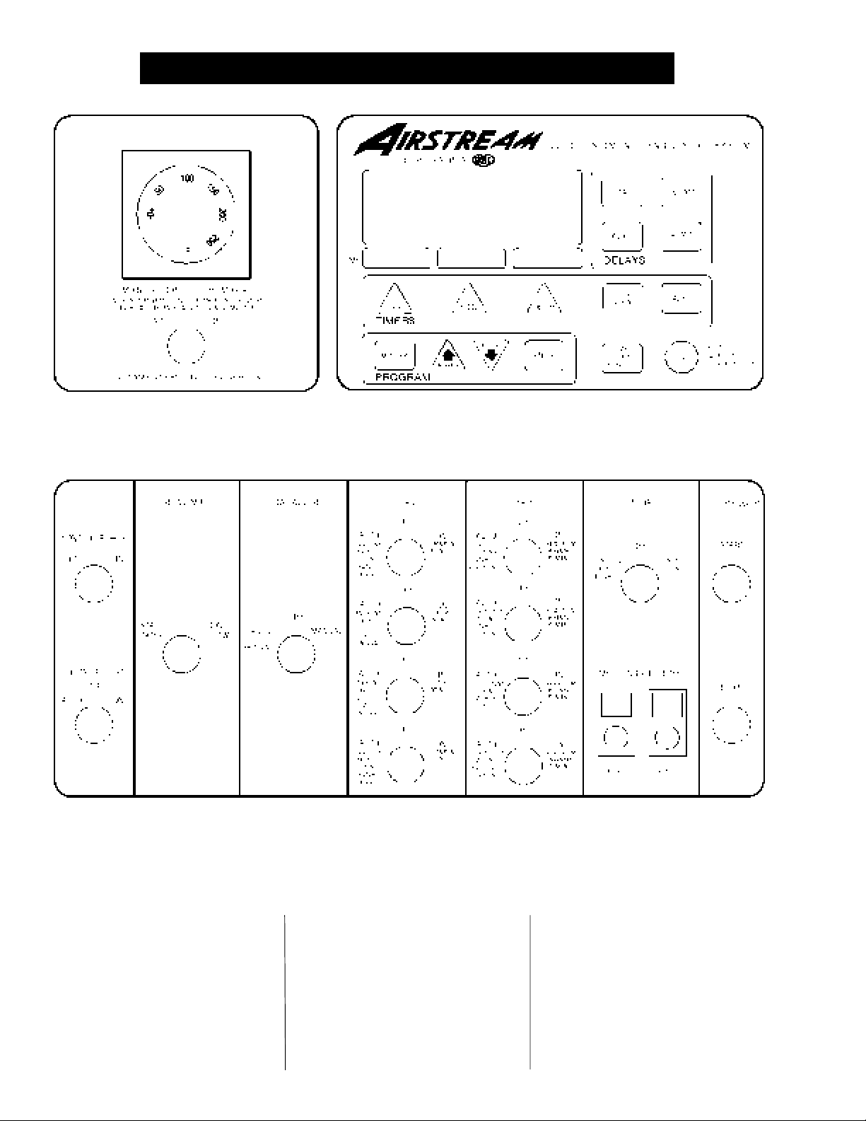
manuals.online logo
Brands
  1. Home
  2. •
  3. Brands
  4. •
  5. Airstream
  6. •
  7. Dryer
  8. •
  9. Airstream 2000 Series Operation manual

Airstream 2000 Series Operation manual

This manual suits for next models

1

Other Airstream Dryer manuals

Airstream 1100 SERIES Operation manual

Airstream

Airstream 1100 SERIES Operation manual

Airstream 1000 Series User manual

Airstream

Airstream 1000 Series User manual

Airstream PNEG-343 Operation manual

Airstream

Airstream PNEG-343 Operation manual

Popular Dryer manuals by other brands

Whirlpool WED9270XL2 parts list

Whirlpool

Whirlpool WED9270XL2 parts list

Kleenmaid KED2000 Repair instructions

Kleenmaid

Kleenmaid KED2000 Repair instructions

SPI Supplies SPI-DRY Operation manual

SPI Supplies

SPI Supplies SPI-DRY Operation manual

Amana NGD5800DW Use & care guide

Amana

Amana NGD5800DW Use & care guide

Bosch WTG86402GB Installation and operating instructions

Bosch

Bosch WTG86402GB Installation and operating instructions

Maytag MED4200BW0 installation instructions

Maytag

Maytag MED4200BW0 installation instructions

ffuuss eos user manual

ffuuss

ffuuss eos user manual

KitchenAid 53-3498 installation instructions

KitchenAid

KitchenAid 53-3498 installation instructions

Schulthess Spirit topLine TW 8340 operating instructions

Schulthess

Schulthess Spirit topLine TW 8340 operating instructions

Whirlpool LGR4624BW0 parts list

Whirlpool

Whirlpool LGR4624BW0 parts list

World Dryer AirMax D M5-972A manual

World Dryer

World Dryer AirMax D M5-972A manual

Alliance Laundry Systems ADEE9BSS user guide

Alliance Laundry Systems

Alliance Laundry Systems ADEE9BSS user guide

Miele PDR 910 EL Operating and installation instructions

Miele

Miele PDR 910 EL Operating and installation instructions

Amana NGD5800TQ0 parts list

Amana

Amana NGD5800TQ0 parts list

Bosch WTA79200GB Installation and operating instructions

Bosch

Bosch WTA79200GB Installation and operating instructions

AEG TR838P4OB user manual

AEG

AEG TR838P4OB user manual

Asko T760 user guide

Asko

Asko T760 user guide

Electrolux EW2H328R2 user manual

Electrolux

Electrolux EW2H328R2 user manual

manuals.online logo
manuals.online logoBrands
  • About & Mission
  • Contact us
  • Privacy Policy
  • Terms and Conditions

Copyright 2025 Manuals.Online. All Rights Reserved.

1
AI R S T R E A M GR A I N CO N D I T I O N I N G SY S T E M S
A N D S E R V I C E M A N U A L
DRYER OPERATION
1 9 9 4
PNEG-347
2000 SERIES
TWO MODULE STACK
DRYER MODELS
2
3
Warranty.......................................................................................................................4
Safety First...................................................................................................................5
Safety Alert Decals.......................................................................................................6
Safety Precautions.......................................................................................................7
Dryer Control Panel Featuring The Electronic Monitoring Control System.......................8
Safety Circuit Shutdown Messages......................................................................12
Dryer Pre Start Checks...............................................................................................14
Pre Season Inspection..........................................................................................14
Dryer Start Up & Operation..............................................................................................18
Continuous Flow And Continuous Batch Start Up Procedure..............................18
2200 Series Continuous Flow Metering Roll Settings-Full Heat...............................19
2200 Series Continuous Flow Metering Roll Settings-Dry & Cool.............................20
2300 & 2400 Series Continuous Flow Metering Roll Settings-Full Heat..............21
2300 & 2400 Series Continuous Flow Metering Roll Settings-Dry & Cool...........22
Fan & Heater Switch Settings...............................................................................24
2000 Series Staged Auto Batch Timer Settings....................................................26
2000 Series Dryer Service Guide.....................................................................................27
Seasonal Inspection And Service.........................................................................28
Suggested Lubricants..........................................................................................29
Fan Propellor Removal And Installation...............................................................30
Fan Motor Removal And Installation....................................................................31
Heater Parts Removal And Installation................................................................32
Metering Roll Servicing........................................................................................33
How To Determine A Metering Roll Problem........................................................34
2200 Series Wiring Diagrams.......................................................................................35
2300 Series Wiring Diagrams.....................................................................................46
2400 Series Wiring Diagrams.....................................................................................57
Trouble Analysis Procedure...................................................................................68
Quick Reference Guide........................................................................................73
Notes...................................................................................................................74
2000 SERIES DRYER OPERATION AND SERVICE
TABLE OF CONTENTS
4
2000 SERIES DRYER OPERATION AND SERVICE
This manual describes the
operation and service for all stan-
dard production 2000 series two
module grain dryers. These
models are available for liquid
Thank you for choosing an Air-
stream Grain Dryer. This dryer is
one of the finest ever built. It is
designed to give excellent perfor-
mance and service for many years.
propane or natural gas fuel sup-
ply, with either single phase 230
volt, or three phase 220 or 440
volt electrical power.
WARRANTY
Grain Systems, Inc. warrants its
products to be free of defects in ma-
terial and workmanship. The only
obligation of the manufacturer is to
repair or replace components which
have been submitted and found to
be defective within 24 months after
installation. If so found to be defec-
tive, the components will be repaired
or replaced without charge, this con-
stituting and entirely fulfilling the
warranty obligation. Grain Systems,
Inc. assumes no liability for ex-
penses incurred without written au-
thorizations; in no event shall liabil-
ity include special or consequential
damages, or exceed the selling price
of the product.
This warranty does not cover
products or parts which have been
damaged by negligent use, misuse,
alteration or accident. Electric mo-
tors, tires, and other components
supplied by outside manufacturers
have separate warranties, from
those suppliers. This warranty is ex-
clusive and in lieu of all other war-
ranties, expressed or implied. Grain
Systems, Inc. reserves the right to
make design or specification
changes at any time, without any
contingent obligations to purchasers
of products already sold.
All instructions shall be con-
strued as recommendation only.
Because of the many variable con-
ditions in actual installation, Grain
Systems, Inc. assumes no liability
for results arising from the use of
such recommendations. Any alter-
ation in design or operation of any
Grain Systems, Inc. product must be
submitted and approved in writing by
Grain Systems, Inc. before the al-
teration is made.
Airstream Service Technician checks the wiring on a dryer control box.
5
SAFETY FIRST
SAFETY ALERT DECALS
Grain Systems, Inc.'s principle con-
cern is your safety and the safety of
others associated with grain han-
dling equipment. This manual was
written with that thought in mind. We
want to keep you as a customer by
helping you understand safe
operating proceedures, and some of
the problems that may be encoun-
tered by the dryer operator or other
personnel.
As owner and/or operator, it is
your responsibility to know what re-
quirements, hazards and precau-
tions exist, and to inform all person-
nel associated with the equipment
or who are in the dryer area. Avoid
any alterations to the equipment.
Such alterations may produce a very
dangerous situation, where serious
injury or death may occur.
SAFETY ALERT SYMBOL
WARNING! BE ALERT!
Personnel operating or working around
a dryer should read this manual. This
manual must be delivered with equip-
ment to its owner. Failure to read this
manual and its safety instructions is a
misuse of the equipment.
The symbol shown below is used to
call your attention to instructions
concerning your personal safety.
Watch for this symbol; it points out
important safety precautions. It
means "ATTENTION", "WARNING",
"CAUTION", and "DANGER". Read
the message that follows and be
cautious to the possibility of per-
sonal injury or death.
Safety decals should be read and
understood by all people in and
around the dryer area. If the follow-
ing safety decals are not displayed
on your dryer, or if they are dam-
aged, contact Grain Systems, Inc.
for replacement.
A CAREFUL OPERATOR
IS THE BEST INSURANCE
AGAINST AN ACCIDENT
Grain Systems, Inc. recommends
you contact your local power com-
pany and have a representative sur-
vey your dryer installation, so your wir-
ing will be compatible with their sys-
tem and you will have adequate power
supplied to your unit.
6
Three decals displayed on all Airstream Dryers. Belt drives, chain driven meter rolls
and combustible fuels must be treated with caution.
SAFETY ALERT DECALS
7
1. Read and understand the operating manual before trying to operate the
dryer.
2. Never operate the dryer while the guards are removed.
3. Power supply should be OFF for service of electrical components.
Use CAUTION in checking voltage or other procedures requiring power
to be ON.
4. Check for gas leaks at all gas pipe connections. If any leaks are
detected, do not operate dryer. Shut down and repair before fur-
ther operation.
5. Never attempt to operate the dryer by jumping or otherwise bypassing
any safety devices on the unit.
6. Set pressure regulator to avoid excessive gas pressure applied to burner
during ignition and
when burner is in operation. See chart for operat-
ing procedures. Do not exceed maxi
mum recommended drying tem-
perature.
7. Keep the dryer clean. Do not allow fine material to accumulate in
the plenum chamber.
8.
Keep auger drive belts tight
enough to prevent slippage.
9. Use CAUTION in working around high speed fans, gas burners, augers
and auxiliary conveyors which START AUTOMATICALLY.
10. Do not operate in any area where combustible material will be drawn into
the fan.
11. Before attempting to remove and reinstall any propeller, make certain to
read the recommended procedure listed within the servicing section of
the manual.
12. Be certain that capacities of auxiliary conveyors are matched to dryer
auger capacities.
13. Clean grain is easier to dry. Fine material increases resistance to airflow
and requires removal of extra moisture.
SAFETY PRECAUTIONS
USE CAUTION
IN THE OPERATION
OF THIS EQUIPMENT
The design and manufacture of this
dryer is directed toward operator
safety. However, the very nature of
a grain dryer having a gas burner,
high voltage electrical equipment
and high speed rotating parts, does
present a hazard to personnel,
which can not be completely safe-
guarded against, without interfering
with efficient operation and reason-
able access to components.
Use extreme caution in working
around high speed fans, gas fired
heaters, augers and auxiliary con-
veyors, which may start without
warning when the dryer is operating
on automatic control.
READ THESE INSTRUCTIONS
BEFORE OPERATION AND SERVICE
SAVE FOR FUTURE REFERENCE
Continued safe, dependable opera-
tion of automatic equipment de-
pends, to a great degree, upon the
owner. For a safe and dependable
drying system, follow the recom-
mendations within this manual, and
make it a practice to regularly in-
spect the operation of the unit for any
developing problems or unsafe con-
ditions.
Take special note of the safety
precautions listed above before at-
tempting to operate the dryer.
KEEP THE DRYER CLEAN
DO NOT ALLOW FINE
MATERIAL TO ACCUMULATE
IN THE PLENUM CHAMBER
OR SURROUNDING THE
OUTSIDE OF THE DRYER
8
DRYER CONTROL PANEL
Figure 1: The grain dryer control panel with the Electronic Monitoring Control System in the upper right panel.
MOISTURE CONTROL
THERMOSTAT
DRYER CONTROL PANEL FEATURING
THE ELECTRONIC MONITORING CONTROL SYSTEM
This switch turns the power on or
off to the moisture control thermo-
stat. It lights up when the grain col-
umn temperature is below the ther-
mostat set point.
This electronic thermostat controls
the moisture level of discharged
grain by sensing grain column tem-
perature.
information regarding dryer operation.
The control panel provides easy access
to gauges and controls, and the illumi-
nated switches provide a quick reference
for every operating function. The patent
pending Electronic Monitoring Con-
trol System is a computerized con-
trol system that gives instant
MOISTURE CONTROL
SWITCH
9
DRYER CONTROL PANEL
CONTROL POWER
SWITCH
The power to the Electronic Moni-
toring Control System is turned on
or off with this switch.
The dryer service light is turned on
or off here. It also may be set on
auto, which turns the light on while
the dryer is running, and off if a
shutdown occurs.
OUTSIDE LIGHT
LOAD AUGER SWITCH
FAN SWITCHES
Each fan is turned on or off with
this switch. The on position oper-
ates the fan continuously during
staged batch and continuous flow
modes. The auto position operates
the fan in staged batch during the
dry and cool cycle. The switch will
light up whenever the airflow
switch is sensing airflow and the
dryer is full of grain.
HEATER SWITCHES
Each heater switch is used to turn
the burner on or off. The auto po-
sition operates the burner in
staged batch during the dry cycle.
The on position will operate the
burner only when the fan is run-
ning. The switch will light up when
the flame sensor detects the flame.
UNLOAD SWITCH
The unload switch turns the meter-
ing rolls and discharge auger on or
off, and selects the operation of the
metering rolls.
Inthe2 speed position if the moisture
control switch is on, and the drying
mode switch is turned to cont. flow,
the metering roll speed will alternate
between the high speed metering roll
potentiometer setting and the low
speed metering roll potentiometer set-
ting depending on the control signal
from the moisture control thermo-
stat. The discharge auger will oper-
ate continuously.
 In the 1 speed position, if the mois-
LOW SPEED METERING
ROLL POTENTIOMETER
This is used to select the opera-
tion of the fill auger. In both the
auto and manual position the load
auger will operate if the dryer is low
on grain and will automatically shut
off when the dryer is full. In the auto
position only, the dryer will shut
down after a preset period of time
set on the out of grain timer if grain
flow is interrupted to the dryer. The
switch will light whenever the load
auger is operating.
Note: If the load auxiliary motor
overload relay is being utilized in
the dryer control panel, this switch
will also control the operation of the
auxiliary equipment.
ture control switch is on, and the dry
ing mode switch is turned to cont.
flow, the metering roll speed will op-
erate at the high speed metering roll
potentiometer setting or turn off de-
pending on the control signal from
the moisture control thermostat. The
discharge auger will operate when
ever the metering rolls are operating.
 In both the 1 speed or the 2 speed
position, if the moisture control switch
is off, and the drying mode switch is
turned to cont. flow, the metering roll
speed can be manually controlled by
adjusting the high speed metering roll
potentiometer. The discharge auger
will operate continuously.
 If the drying mode switch is turned
to staged batch, the unload switch
should be set to the 1 speed posi-
tion. The discharge auger and me-
tering rolls will only operate dur-
ing the unload cycle of the staged
batch operation, and the speed of
the metering rolls is adjusted us-
ing the high speed metering roll
potentiometer.
Note: If the unload auxiliary
motor overload relay is being uti-
lized in the dryer control panel,
this switch will also control the
operation of the auxiliary equip-
ment.
This is used to adjust the low speed
of the metering roll when the 2 speed
automatic moisture control feature
of the dryer is in use.
DRYING MODE SWITCH
This is used to select staged batch
or continuous flow drying. The
switch will light only after the Elec-
tronic Monitoring Control System
has been turned on, the safety cir-
cuit is okay and the reset button
on the control panel has been
pressed.
10
DRYER CONTROL PANEL
This switch stops all dryer func-
tions. If an automatic dryer shut-
down occurs, first determine and
correct the cause of the shutdown.
Then, press the dryer power stop
button to reset the dryer before
restarting.
This switch starts and operates the
dryer based on switch settings. If
other switch settings are in the off
position, individual dryer compo-
nents can be operated by turning the
drying mode switch to continuous
This is used to:
 Set the high speed of the metering roll
when the two speed automatic mois-
ture control feature of the dryer is uti-
lized.
 Set the speed of the metering rolls
when the one speed automatic mois-
ture control feature of the dryer is uti-
lized.
 Set the speed of the metering rolls
during continuous flow operation
when the moisture control is not used.
 Set the rate of grain discharge from
the dryer during the unload cycle of
staged batch dryer operation.
flow, pressing the dryer power start
button and then turning on the de-
sired dryer component.
HIGH SPEED METERING
ROLL POTENTIOMETER
DRYER POWER
START SWITCH
DRYER POWER
STOP SWITCH
The Airstream Dryer Control Panel.