Kleenmaid LEK33A-4350 Series User manual

Dryers
Home Laundry
Models LEK33A*-4350 and LGK33A*-3058
Part No. 505714
November 1998
D281P
Service


505714 1
© Copyright 1998, Alliance Laundry Systems LLC
All rights reserved. No part of the contents of this book may be reproduced or transmitted in any form or by any means without
the expressed written consent of the publisher.
Table of Contents
Section 1 – Safety Information .........................3
Section 2 – Introduction ....................................5
Parts Ordering Information......................................5
Nameplate Location.................................................5
Model Identification.................................................5
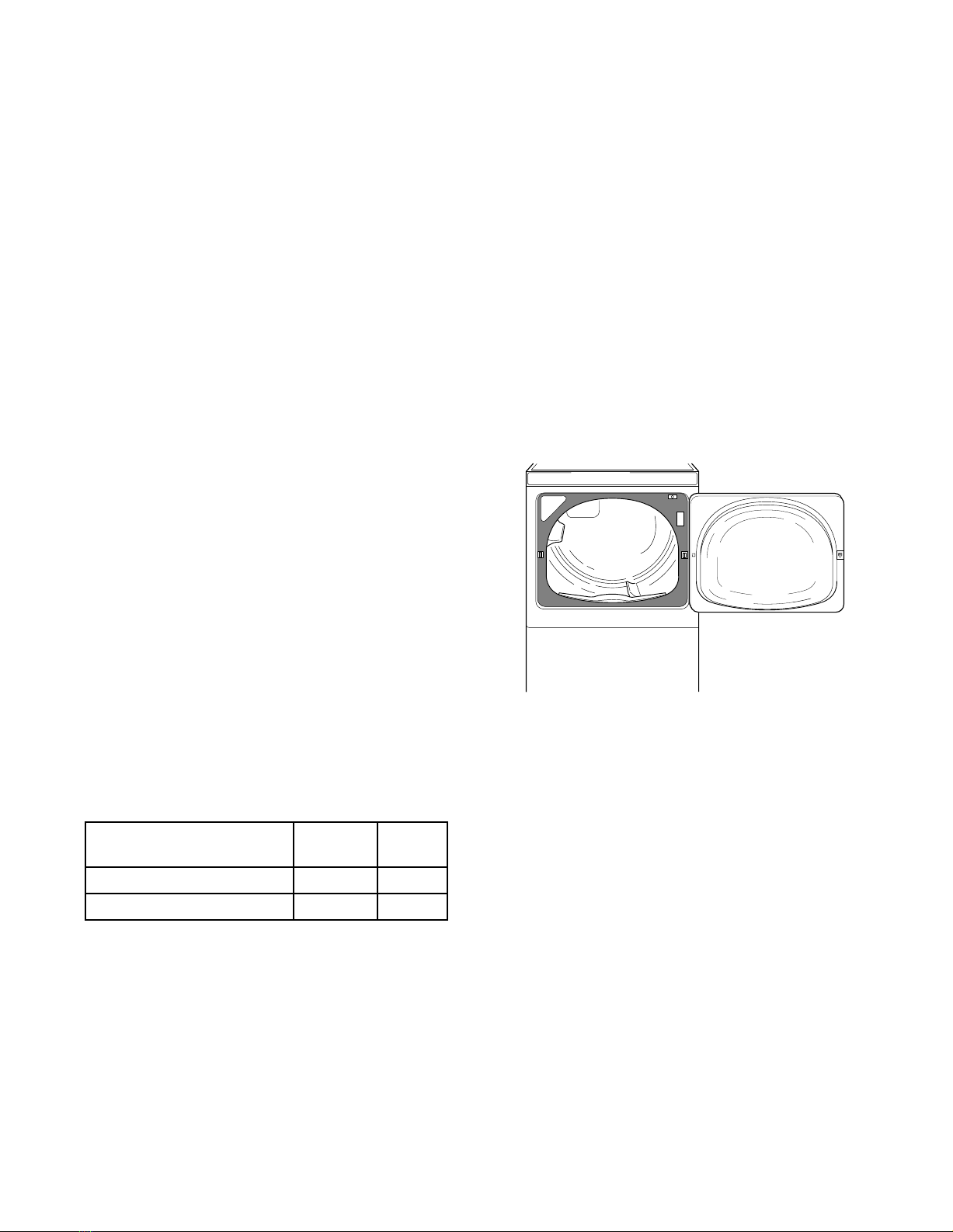
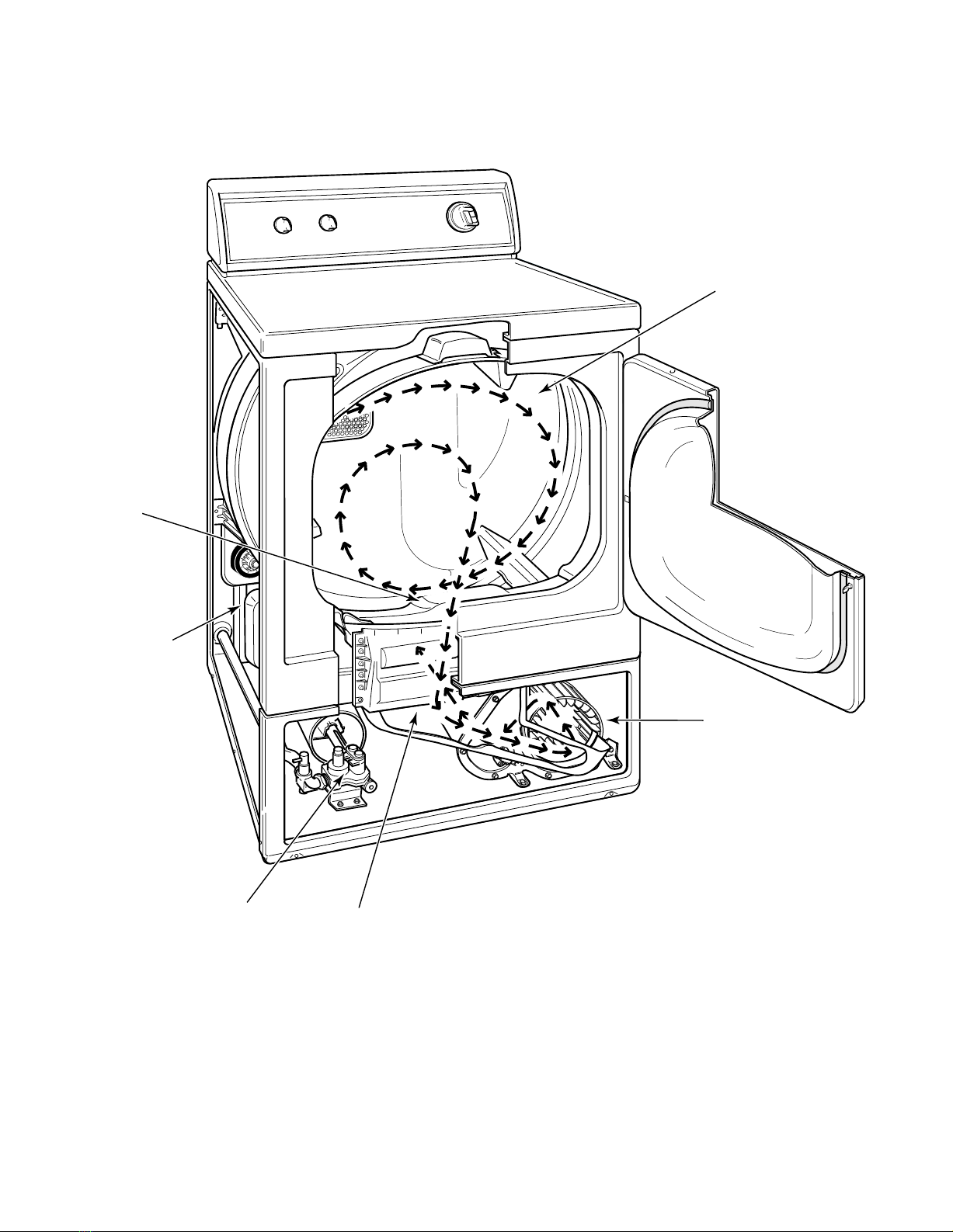
How Your Dryer Works...........................................6
Section 3 – Troubleshooting..............................7
1. Motor Does Not Run .........................................7
2. Unit Stops In Cycle; Quits After The First Few
Loads; Has A Burning Smell; Cycles On Motor
Thermal Protector ..............................................8
3. Motor Runs But Cylinder Does Not Turn ........9
4. Motor Does Not Stop ........................................9
5. Heating Assembly Does Not Heat Or Burner
Does Not Ignite ...............................................10
6. Igniter Does Not Glow (Gas Supply Sufficient)
(Gas Models)....................................................11
7. Burner Ignites And Goes Out Repeatedly
(Gas Models)....................................................11
8. Igniter Glows But Burner Does Not Ignite
(Gas Models)....................................................11
9. Heater Assembly Or Burner
Shuts Off Prematurely......................................12
10. Heater Assembly Or Burner Repeatedly
Cycles Off On Limit Thermostat.....................12
11. Heater Assembly Or Burner
Does Not Shut Off ...........................................13
12. Clothes Do Not Dry.........................................13
13. Timer Does Not Advance In Automatic Cycle14
14. Clothes Are Too Hot When
Removed From Dryer ......................................15
15. Ignition Control Flashes ..................................16
Section 4 – Grounding.....................................19
16. Ground Wires From Terminal Block To Rear
Bulkhead And From Rear Bulkhead To Cabinet
Top And Control Panel....................................19
17. Ground Wires From Rear Bulkhead To Cabinet
Top And Control Panel....................................19
18. Ground Wires From Dryer Base To Wire
Harness And To Ignition Control . ..................20
Section 5 – Service Procedures.......................21
19. Control Hood Assembly..................................21
20. Control Hood End Caps...................................21
21. Graphic Panel...................................................21
22. Timer ...............................................................21
23. Fabric Selector Switch.....................................22
24. Signal...............................................................22
25. Access Panel....................................................24
26. Lint Filter.........................................................25
27. Loading Door And Door Hinge.......................25
28. Inner And Outer Door Panels And Door Pull..26
29. Door Strike ......................................................28
30. Door Seal.........................................................28
31. Front Panel And Panel Seal.............................29
32. Door Switch.....................................................29
33. Door Catch.......................................................29
34. Door Hinge ......................................................31
35. Hold-down Clips And Locators.......................31
36. Burner System Components (Gas Models) .....32
37. Burner Housing And Heat Shroud
(Gas Models)....................................................33
38. Limit Thermostat (Gas Models) ......................34
39. Heating Element (Electric Models).................34
40. Thermostat And Heater....................................35
41. Air Duct...........................................................35
42. Motor And Exhaust Assembly ........................36
43. Cabinet Top .....................................................39
44. Front Bulkhead Assembly ...............................40
45. Cylinder Belt....................................................42
46. Cylinder Assembly ..........................................43
47. Cylinder Rollers...............................................45
48. Outlet Cover ....................................................45
49. Rear Bulkhead And Heater Box......................46
50. Terminal Block Or Power Cord.......................48
51. Cabinet.............................................................50
52. Base .................................................................51
Section 6 – Adjustments ..................................53
53. Leveling Legs ..................................................53
54. Burner Flame (Gas Models) ............................54

2505714
Section 7 – Test Procedures ............................55
55. Drive Motor.....................................................55
56. Burner System Operation
– Silicon Nitrate Ignition .................................58
57. Electrical Circuit To Ignition System
– Silicon Nitrate Ignition .................................58
58. Gas Valve Coils Check
– Silicon Nitrate Ignition .................................59
59. Flame Sensor Check
– Silicon Nitrate Ignition .................................60
60. Igniter Check – Silicon Nitrate Ignition ..........60
61. Ignition Control – Silicon Nitrate Ignition ......60
62. Thermal Fuse (Electric Models)......................61
63. Heater Assembly (Electric Models).................61
64. Cycling Or Limit Thermostat ..........................61
65. Fabric Selector Switch.....................................62
66. Signal...............................................................62
67. Timer Advance And Timer Contact Points.....62
68. Door Switch.....................................................63
Section 8 –
Internal Wiring Of Dryer Motor Switch.......65

505714 3
Section 1
Safety Information
Throughout this manual and on machine decals, you will find precautionary statements (“CAUTION,”
“WARNING,” and “DANGER”) followed by specific instructions. These precautions are intended for the
personal safety of the operator, user, servicer, and those maintaining the machine.
aDANGER
Danger indicates the presence of a hazard that will cause severe personal injury, death, or substantial
property damage if the danger is ignored.
aWARNING
Warning indicates the presence of a hazard that can cause severe personal injury, death, or substantial
property damage if the warning is ignored.
aCAUTION
Caution indicates the presence of a hazard that will or can cause minor personal injury or property
damage if the caution is ignored.
Additional precautionary statements (“IMPORTANT” and “NOTE”) are followed by specific instructions.
IMPORTANT
The word “IMPORTANT” is used to inform the reader of specific procedures where minor machine
damage will occur if the procedure is not followed.
NOTE
The word “NOTE” is used to communicate installation, operation, maintenance or servicing information
that is important but not hazard related.
In the interest of safety, some general precautions relating to the operation of this machine follow.
• Failure to install, maintain, and/or operate this product according to the manufacturer’s
instructions may result in conditions which can produce serious injury, death and/or property
damage.
• Do not repair or replace any part of the product or attempt any servicing unless specifically
recommended or published in this Service Manual and that you understand and have the
skills to carry out.
• Whenever ground wires are removed during servicing, these ground wires must be
reconnected to ensure that the product is properly grounded and to reduce the risk of fire,
electric shock, serious injury, or death. W006R1
WARNING

4505714
Section 1 Safety Information
NOTE: The WARNINGS and IMPORTANT INSTRUCTIONS appearing in this manual are not meant to
cover all possible conditions and situations that may occur. Common sense, caution and care must be
exercised when installing, maintaining or operating the dryer.
Always contact your dealer, distributor, service agent or the manufacturer about any problems or conditions you do
not understand.
Locating an Authorized Servicer:
Alliance Laundry Systems LLC is not responsible for personal injury or property damage resulting from improper
service. Review all service information before beginning repairs.
Warranty service must be performed by an authorized technician, using authorized factory parts. If service is
required after the warranty expires, Alliance Laundry Systems LLC also recommends contacting an authorized
technician and using authorized factory parts.
To reduce the risk of electric shock, fire, explosion, serious injury or death:
• Disconnect electric power to the dryer(s) before servicing.
• Close gas shut-off valve to gas dryer(s) before servicing.
• Never start the dryer(s) with any guards/panels removed.
• Whenever ground wires are removed during servicing, these ground wires must be
reconnected to ensure that the dryer is properly grounded. W001R1
WARNING
Repairs that are made to your products by unqualified persons can result in hazards due to
improper assembly or adjustments subjecting you, or the inexperienced person making such
repairs, to the risk of serious injury, electrical shock, or death. W007
WARNING
If you or an unqualified person perform service on your product, you must assume the
responsibility for any personal injury or property damage which may result. The manufacturer
will not be responsible for any injury or property damage arising from improper service and/or
service procedures. W008
WARNING

505714 5
Section 2
Introduction
Customer Service
If service is required, contact Kleenmaid Customer
Care Centre at:
Kleenmaid
P.O. Box 5560
Maroochydore South QLD 4558
or Phone FREECALL 1-800-817-479
Nameplate Location
When calling or writing about your product, be sure to
mention model and serial numbers. Model and serial
numbers are located on nameplate(s) as shown.
Model Identification
Information in this manual is applicable to these
dryer models.
* Add Letter To Designate Color. L – Almond W – White
D294S
Model Number Electric
Heat Gas
Heat
LEK33A*-4350 X
LGK33A*-3058 X

6505714
Section 2 Introduction
How Your Dryer Works
The dryer uses heated air to dry loads of laundry. When the motor is started, the exhaust fan pulls room temperature
air in through louvers at the rear of the dryer and over the heat source (burner flame for gas and heating element for
electric). The heated air moves through the heater duct and into the cylinder, where it circulates through the wet load.
The air then passes through the lint filter, air duct, and exhaust fan, where it is vented to the outdoors.
CYLINDER
EXHAUST
FAN
GAS
VALVE
HEATER
DUCT
LINT
FILTER
AIR DUCT D282SE3A

505714 7
To reduce the risk of electric shock, fire, explosion, serious injury or death:
• Disconnect electric power to the dryer(s) before servicing.
• Close gas shut-off valve to gas dryer(s) before servicing.
• Never start the dryer(s) with any guards/panels removed.
• Whenever ground wires are removed during servicing, these ground wires must be
reconnected to ensure that the dryer is properly grounded. W001R1
WARNING
Section 3
Troubleshooting
IMPORTANT: Refer to appropriate Model Wiring Diagram for aid in testing dryer components.
1. MOTOR DOES NOT RUN
POSSIBLE CAUSE TO CORRECT
Electrical power off, fuse blown, or power cord not
plugged in. • Check laundry room for blown or loose fuse(s), or open
circuit breaker(s). The dryer itself does not have an
electrical fuse.
• Check both fuses for electric models.
Loading door not closed. • Close door.
Inoperative door switch. • Test switch and replace if inoperative.
Timer improperly set. • Reset timer, or try another cycle.
Inoperative timer. • Test timer and replace if inoperative.
Motor starting functions inoperative.
Doesn’t start; or motor just hums. • Refer to Paragraph 55 to check motor switch and motor
windings.
Motor is dead, won’t run. • Refer to Paragraph 55 to check motor switch, motor
windings, and main windings.
Motor overload protector has cycled. • Wait two or three minutes for overload protector to reset.
If protector cycles repeatedly, refer to Paragraph 2.
Motor centrifugal switch sticky or plugged with
lint. • Removedust orlintandspraywith“SLYDE,”No. 131P4,
to clean and lubricate.
Bind in motor bearing. • Remove belts and determine if motor shaft will spin.
• Replace motor if shaft is locked up.
Loose motor wire harness connection block. • Firmly press connection block onto motor switch.
Broken, loose, or incorrect wiring. • Refer to wiring diagram.
Power cord is miswired. • Refer to wiring diagram for the correct wiring.

8505714
Section 3 Troubleshooting
To reduce the risk of electric shock, fire, explosion, serious injury or death:
• Disconnect electric power to the dryer(s) before servicing.
• Close gas shut-off valve to gas dryer(s) before servicing.
• Never start the dryer(s) with any guards/panels removed.
• Whenever ground wires are removed during servicing, these ground wires must be
reconnected to ensure that the dryer is properly grounded. W001R1
WARNING
2. UNIT STOPS IN CYCLE; QUITS AFTER THE FIRST FEW LOADS; HAS A BURNING SMELL;
CYCLES ON MOTOR THERMAL PROTECTOR
POSSIBLE CAUSE TO CORRECT
Incorrect voltage. • See nameplate in door well for correct voltage.
• Refer to INSTALLATION INSTRUCTIONS (supplied
with dryer) for electrical requirements.
Clothes load too large. • Remove part of load. Maximum load: dryer cylinder one
half full of wet clothes.
Clothes cylinder is binding. • Check cylinder for binding and “out of round” condition.
• Check front and rear bulkheads for warping.
• Check support rollers for binding.
• Check cylinder seals and glides for wear or damage.
• Check for clothes lodged between cylinder baffle and
bulkhead.
Broken, loose or incorrect wiring. • Refer to wiring diagram.
Motor switch functions inoperative. Short in motor
winding. • Refer to Paragraph 55 to check switch and windings.
Clothes caught in fan. • Check fan for obstruction.

505714 9
Section 3 Troubleshooting
To reduce the risk of electric shock, fire, explosion, serious injury or death:
• Disconnect electric power to the dryer(s) before servicing.
• Close gas shut-off valve to gas dryer(s) before servicing.
• Never start the dryer(s) with any guards/panels removed.
• Whenever ground wires are removed during servicing, these ground wires must be
reconnected to ensure that the dryer is properly grounded. W001R1
WARNING
3. MOTOR RUNS BUT CYLINDER DOES NOT TURN
4. MOTOR DOES NOT STOP
POSSIBLE CAUSE TO CORRECT
Motor drive pulley loose. • Tighten pulley.
Belt not installed on pulley. • Install belt. Refer to Figure 20.
Broken cylinder belt. • Replace belt.
Clothes cylinder is binding. • Check cylinder for binding and “out of round” condition.
• Check front and rear bulkheads for warping.
• Check cylinder rollers for binding.
• Check cylinder seals and glides for wear or damage.
Broken, weak or disconnected idler lever spring. • Replace or reconnect spring. Refer to Figure 21.
Belt routed on wrong side of idler lever. • Reroute belt. Refer to Figure 20.
Oil on cylinder. • Wipe oil from cylinder.
Belt is “inside out.” • Reinstall belt with ribbed surface against cylinder.
Idler arm is binding. • Add grease between idler arm and motor mount.
• Replace idler arm and bolt if needed.
Dryer is overloaded. • Remove some laundry from dryer.
Wrong motor. • Refer to parts manual for correct motor part number.
Wrong belt used on dryer. • Check belt part number against correct part number in the
Parts manual.
• Replace belt if needed.
Bent idler arm. • Replace idler arm.
POSSIBLE CAUSE TO CORRECT
Incorrect wiring to motor switch. • Refer to wiring diagram.
Motor centrifugal switch sticky or plugged with
lint. • Remove dust or lint and spray with “SLYDE,” Part No.
131P4, to clean and lubricate.
Inoperative door switch. • Test switch and replace if inoperative.
Inoperative timer – nonmetered models. • Test timer and replace if inoperative.

10 505714
Section 3 Troubleshooting
To reduce the risk of electric shock, fire, explosion, serious injury or death:
• Disconnect electric power to the dryer(s) before servicing.
• Close gas shut-off valve to gas dryer(s) before servicing.
• Never start the dryer(s) with any guards/panels removed.
• Whenever ground wires are removed during servicing, these ground wires must be
reconnected to ensure that the dryer is properly grounded. W001R1
WARNING
5. HEATING ASSEMBLY DOES NOT HEAT OR BURNER DOES NOT IGNITE
POSSIBLE CAUSE TO CORRECT
Improper or inadequate exhaust system. • See INSTALLATION INSTRUCTIONS (supplied with
dryer) for exhaust requirements.
Use of plastic or thin foil exhaust duct. • Replace with solid or rigid flexible metal exhaust duct.
Blown house fuse or tripped circuit breaker. • Check fuses or circuit breakers. A 240 Volt dryer uses two
fuses. Make sure both fuses are good.
Temperature selector switch set at FLUFF, or
inoperative. • Reset or test switch and replace if inoperative.
Timer improperly set (set in a cool-down period, or
a no heat cycle). • Reset timer. Try another cycle.
Inoperative limit thermostat. • Test thermostat and replace if inoperative.
Inoperative drive motor switch. • Test switch and replace if inoperative.
Electric Models: Inoperative heater assembly. • Test heater assembly and replace if cold Ohms do not read
between 9 and 10.5 Ohms.
Electric Models: Inoperative thermal fuse. • Test thermal fuse and replace if inoperative.
Gas Models: Insufficient gas supply. • Check gas shut-off valve in dryer and main gas line valve.
• Open partially closed gas shut-off valve, or correct low
gas pressure.
Gas Models: Inoperative gas valve coils. • Test coils (Paragraph 58) and replace if inoperative.
Gas Models: Inoperative flame sensor. • Test flame sensor (Paragraph 59) and replace if
inoperative.
Gas Models: Inoperative igniter. • Test igniter (Paragraph 60) and replace if inoperative.
Gas Models: Harness not properly connected to gas
controls. • Check harness connections to gas valve coils, sensor and
main harness.
• Reconnect as required.
Gas Models: Restricted gas flow in gas orifice. • Clean out gas orifice.
Gas Models: Tripped high limit thermostat. • Reset thermostat.
Inoperative cycling thermostat. • Test thermostat and replace if inoperative.
Inoperative timer. • Test timer and replace if inoperative.
Broken, loose, or incorrect wiring. • Refer to wiring diagram.

505714 11
Section 3 Troubleshooting
To reduce the risk of electric shock, fire, explosion, serious injury or death:
• Disconnect electric power to the dryer(s) before servicing.
• Close gas shut-off valve to gas dryer(s) before servicing.
• Never start the dryer(s) with any guards/panels removed.
• Whenever ground wires are removed during servicing, these ground wires must be
reconnected to ensure that the dryer is properly grounded. W001R1
WARNING
6. IGNITER DOES NOT GLOW (GAS SUPPLY SUFFICIENT) (GAS MODELS)
7. BURNER IGNITES AND GOES OUT REPEATEDLY (GAS MODELS)
8. IGNITER GLOWS BUT BURNER DOES NOT IGNITE (GAS MODELS)
POSSIBLE CAUSE TO CORRECT
No power to power leads on valve. • Check timer, selector switch, thermostats, motor switch,
and wiring.
Flame sensor failed with contacts open. • Replace flame sensor.
Igniter broken or open. • Replace igniter.
POSSIBLE CAUSE TO CORRECT
Improper or inadequate exhaust system. Weather
hood flapper restricted. • See INSTALLATION INSTRUCTIONS (supplied with
dryer) for exhaust requirements.
Insufficient gas supply. • Check gas supply and pressure.
• Make sure gas shut-off valve is turned on.
Cracked igniter. • Replace igniter and bracket.
Inoperative or intermittent gas valve coils. • Check coils (Paragraph 58) and replace appropriate coils.
POSSIBLE CAUSE TO CORRECT
Open secondary coil or holding coil. • Replace gas valve (in-warranty), or replace coils
(out-of-warranty). Refer to Paragraph 58.
Insufficient gas supply. • Check gas supply and pressure.
• Make sure gas shut-off valve is turned on.
Igniter and bracket installed improperly on burner
tube assembly. • Loosen screw and properly position igniter and bracket on
burner tube assembly.

12 505714
Section 3 Troubleshooting
To reduce the risk of electric shock, fire, explosion, serious injury or death:
• Disconnect electric power to the dryer(s) before servicing.
• Close gas shut-off valve to gas dryer(s) before servicing.
• Never start the dryer(s) with any guards/panels removed.
• Whenever ground wires are removed during servicing, these ground wires must be
reconnected to ensure that the dryer is properly grounded. W001R1
WARNING
9. HEATER ASSEMBLY OR BURNER SHUTS OFF PREMATURELY
10. HEATER ASSEMBLY OR BURNER REPEATEDLY CYCLES OFF ON LIMIT THERMOSTAT
POSSIBLE CAUSE TO CORRECT
Improper or inadequate exhaust system.
Weather hood flapper restricted. • See INSTALLATION INSTRUCTIONS (supplied with
dryer) for exhaust requirements.
Gas Models: Insufficient gas supply. • Check main gas line shut-off valve.
• Open partially closed gas shut-off valve, or correct low
pressure.
Gas Models: Dryer not properly equipped for type
of gas used. • Refer to “Gas Burner Conversion Procedures” supplied in
gas burner conversion kit.
Gas Models: Improperly adjusted burner flame. • Adjust flame. Refer to Paragraph 54.
Cycling off on limit thermostat. • Momentarily connect a jumper wire across thermostat
terminals. If heater element heats or burner ignites when
jumper wire is connected, refer to Paragraph 10.
Gas models: Flame sensor contact closing. • Replace flame sensor (Paragraph 36, step “d”) or adjust
burner flame. Refer to Paragraph 54.
Inoperative cycling thermostat. • Test thermostat and replace if inoperative.
Inoperative timer. • Test timer and replace if inoperative.
Broken, loose, or incorrect wiring. • Refer to wiring diagram.
POSSIBLE CAUSE TO CORRECT
External exhaust system longer or providing greater
restriction than recommended. • Refer to INSTALLATION INSTRUCTIONS (supplied
with dryer) for exhaust system requirements.
Use of plastic or thin foil exhaust duct. • Replace with solid or rigid flexible metal exhaust duct.
Clogged lint filter. • Clean lint filter.
Lint in internal dryer ductwork. • Disassemble dryer ductwork and clean.
Lint or other obstruction in external exhaust system. • Disassemble and clean exhaust system.
Hinged damper on exhaust system weather hood
not free to open. • Free hinged damper or replace weather hood.
Limit thermostat cycling at too low a temperature. • Replace thermostat. Refer to Paragraph 38.
Air leak around loading door. (Door not sealing due
to damaged seal or inoperative door catch.) • Replace seal or catch.
Air leak at blower seal. • Check and replace seal if necessary.
Air leak at cylinder seal(s). • Check and replace seal(s) if necessary.

505714 13
Section 3 Troubleshooting
To reduce the risk of electric shock, fire, explosion, serious injury or death:
• Disconnect electric power to the dryer(s) before servicing.
• Close gas shut-off valve to gas dryer(s) before servicing.
• Never start the dryer(s) with any guards/panels removed.
• Whenever ground wires are removed during servicing, these ground wires must be
reconnected to ensure that the dryer is properly grounded. W001R1
WARNING
11. HEATER ASSEMBLY OR BURNER DOES NOT SHUT OFF
12. CLOTHES DO NOT DRY
POSSIBLE CAUSE TO CORRECT
Inoperative motor switch. (Timer must be in a heat
setting.) • Test switch and replace if inoperative.
Motor does not stop. • Refer to Paragraph 4.
Incorrect wiring. • Refer to wiring diagram.
Heater assembly shorted. • Remove heater assembly and check for short.
POSSIBLE CAUSE TO CORRECT
Heater assembly does not heat or burner does not
ignite. • Refer to Paragraph 5.
Too much water in articles being dried. • Remove excess water.
Laundry load too large. • Remove part of load. Maximum load: Dryer cylinder one
half full of wet clothes.
Laundry load too small. • Add one or two bath towels to load.
Excessive lint on lint filter. • Clean lint filter.
Automatic cycle. • Adjust timer knob to More Dry setting.
Heat selector switch or timer set on FLUFF or
inoperative. • Reset switch or timer, or test and replace the switch or
timer if inoperative.
Improper or inadequate exhaust system. • See INSTALLATION INSTRUCTIONS (supplied with
dryer) for exhaust requirements.
Heater assembly or burner shuts off prematurely. • Refer to Paragraph 9.
Gas Models: Gas line pressure too high or too low. • If Natural Gas line pressure to dryer exceeds 8 inch water
columnpressure, orislower than4 inch watercolumn, ask
Gas Company to correct.
Improper belt installation (low RPM). • Check for proper installation. Refer to Figure 20.

14 505714
Section 3 Troubleshooting
To reduce the risk of electric shock, fire, explosion, serious injury or death:
• Disconnect electric power to the dryer(s) before servicing.
• Close gas shut-off valve to gas dryer(s) before servicing.
• Never start the dryer(s) with any guards/panels removed.
• Whenever ground wires are removed during servicing, these ground wires must be
reconnected to ensure that the dryer is properly grounded. W001R1
WARNING
13. TIMER DOES NOT ADVANCE IN AUTOMATIC CYCLE
POSSIBLE CAUSE TO CORRECT
Inoperative cycling thermostat. • Test thermostat and replace if inoperative.
Inoperative resistor (Electric Models). • Test resistor (Paragraph 67, step “d”) and replace if
inoperative.
Heater assembly does not heat or burner does not
ignite. • Refer to Paragraph 5.
Heater assembly or burner cycles off prematurely. • Refer to Paragraph 9.
Improper or inadequate exhaust system. • Refer to INSTALLATION INSTRUCTIONS (supplied
with dryer) for exhaust requirements.
Drying large load. • Timer will not advance until the load is almost dry.
Broken, loose or incorrect wiring. • Refer to wiring diagram.
Timer motor is inoperative. • Select a drying cycle and activate start switch.
• Rotate timer knob until signal sounds.
• Release timer knob.
• Signal should stop within ten minutes. If not, replace
timer.
• Refer to Paragraph 67.
Inoperative seals (air leaks). • Check and replace any inoperative seals in the following
areas:
1. Seal between loading door and front panel.
2. Seal between front panel and front bulkhead.
3. Seal between blower cover and air duct.
4. Seal between cylinder and front or rear bulkhead.
5. Seal between upper and lower air ducts.

505714 15
Section 3 Troubleshooting
To reduce the risk of electric shock, fire, explosion, serious injury or death:
• Disconnect electric power to the dryer(s) before servicing.
• Close gas shut-off valve to gas dryer(s) before servicing.
• Never start the dryer(s) with any guards/panels removed.
• Whenever ground wires are removed during servicing, these ground wires must be
reconnected to ensure that the dryer is properly grounded. W001R1
WARNING
14. CLOTHES ARE TOO HOT WHEN REMOVED FROM DRYER
POSSIBLE CAUSE TO CORRECT
Improper or inadequate exhaust system. • Refer to INSTALLATION INSTRUCTIONS (supplied
with dryer) for exhaust requirements.
Clothes are removed from dryer before cycle has
completed. • Allow the dryer to complete the cycle through the cool-
down to the OFF position.
Inoperative cycling thermostat. Inoperative
thermostat heater on the DELICATE setting. • Test cycling thermostat or thermostat heater and replace if
inoperative.
Inoperative timer (not allowing cool-down). • Test timer and replace if inoperative.
Inoperative seals (air leaks). • Check and replace any inoperative seals in the following
areas:
1. Seal between loading door and front panel.
2. Seal between front panel and front bulkhead.
3. Seal between blower cover and air duct.
4. Seal between cylinder and front or rear bulkhead.
5. Seal between upper and lower air ducts.

16 505714
Section 3 Troubleshooting
To reduce the risk of electric shock, fire, explosion, serious injury or death:
• Disconnect electric power to the dryer(s) before servicing.
• Close gas shut-off valve to gas dryer(s) before servicing.
• Never start the dryer(s) with any guards/panels removed.
• Whenever ground wires are removed during servicing, these ground wires must be
reconnected to ensure that the dryer is properly grounded. W001R1
WARNING
15. IGNITION CONTROL FLASHES
(Figure 1)
NOTE: This control will lock-out the igniter after four failed attempts at ignition. The control can be reset by
opening loading door, waiting 1 minute, then closing loading door.If door is closed before waiting 1 minute, the
control will re-enter lockout. The red light will flash a “Flash Code” when the control is in the lock-out mode. The
light will flash on for 1/4 second then off for 1/4 second for each number. The pause between flash codes is 2
seconds. These flashes are caused by the control’s diagnostic test and can be interpreted by reading the following:
FLASH
CODE POSSIBLE CAUSE TO CORRECT
Constant
Light Internal failure. • Reset dryer. If condition persists, then replace
control.
One
Flash Air in gas line. • Purge air from gas line.
Flame sensor coated with Aluminum
Oxide. • Wipe sensor clean or replace sensor if necessary.
Incorrect gas pressure. • Check for correct gas pressure. If gas pressure is
incorrect, then contact local gas company.
Gas shut-off valve closed. • Open gas shut-off valve.
Four
Flashes Internal failure. • Reset dryer. If condition persists, then replace
control.
Loose or disconnected wiring. • Check all wiring leading to, or coming from, the
control module for secure connections.
Open Igniter/igniter sensing circuit/voltage
measurement circuit. • Check igniter and all circuits, replace if necessary.
Five
Flashes Loose or disconnected wiring. • Check all wiring leading to, or coming from, the
control module for secure connections.
Inoperative gas valve. • Check gas valve and replace if necessary.
Inoperative flame sensor. • Replace flame sensor/igniter.
Six
Flashes Loose or disconnected wiring. • Check all wiring leading to, or coming from, the
control module for secure connections.
Incorrect wiring. • Check wiring diagram and make sure dryer is
wired correctly.
Incorrect polarity. • Contact a professional electrician to check the
polarity, and correct any problems.
Seven
Flashes Loose or disconnected wiring. • Check all wiring leading to, or coming from, the
control module for secure connections.
Flame sensor and/or appliance not properly
grounded. • Check grounding from control to base, and from
lead in cord to dryer.
continued

505714 17
Section 3 Troubleshooting
To reduce the risk of electric shock, fire, explosion, serious injury or death:
• Disconnect electric power to the dryer(s) before servicing.
• Close gas shut-off valve to gas dryer(s) before servicing.
• Never start the dryer(s) with any guards/panels removed.
• Whenever ground wires are removed during servicing, these ground wires must be
reconnected to ensure that the dryer is properly grounded. W001R1
WARNING
Rapid
Flashing Incorrect frequency. • Contact a professional electrician to check the
frequency, and correct any problems. Power
supply must be 50 – 60 Hz. 2-wire, plus
grounding (earth) wire.
Figure 1
FLASH
CODE POSSIBLE CAUSE TO CORRECT
WR WHITE - ROGERS DIV.
EMERSON ELECTRIC CO.
DISCONNECT POWER
BEFORE SERVICING
DISCONNECT POWER
BEFORE SERVICING
DISCONNECT POWER
BEFORE SERVICING
DISCONNECT POWER
BEFORE SERVICING
DISCONNECT POWER
BEFORE SERVICING
DISCONNECT POWER
BEFORE SERVICING
DISCONNECT POWER
BEFORE SERVICING
DISCONNECT POWER BEFORE
SERVICINGGDGHDHJD DHJD DHD HD
HD HD HDGFJGFKGK GFJHGJ FHFH
F KJFJF KH GJHJF JDAPALS DK KF
DISCONNECT POWER BEFORE
SERVICING SERVICEING OK
IMPORTANT
DIAGNOSTIC INDICATOR
MODEL 50A72-203.
WARNING
WR
CONTROL
RED
LIGHT
D194SE3B

18 505714
Section 3 Troubleshooting Notes
This manual suits for next models
1
Table of contents
Other Kleenmaid Dryer manuals

Kleenmaid
Kleenmaid LEK33AW-4350 User manual

Kleenmaid
Kleenmaid LDVF70 User manual

Kleenmaid
Kleenmaid KED600 User manual

Kleenmaid
Kleenmaid KED601 User manual

Kleenmaid
Kleenmaid KED2000 Setup guide

Kleenmaid
Kleenmaid KCDV60 Installation guide

Kleenmaid
Kleenmaid KED300-Compact User manual

Kleenmaid
Kleenmaid KED2000 User manual

Kleenmaid
Kleenmaid KED602 User manual

Kleenmaid
Kleenmaid KCDV60 Installation guide