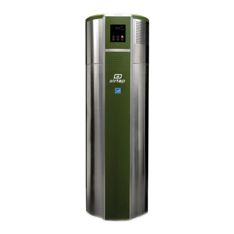
AirTap ATI50 Original instructions

Owner’s Manual &
Installaon Instrucons
AirTap™ Hybrid Water Heater
ATI50 & ATI66
AGATI0811 - RD


TABLE OF CONTENT
CONSUMER
SUPPORT MAINTENANCE OPERATING
INSTRUCTIONS
INSTALLATION
INSTRUCTIONS
SAFETY
INFORMATION
Model #
Serial #
Keep the model and serial number here.
You can nd them on the front side of
your water heater.
Save this Manual with your Model
Number and Serial Number for our
records.
Safety Informaon………………….….4, 5
Installaon Instrucons……………..6-11
Operang Instrucons……………….12-17
Maintenance……………………………..18-21
Consumer Support…………………….22-24
Notes…………………………………………25

4
SAFETY INFORMATION
WARNING!
For your safety, the informaon in this manual must be followed to minimize the risk of re or explosion,
electric shock, or to prevent property damage, personal injury, or loss of life.
Be sure to read and understand the enre Owner’ s Manual before aempng to install or operate this water heater. It
may save you me and cost. Pay parcular aenon to the Safety Instrucons. Failure to follow these warnings could
result in serious bodily injury or death. Should you have problems understanding the instrucons in this manual, or
have any quesons, STOP and get help from a qualied service technician or the local electric ulity.
WATER TEMPERATURE ADJUSTMENT
Safety and energy conservaon are factors to be considered when selecng the water temperature seng via the
water heater’s user interface. Water temperatures above 125°F can cause severe burns or death from scalding. Be sure
to read and follow the warnings outlined on the label pictured below. This label is also located on the water heater
near the top of the tank.
Temperature Time to Produce a Serious Burn
120°F More than 5 minutes
125°F 1-1/2 to 2 minutes
130°F About 30 seconds
135°F About 10 seconds
140°F Less than 5 seconds
145°F Less than 3 seconds
150°F About 1-1/2 seconds
155°F About 1 second
160°F Instantaneously
Time/Temperature Relaonship in Scalds
Table courtesy of Shriners Burn Instute
The chart shown above may be used as a guide in determining the
proper water temperature for your home.
NOTE: Household with small children, disabled or elderly persons
may require a 120°F of lower thermostat seng to prevent contact
with “HOT” water.
DANGER: There is a Hot Water SCALD Potenal if the
control water temperature is set too high.
Mixing valves for reducing point of use water temperature by
mixing hot and cold water in branch water lines are available.
Contact a licensed plumber or the local plumbing authority for
further informaon.
CONSUMER
SUPPORT MAINTENANCE OPERATING
INSTRUCTIONS
INSTALLATION
INSTRUCTIONS
SAFETY
INFORMATION

5
SAFETY INFORMATION
CONSUMER
SUPPORT MAINTENANCE OPERATING
INSTRUCTIONS
INSTALLATION
INSTRUCTIONS
SAFETY
INFORMATION
WARNING!
Gasoline, as well as other ammable materials and liquids (adhesives, solvents, etc.), and the vapors they produce, are
extremely dangerous. DO NOT handle, use or store gasoline or other ammable or combusble materials anywhere
near or in the vicinity of a water heater. Be sure to read and follow the warning label pictured below and other labels
on the water heater, as well as the warnings printed in this manual. Failure to do so can result in property damage,
bodily injury, or death.
For Installaons in the State of California
California Law requires that residenal water heaters must be braced, anchored or strapped to resist falling or
horizontal displacement due to earthquake moons. For residenal water heaters up to 52 gallon capacity, a brochure
with generic earthquake bracing instrucons can be obtained from: Oce of the State Architect, 400 P Street,
Sacramento, CA 95814 or you may call 916-324-5315 or ask a water heater dealer.
However, applicable local codes shall govern installaon. For residenal water heaters of a capacity greater than 52
gallons, consult the local building jurisdicon for acceptable bracing procedures.
California Proposion 65 Warning: This product contains chemicals known to the State of California to cause
cancer, birth defects or other reproducve harm.

6
INSTALLATION INSTRUCTIONS
CONSUMER
SUPPORT MAINTENANCE OPERATING
INSTRUCTIONS
INSTALLATION
INSTRUCTIONS
SAFETY
INFORMATION
A. LOCATION REQUIREMENTS
CAUTION: This unit is to be installed indoors only.
Install unit in a clean, unobstructed, at and dry area. Ensure hot water lines are insulated to minimize energy waste.
Ensure that the unit and water lines are protected from corrosive condions and freezing temperatures.
WARNING:
This unit should not be located in an area where water leakage can damage adjacent area or lower oors of the
structure. To avoid potenal damage from water leakage, place the unit over a suitably sized drain pan and ensure that
the drain pan is unblocked and adequately drained. It is recommended that the drain pain has at least 2 inches of clear
space all around the unit’s circumference. Ensure that the unit is securely placed on the drain pan and the drain pan
itself is securely placed on the ground. The unit should stand vercal, without any incline.
WARNING:
The unit should not be installed in a space where liquids give o ammable vapors or where such liquids are used or
stored. Such liquids include gasoline, LP gas (butane and propane), paints or adhesives and their thinners, solvents or
removers. Because of natural air movement in a room or other enclosed space, ammable vapors can be carried from
where their liquids are being used or stored. The arc drawn within the unit’s control can ignite these vapors causing an
explosion or re which may result in severe burns or death to those in range as well as property damage.

7
INSTALLATION INSTRUCTIONS
CONSUMER
SUPPORT MAINTENANCE OPERATING
INSTRUCTIONS
INSTALLATION
INSTRUCTIONS
SAFETY
INFORMATION
B. DIMENSION, SPACE REQUIREMENT AND VENTILATION
Please check dimensions for the model you intend to install and ensure that you have at least 2 feet of clearance
around the unit as well as on top of the unit.
If the unit is installed in an enclosed room:
a. The room size should exceed 1,000 cubic feet OR
b. The room must have a louvered door or similar venlaon OR
c. The unit must be ducted to vent the exhaust air out of the enclosed area.
2’
2’
2’
D
H
ATI50 ATI66
Height (H) 58.3” 69.3”
Diameter (D) 25.6” 25.6”
Weight (lbs) 190 227
C. LOCAL INSTALLATION REGULATIONS
This water heater must be installed in accordance with these instrucons, local codes, ulity codes, ulity company
requirements or, in the absence of local codes, the latest edion of the Naonal Electrical Code. It is available from
some local libraries or can be purchased from the Naonal Fire Prevenon Associaon, Baerymarch Park, Quincy, MA
02169 as booklet ANSI/NFPA 70.
D. ELECTRICAL REQUIREMENTS
Unit must be connected to a dedicated 240V/60Hz single phase power outlet rated for at least 30 amperes. Conrm
that this power outlet is not being shared with another appliance.
Fig. 1 Fig. 2

8
INSTALLATION INSTRUCTIONS
D. ELECTRICAL REQUIREMENTS (CONT.)
A separate branch circuit with copper conductors, overcurrent protecve device and suitable disconnecng means
must be provided by a qualied electrician. All wiring must conform to local codes or latest edion of Naonal
Electrical Code ANSI/NFPA 70.
The branch circuit wiring should include either:
1. Metallic conduit or metallic sheathed cable approved for use as a grounding conductor and installed with ngs
approved for the purpose
2. Nonmetallic sheathed cable, metallic conduit or metallic sheathed cable not approved for use as a ground
conductor shall include a separate conductor for grounding. It should be aached to the ground terminals of the
water heater and the electrical distribuon box.
WARNING:
Proper ground connecon is essenal. The presence of water in the piping and water heater does not provide
sucient conducon for a ground. Nonmetallic piping, dielectric unions, exible connectors, etc., can cause the
water heater to be electrically isolated.
E. AMBIENT TEMPERATURE REQUIREMENTS
This unit is to be installed in an area where the ambient temperature is within 20°F - 120°F.
F. MOVING THE UNIT
When moving the unit for installaon, please keep the unit as upright as possible. The unit should not be slanted more
than 30 degrees.
G. WATER SUPPLY CONNECTIONS
The Hot and Cold Water connecons are located on the side of the unit and are ¾” NPT. The connecons are marked
on the unit. Installaon of unions/connectors and shut o valve (on the cold water side) is recommended to enable
easier service or maintenance on the unit. Do not apply heat to any connecon.
H. RELIEF VALVE AND DRAIN VALVE
The unit is pre-aached with T&P/relief and drain valves.
CAUTION:
Please check relief valve for damage or defect prior to turning the unit on. A cered plumber should ensure that the
relief valve is installed according to local codes. Connect the outlet of the relief valve to a suitable open drain so that
the discharge water cannot contact live electrical parts or persons and to eliminate potenal water damage. Piping
used should be of a type approved for hot water distribuon. The discharge line must be no smaller than the outlet
of the valve and must pitch downward from the valve to allow complete drainage (by gravity) of the relief valve and
discharge line. The end of the discharge line should not be threaded or concealed and should be protected from
freezing. No valve of any type, restricon or reducer coupling should be installed in the discharge line.
CONSUMER
SUPPORT MAINTENANCE OPERATING
INSTRUCTIONS
INSTALLATION
INSTRUCTIONS
SAFETY
INFORMATION

9
INSTALLATION INSTRUCTIONS
CONSUMER
SUPPORT MAINTENANCE OPERATING
INSTRUCTIONS
INSTALLATION
INSTRUCTIONS
SAFETY
INFORMATION
I. CONDENSATE DRAIN TUBES
The unit has two condensate drains – primary and overow. The overow drain is pre-aached with a hose. A exible
hose for the primary drain is included with the unit. Aach one end of the hose to the primary condensate drain and
the other end to a drain on the oor.
1. Overow Condensate Drain
2. Primary Condensate Drain
Fig. 3

10
INSTALLATION INSTRUCTIONS
J. THERMAL EXPANSION
WARNING:
The water heater should not be installed in a space where liquids which give o ammable vapors are to be used or
stored.
Determine if a check valve exists in the inlet water line. It may have been installed in the cold water line as a
separate backow preventer, or it may be part of a pressure-reducing valve, water meter or water soener. A check
valve located in the cold water inlet line can cause what is referred to as a “closed water system.” A cold water inlet
line with no check valve or backow prevenon device is referred to as an “open” water system.
As water is heated, it expands in volume and creates an increase in the pressure within the water system. This acon is
referred to as “thermal expansion.” In an “open” water system, expanding water which exceeds the capacity of the
water heater ows back into the city main where the pressure is easily dissipated.
A “closed water system,” however, prevents the expanding water from owing back into the main supply line, and the
result of “thermal expansion” can create a rapid and dangerous pressure increase in the water heater and system
piping. This rapid pressure increase can quickly reach the safety seng of the relief valve, causing it to operate during
each heang cycle. Thermal expansion, and the resulng rapid and repeated expansion and contracon of
components in the water heater and piping system, can cause premature failure of the relief valve, and possibly the
heater itself. Replacing the relief valve will not correct the problem!
The suggested method of controlling thermal expansion is to install an expansion tank in the cold water line between
the water heater and the check valve (refer to the illustraon on right). The expansion tank is designed with an air
cushion built in that compresses as the system pressure increases, thereby relieving the over-pressure condion and
eliminang the repeated operaon of the relief valve. Other methods of controlling thermal expansion are also
available. Contact your installing contractor, water supplier or plumbing inspector for addional informaon regarding
this subject.
K. FILLING WATER
WARNING:
The unit must be COMPLETELY lled with water before being turned on. Failure to do so may permanently damage the
unit and will VOID manufacturer’s warranty. To check if the tank is full:
a. Ensure drain valve is shut ghtly
b. Open cold water inlet valve to ll the tank
c. Open hot water faucets slowly to allow air in the tank and piping to vent out
d. Smooth, undisrupted ow of water from the faucets indicates that the tank is full.
Turning the unit on when the tank is not completely full with water will cause water temperature to rise quickly and
trigger an alarm. If the alarm is triggered, turn the unit o and re-check that the tank is completely lled with water.
CONSUMER
SUPPORT MAINTENANCE OPERATING
INSTRUCTIONS
INSTALLATION
INSTRUCTIONS
SAFETY
INFORMATION

11
INSTALLATION INSTRUCTIONS
CONSUMER
SUPPORT MAINTENANCE OPERATING
INSTRUCTIONS
INSTALLATION
INSTRUCTIONS
SAFETY
INFORMATION
L. WARRANTY DISCLAIMER
The manufacturer’s warranty does not cover any damage or defect caused by installaon, aachment or use of any
type of energy-saving or other unapproved devices (other than those authorized by the manufacturer) into, onto or in
conjuncon with the water heater. The use of unauthorized energy-saving devices may shorten the life of the water
heater and may endanger life and property.
The manufacturer disclaims any responsibility for such loss or injury resulng from the use of such unauthorized
devices.
If local codes require external applicaon of insulaon blanket kits, the manufacturer’s instrucons included with the
kit must be carefully followed.
Applicaon of any external insulaon, blankets or water pipe insulaon to this water heater will require careful
aenon to the following:
a. DO NOT cover the temperature and pressure-relief valve.
b. DO NOT cover access panels to the heang elements.
c. DO NOT cover the electrical juncon box of the water heater.
d. DO NOT cover the operang or warning labels aached to the water heater or aempt to relocate them on
the exterior of the insulaon blanket.
e. DO NOT block the air inlet and outlets.
M. INSTALLATION CHECKLIST
WARNING:
Check the following prior to turning on the unit. Failure to comply with installaon instrucons will void
manufacturer’s warranty.
1. Locaon and space requirements:
a. Unit installed in a room at least 1,000 cubic feet. If not, room is louvered/venlated or the unit ducted to
vent exhaust air.
b. Unit has a 2’ unobstructed clearance all around, including distance to ceiling.
c. Unit is clear of any ammable object, liquid or vapor.
d. Unit is level.
2. Plumbing connecons and relief valve:
a. Unit is completely lled with water.
b. No leakages detected aer the unit has been complete lled with water.
c. Condensate drain is unblocked and piped.
d. Relief valve is not damage or defecve and is installed correctly.
3. Electrical Connecons:
a. Unit is plugged in a 240V, 60Hz Single phase outlet rated for 30A.
b. No other appliance shares the same outlet.
c. Unit has proper ground connecon and is electrically isolated.
4. Installaon approved by cered plumber to meet local codes for both plumbing and electrical connecons.

12
OPERATING INSTRUCTIONS
WARNING!
Hydrogen gas can be produced in a hot water system served by this water heater that has not been used for a long
period of me (generally two weeks or more). HYDROGEN GAS IS EXTREMELY FLAMMABLE!! To dissipate such gas and
to reduce risk of injury, it is recommended that the hot water faucet be opened for several minutes at the kitchen sink
before using any electrical appliance connected to the hot water system. If hydrogen is present, there will be an
unusual sound such as air escaping through the pipe as the water begins to ow. Do not smoke or use an open ame
near the faucet at the me it is open.
Safety Precauons
A. DO turn o power to water heater if it has been
subjected to overheang, re, ood or physical
damage.
B. DO NOT turn on water heater unless it is lled
with water
C. DO NOT turn on water heater if cold water supply
shut-o valve is closed.
D. DO NOT store or use gasoline or other
ammable vapors and liquids, such as adhesives
or paint thinner, in the vicinity of this or any other
appliance. If such ammables must be used, open
doors and windows for venlaon.
NOTE:
Flammable vapors may be drawn by air
currents from surrounding areas to the water
heater.
WARNING!
TURN OFF the power and water to the water heater if the water heater has been subjected to ood, re, or physical
damage, turn o power rand water to the water heater.
DO NOT operate the water heater unl it has been thoroughly checked by qualied service personnel.
Safety Controls
The AirTap™ Hybrid Water Heater is equipped with a temperature-liming control (TCO) that is located above the
primary heang element in contact with the tank surface. If for any reason the water temperature becomes excessively
high, the temperature-liming control (TCO) breaks the power circuit to the heang element. Once the control opens,
it must be reset manually. Reseng of the temperature liming controls should be done by a qualied service
technician.
CAUTION:
The cause of the high temperature condion must be invesgated by a qualied service technician and correcve
acon must be taken before placing the water heater in service again.
CONSUMER
SUPPORT MAINTENANCE OPERATING
INSTRUCTIONS
INSTALLATION
INSTRUCTIONS
SAFETY
INFORMATION

13
OPERATING INSTRUCTIONS
CONSUMER
SUPPORT MAINTENANCE OPERATING
INSTRUCTIONS
INSTALLATION
INSTRUCTIONS
SAFETY
INFORMATION
A. GETTING STARTED
How do I turn on the unit?
IMPORTANT: Before aempng to turn on the unit, please ensure the following:
1. Unit is connected to a dedicated 240V/60Hz single phase power outlet rated for at least 30 amperes. Conrm that
this power outlet is not being shared with another appliance. Conrm that the unit is grounded.
2. Condensate drains (primary and overow) are piped correctly to drain condensate.
3. Unit is COMPLETELY lled with water and there are NO LEAKAGES from any connecng port/valve. To check if the
tank is full:
a. Ensure drain valve is shut ghtly
b. Open cold water inlet valve to ll the tank
c. Open hot water faucets slowly to allow air in the tank and piping to vent out
d. Smooth, undisrupted ow of water from the faucets indicates that the tank is full.
You are now ready to turn the unit on by pressing the ‘ON’ buon in the Control Panel.
When the unit is o, the ‘OFF’ indicator in the control panel will be lighted. Please ensure the unit remains o unl the
tank is full with water.
Turning the unit on when the tank is not completely full with water will cause water temperature to rise quickly and
trigger an alarm. If the alarm is triggered, turn the unit o and re-check that the tank is completely lled with water.
B. OPERATING MODES
Which mode is right for me? How can I change the current mode?
The unit is preset to Auto mode. You may choose any of the following three modes depending on your hot water usage
and operang environment:
AUTO MODE (recommended): Auto mode runs the unit as a ‘hybrid’ to combine the eciency of a heat pump with the
high hot water delivery rate of an electric water heater. Average household hot water demand can be met by the heat
pump alone. However, if hot water demand were to rise above normal levels, the electric element is triggered to
supplement the heang provided by the heat pump.
ECON MODE: Econ mode is the most energy ecient mode in the unit. In this mode, electric element is deacvated
and water is heated exclusively by the heat pump to maximize energy eciency. While the Econ mode is factory set to
run anyme during the day to meet hot water demand, users have the opon to congure the mer feature to allow
the unit to run during chosen me periods only (users may select up to 3 operang me periods in a 24 hour cycle).
This mode allows users to take advantage of o-peak power tari rates.
HEATER MODE: In the Heater mode, heat pump is de-acvated and water is heated by electric element only. Please
note that Heater mode will automacally revert to Auto mode within 48 hours of the Heater mode being acvated (48
hours is the default seng – users may choose any duraon from 12 to 999 hours). Users may select Heater mode to
temporarily deacvate the heat pump and stop cold air exhaust and/or operate the unit at a lower noise level.
Press MODE buon to select or switch between any of the three modes.

14
OPERATING INSTRUCTIONS
C. SETTING WATER TEMPERATURE
What water temperature seng is right for me? How can I change the temperature seng?
The maximum temperature seng on the unit is 135 degrees. Recommended water temperature seng range is
120-125 degrees – this is both to maximize eciency and contain hot water scald risk.
AirGenerate™ recommends that users start with a lower temperature seng (120 degrees) and increase the
temperature seng only if the current temperature seng is unable to cope with hot water demand.
The unit is equipped with two water temperature sensors, one each at the top and boom half of the unit. The
temperature shown in the display panel is the lower sensor reading. You may check the upper sensor reading by
holding down the up arrow buon.
To change the water temperature seng, hold down the TIMER buon unl the set temperature indicator on the
display panel starts ashing. Use the ARROW PADS to select the new seng and press the TIMER buon to save the
selecon. You may choose any temperature between 90 to 135 degrees.
D. DUCTING EXHAUST AIR
Can I duct the exhaust air from the unit? What are the benets of the ducng the exhaust air?
The unit has an exhaust air outlet that can be connected to a 6-inch duct. The cool exhaust air, a free by-product of
heat pump operaon, can be ducted to any part of the home. It can also be used to supplement home cooling, saving
you addional energy on home cooling costs during summer months. You may vent the exhaust air out of the home
during winter months.
Ducng is especially recommended if the install area is less than 1,000 cubic feet in volume or if the unit has low
overhead clearance.
Airow
Airow
Fig. 4
CONSUMER
SUPPORT MAINTENANCE OPERATING
INSTRUCTIONS
INSTALLATION
INSTRUCTIONS
SAFETY
INFORMATION

15
OPERATING INSTRUCTIONS
E. COLD CLIMATE OPERATION
Does the heat pump work eciently in cold climate? Do I need to switch modes based on seasonal changes?
The heat pump is designed to operate even in sub freezing temperatures.
Heat pump eciency and hot recovery rate are aected by ambient temperature. If you are running the unit in Econ
mode and nd that the unit is not able to cope with hot water demand during winters switch to Auto mode during
winters and revert to Econ mode during summers. Auto Mode works eecvely throughout the year.
CONSUMER
SUPPORT MAINTENANCE OPERATING
INSTRUCTIONS
INSTALLATION
INSTRUCTIONS
SAFETY
INFORMATION

16
OPERATING INSTRUCTIONS
F. CONTROL PANEL
1. DISPLAY
2. ON / OFF
3. MODE: Use this buon to choose any of the three operang modes in the unit
ECON (Heat pump acve)
AUTO (Heat pump and Electric element acve)
HEATER (Electric element acve)
4. CLOCK: Press the CLOCK buon and use ARROW PADS to set the me in 24 hour HH:MM format.
5. ARROW PADS: Use up and down keys to navigate and change sengs.
The ARROW PADS keys can also be used to check temperatures. Press up key to check tank temperature
(upper sensor) and down key to check evaporator coil temperature.
6. TIMER: The mer funcon is acve in ECON MODE ONLY. You may set up to three me periods (P1, P2 and P3) for
the heat pump to operate. Each me period has a user assigned start me and stop me. The heat pump will be on
during the assigned me periods only. Heat pump will turn o when water set temperature is reached, even if the
unit is within an assigned me period (water temperature controls override mer sengs). To assign or change
me periods:
a. Ensure that the clock is set to the right me
b. Press Timer buon. The start me (Hours) for P1 will start ashing – use ARROW PADS to assign Hours for
P1 start me. Press Timer buon again to move to Minutes for P1 start me (EXAMPLE: If you want P1 to
start at 7:15 am, select 07 using arrow pad keys. Press Timer buon and select 15 using arrow pad keys).
c. Press the Timer buon to move to P1 end me and assign values as done in Step b.
d. Press the Timer buon to move to P2 (and P3) me sengs – repeat Steps b and c.
You may choose not to assign values to all me periods. In this case, please choose both start and stop mes for
that period as 00:00
Fig. 5
CONSUMER
SUPPORT MAINTENANCE OPERATING
INSTRUCTIONS
INSTALLATION
INSTRUCTIONS
SAFETY
INFORMATION

17
OPERATING INSTRUCTIONS
CONSUMER
SUPPORT MAINTENANCE OPERATING
INSTRUCTIONS
INSTALLATION
INSTRUCTIONS
SAFETY
INFORMATION
G. DISPLAY PANEL
1. UNIT OFF INDICATOR
2. ACTIVE MODE INDICATOR
3. HEAT PUMP STATUS INDICATOR
HTG: Heat Pump On
DEF: Defrost Cycle On
WARM: Heat Pump Idle
4. HEAT PUMP TIME INDICATOR:
P1, P2, P3: Acve Timer Period
5. WATER TEMPERATURE INDICATORS:
Set Temp: Water Temperature Seng
Water: Actual Water Temperature (Lower Sensor) Press ‘UP’ Arrow Pad for Water Temperature (Upper Sensor)
Water Temperature Gradient Indicator
6. TIME: (HH:MM)
7. HIGH WATER TEMPERATURE INDICATOR: (Temperature higher than 130°F)
8. ERROR ALARM
9. PRIMARY ELECTRIC ELEMENT ACTIVE INDICATOR
Fig. 6

18
MAINTENANCE
A. T&P / RELIEF VALVE
The relief valve is an important safety feature and should be checked at least once a year. You may li the lever handle
to release water from the unit and ensure that the valve is operang normally.
CAUTION:
Since the relief valve may release hot water from the unit, the water should be released directly into a suitable drain.
The relief valve should not be removed, plugged or obstructed under any circumstance.
B. FILTER
The air intake to the heat pump goes through a lter to safeguard the unit from dirt and dust. The lter is washable
and it is recommended that it be cleaned or rinsed every 2 years. Filter can access through the lter cover on top of the
unit. Please follow Fig. 7 instrucons to access the lter.
C. ANODE ROD
The unit comes pre-aached with a sacricial anode rod to counter corrosive elements in the tank. Anode rods deplete
over me and it is recommended that the anode rod in the unit be checked every two years. If the anode rod is found
to be depleted, replace the anode rod. A DEPLETED ANODE ROD WILL RESULT IN TANK FAILURE. Please follow Fig. 7
instrucons to access the anode rod.
D. SEDIMENT BUILD-UP
Sediment build-up is a common occurrence on all water heaters. Since sediment deposits in the tank of the unit can
aect performance and compromise safety, it is recommended that the tank is drained periodically. AirGenerate™
recommends draining a few quarts of water every month and draining the unit completely every year.
CAUTION:
Shut o the power to the unit before draining the unit, even if you are draining a few quarts of water only. To drain
the unit completely, shut o the cold water supply and open hot water faucet(s). Unit must be drained by opening
the drain valve located at the boom of the unit.
WARNING: RISK OF ELECTRIC SHOCK
MAKE SURE THE UNIT IS COMPLETELY SHUT OFF AND UNPLUGGED FROM POWER SOURCE.
E. CONDENSATE DRAIN TUBE
The unit is equipped with two condensate water drains – a primary drain and an overow drain. A monthly check is
recommended to ensure that the hoses are securely connected to the drains and the hoses are not kinked or clogged.
The primary condensate drain hose should slope downward to ensure that condensate is drained eecvely.
Condensate ow through the overow drain hose is an indicaon that the primary condensate drain is clogged. If
water is leaking through the heat pump enclosure, both the primary condensate and overow hoses maybe clogged or
kinked.
CONSUMER
SUPPORT MAINTENANCE OPERATING
INSTRUCTIONS
INSTALLATION
INSTRUCTIONS
SAFETY
INFORMATION

19
MAINTENANCE
CONSUMER
SUPPORT MAINTENANCE OPERATING
INSTRUCTIONS
INSTALLATION
INSTRUCTIONS
SAFETY
INFORMATION
G. ERROR ALARMS
The unit is designed to sound an alarm if there is an error in the operaon of the unit. The error code starts with ‘A’
and runs from numbers 1 through 7. If the unit sounds an alarm, note the Error code and shut o the power to the unit
immediately. Contact AirGenerate™’s Support Department before aempng to re-start the unit.
H. MAINTENANCE SCHEDULE
AirGenerate™ recommends the unit be inspected annually by qualied service personnel to check electrical wiring,
controls and heang elements.
F. EXTENDED SHUTDOWN
If you will not be using the unit for an extended period of me, shut o the power and water supply to the unit. It is
recommended that the unit and water piping be drained completely. Drainage is necessary if the unit is exposed to
freezing temperatures. Ensure that the controls are checked by qualied personnel and the unit is completely lled
with water before restarng the unit aer an extended shutdown.

20
MAINTENANCE
I. ACCESS TO CRITICAL PARTS
Please follow the steps below to gain access to heat pump components (including lter), anode rod, temperature
liming reset buon and electric heang elements (primary and back-up).
1. Slide the control panel upwards to expose control panel docking connector
2. Remove connector and slide out the control panel completely
3. Unfasten decorave panel screw
4. Unfasten metal bracket
5. Unfasten heat pump enclosure base screws
6. Loosen power line adapter by turning it an-clockwise
7. Remove heat pump enclosure
If an exhaust air vent is aached to the unit, ensure that the vent is temporarily removed before heat pump enclo-
sure is taken o.
Fig. 7
CONSUMER
SUPPORT MAINTENANCE OPERATING
INSTRUCTIONS
INSTALLATION
INSTRUCTIONS
SAFETY
INFORMATION
Other manuals for ATI50
1
This manual suits for next models
1
Table of contents
Other AirTap Water Heater manuals
Popular Water Heater manuals by other brands

Girard Products
Girard Products GSWH-1 owner's manual

STIEBEL ELTRON
STIEBEL ELTRON VL-G Operation and installation manual

Hibachi
Hibachi HY-12TWN instruction manual

Nature's Comfort
Nature's Comfort SM-H60 installation manual

Dewhot
Dewhot OD20DH manual

Waeco
Waeco Mobitherm MWH-020/N Installation and operating manual

sylber
sylber SILOS 300 M installation manual

Kenmore
Kenmore HydroSense 153.33443 owner's manual

Bradford White
Bradford White 500-B Specification sheet

Celsior
Celsior 35 BF Installation and operating instructions

clage
clage GERMAN POOL GPIM7 operating instructions

Noritz
Noritz N-0751M-DVC installation manual