Airwell-Fedders Thru-the-Wall Room Air Conditioner Quick start guide

Sleep
Check
Filter
Follow
Me
Auto
On/off
Fan
High
Med
Low
Energy
Saver
on off
Timer
Auto
Fan
Cool
Dry
Mode
TEMP/TIM ER
TEMP/TIM ER
Heat
Thru-the-Wall
Room Air Conditioner
Installation Instructions
and Owner's Manual
This manual must be left with the
owner of the equipment.
Before using your air conditioner, please read
this manual carefully and keep it for future reference.


CONTENTS
Inside you will find many helpful hints on how to use and maintain your air conditioner
properly. Just a little preventive care on your part can save you a great deal of time
and money over the life of your air conditioner. You'll find many answers to common
problems in the chart of troubleshooting tips. If you review our chart of Troubleshooting
Tips first, you may not need to call for service at all.
Contact the authorised service technician for repair or maintenance of this unit.
Contact the installer for installation of this unit.
The air conditioner is not intended for use by young children or infirm persons
without supervision.
Young children should be supervised to ensure that they do not play with the air
conditioner.
If the power cord is to be replaced, replacement work shall be performed by
authorised personnel only.
Installation work must be performed in accordance with the national wiring
standards by authorised personnel only.
!CAUTION
Read This Manual
1
1. SAFETY PRECAUTIONS..................................................................2
2. IMPORTANT SAFETY INSTRUCTIONS ..........................................4
3. NORMAL SOUNDS ...........................................................................5
4. AIR CONDITIONER FEATURES .......................................................5
5. INSTALLATION INSTRUCTIONS......................................................9
6. CARE AND CLEANING ....................................................................22
7. TROUBLESHOOTING TIPS...............................................................23

To prevent injury to the user or other people and property damage, the following instructions
must be followed. Incorrect operation due to ignoring of instructions may cause harm or
damage. The seriousness is classified by the following indications.
Safety Precautions
This symbol indicates the possibility of death or serious injury.
Meanings of symbols used in this manual are as shown below.
!
!
WARNING
Always do this.
Never do this.
!
CAUTION
This symbol indicates the possibility of injury or damage to property.
Plug in power plug
properly.
Do not modify power cord
length or share the outlet
with other appliances.
Always ensure effective
earthing.
Unplug the unit if strange
sounds, smell, or smoke
comes from it.
Keep firearms away.
Ventilate room before operating air
conditioner if there is a gas leakage from
another appliance.
Otherwise, it may cause electric
shock or fire due to heat
generation.
excess
It may cause electric shock or
fire due to heat generation.
Incorrect earthing may cause
electric shock.
It may cause fire and electric
shock.
It may cause fire.
It may cause explosion, fire and, burns.
It may cause electric shock or fire
due to heat generation.
It may cause electric shock.
It may cause failure of machine
or electric shock.
It may cause fire and electric
shock.
It may cause fire and electric
shock.
It may cause electric shock or fire.
If the power cord is damaged, it
must be replaced by the manufac-
turer or an authorised service
centre or a similarly qualified per-
son in order to avoid a hazard.
This could damage your health.
Incorrect installation may cause
fire and electric shock.
It may cause electric shock.
It may cause an explosion or fire.
It may cause failure and electric shock.
Do not operate or stop the
unit by inserting or pulling
out the power plug.
Do not operate with wet
hands or in damp
environment.
Do not allow water to run
into electric parts.
Do not use the socket if it is
loose or damaged.
Do not use the power cord
close to heating appliances.
Do not damage or use an
unspecified power cord.
Do not direct airflow at
room occupants only.
Always install circuit
breaker and a dedicated
power circuit.
Do not open the unit
during operation.
Do not use the power cord near
flammable gas or combustibles, such
as gasoline, benzene, thinner, etc.
Do not disassemble or modify unit.
!
!
!
!
!
!
WARNING
!
2
!!!

!
CAUTION
When the air filter is to be
removed, do not touch the
metal parts of the unit.
It may cause an injury.
Do not clean unit when
power is on as it may cause
fire and electric shock, it may
cause an injury.
Operation with windows
opened may cause wetting
of indoor and soaking of
household furniture.
When the unit is to be
cleaned, switch off, and turn
off the circuit breaker.
Stop operation and close
the window in storm or
hurricane.
Use caution when unpacking and
installing. Sharp edges could cause injury.
Do not clean the air
conditioner with water.
Water may enter the unit and
degrade the insulation. It may
cause an electric shock.
This could injure the pet or
plant.
It may cause electric shock
and damage.
Do not put a pet or house
plant where it will be
exposed to direct air flow.
Hold the plug by the head
of the power plug when
taking it out.
Ventilate the room well when
used together with a stove,
etc.
An oxygen shortage may occur.
Do not use this air conditioner to
preserve precision devices, food,
pets, plants, and art objects.
It may cause deterioration of
quality, etc.
It may cause failure of product
or fire.
Do not use for special
purposes.
Turn off the main power
switch when not sing the
unit for a long time.
u
If water enters the unit, turn the unit off at the power
outlet and switch off the circuit breaker. Isolate
supply by taking the power-plug out and contact a
qualified service technician.
3
!
!
!
!
!
!
!
It may cause failure of
appliance or accident.
Appearance may be
deteriorated due to change
of product color or
scratching of its surface.
Do not place obstacles
around air-inlets or inside
of air-outlet.
Do not use strong deter-
gent such as wax or
thinner but use a soft cloth.
If bracket is damaged, there
is concern of damage due to
falling of unit.
There is danger of fire or
electric shock.
Ensure that the installation bracket of
the outdoor appliance is not damaged
due to prolonged exposure.
Do not place heavy object on the
power cord and ensure that the cord
is not compressed.
Operation without filters may
cause failure.
It contains contaminants and
could make you sick.
Always insert the filters
securely. Clean filter once
every two weeks.
Do not drink water drained
from air conditioner.
!
!

IMPORTANT SAFETY INSTRUCTIONS
Be sure the electrical service is adequate for the model you have
chosen. This information can be found on the serial plate, which
is located on the side of the cabinet and behind the grille.
Be sure the air conditioner is properly grounded. To minimize
shock and fire hazards, proper grounding is important. The power
cord is equipped with a three-prong grounding plug for protection
against shock hazards.
Your air conditioner must be used in a properly grounded wall
receptacle. If the wall receptacle you intend to use is not adequately
grounded or protected by a time delay fuse or circuit breaker,
have a qualified electrician install the proper receptacle.
Ensure the receptacle is accessible after the unit installation.
Do not run air conditioner without side protective cover in place.
This could result in mechanical damage within the air conditioner.
Do not use an extension cord or an adapter plug.
WARNING For your safety
Do not store or use gasoline or other flammable vapors and liquids in
the vicinity of this or any other appliance.
Avoid fire hazard or electric shock. Do not use an extension cord or an
adaptor plug. Do not remove any prong from the power cord.
WARNING Electrical Infor mation
NOTE The power supply cord with
this air conditioner contains a current
detection device designed to reduce
the risk of fire.
Please refer to the section Operation
of Current Device for details.
In the event that the power supply
cord is damaged, it cannot be
repaired-it must be replaced with a
cord from the Product Manufacturer.
,
,
Do not, under any
circumstances, cut,
remove, or bypass
the grounding prong.
Power supply cord
with 3-prong grounding plug
and current detection device
Operation of Current Device
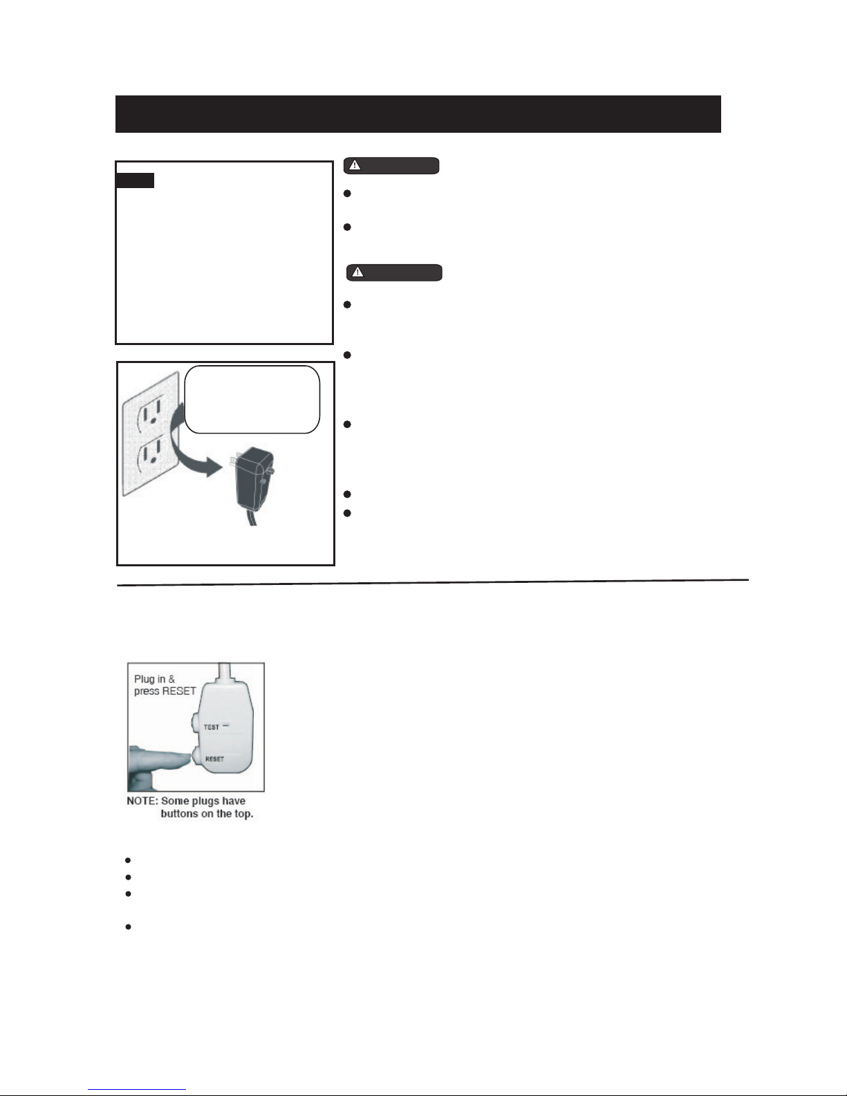
The power supply cord contains a current device that senses damage to the power cord. To test your power
supply cord do the following:
1. Plug in the Air Conditioner.
2. The power supply cord will have TWO buttons on the plug head.
Press the TEST button, you will notice a click as the RESET
button pops out.
3. Press the RESET button, again you will notice a click as the button
engages.
4. The power supply cord is now supplying electricity to the unit.
(On some products this it also indicated by a light on the plug head.)
Do not use this device to turn the unit on or off.
Always make sure the RESET button is pushed in for correct operation.
The power supply must be replaced if it fails reset when either the TEST button is pushed, or it cannot be
reset. A new one can be obtained from the product manufacturer.
If power supply cord is damaged, it cannot be repaired. It MUST be replaced by one
NOTES:
obtained from the
product manufacturer.
4

Temp/ Timer
Temp/ Timer
Energy
Saver
Sleep
Check
Filter
Fan
On
Time r
Off
High
Med
Dry
AutoAuto
On/Off
Low
Cool
Fan Speed
Mode
Temp/ Timer
Temp/ Timer
Energy
Saver
Sleep
Check
Filter
Fan
On
Time r
Off
High
Heat
Med
Dry
AutoAuto
On/Off
Low
Cool
Fan Speed
Mode
NORMAL SOUNDS
AIR CONDITIONER FEATURES
Sound of Rushing Air
At the front of the unit, you may
hear the sound of rushing air
being moved by the fan
High Pitched Chatter
High efficiency compressors
may have a high pitched chatter
during the cooling cycle.
Gurgle/Hiss
Gurgling or hissing noise may
be heard due to refrigerant
passing through evaporator
during normal operation.
Pinging or Switching
Droplets of water hitting condenser
during normal operation may cause
pinging or switching sounds.
Before you begin, thoroughly familiarize yourself with the control panel and remote as shown below
and all its functions, then follow the symbol for the functions you desire. The unit can be controlled
by the unit control alone or with the remote.
Vibration
Unit may vibrate and make noise
because of poor wall or window
construction or incorrect installation.
ELECTRONIC CONTROL OPERATING INSTRUCTIONS
UNIT CONTROL
5
(Cooling Only Models) (Electric Heating Models)

Temp/ Ti mer
Temp/ Ti mer
Sleep
Check
Filter
On
Time r
Off
High
Med
Auto
On/Off
Low
Fan Speed
Temp/ Ti mer
Temp/ Ti mer
Energy
Saver
Fan
On
Time r
Off
Dry
Auto
Cool
Mode
Temp/ Ti mer
Temp/ Ti mer
Sleep
Check
Filter
On
Time r
Off
High
Med
Auto
On/Off
Low
Fan Speed
AIR CONDITIONER FEATURES(CONTINUED)
TO TURN UNIT ON:
NOTE: The following instructions represent the Unit Controls, the same instructions can be used
for the Remote Control.
TO CHANGE TEMPERATURE
SETTING:
Press the On/Off button.
DO THIS:
Press to raise
DO THIS:
Press to lower
Press or hold either Up( ) or Down ( ) button
until the desired temperature is seen on the
display. This temperature will be automatically
maintained anywhere between 62 F(17 C) and
86 F(30 C). If you want the display to read
the actual room temperature, see To Operate
on Fan Only section.
NOTE:
TO ADJUST FAN SPEEDS:
Press to select
appropriate fan
speed
DO THIS: Used to select the Fan Speed in four steps-
Auto, Low, Med or High. Each time the button
is pressed, the fan speed mode is shifted.
NOTE:
6

Temp/ Ti mer
Temp/ Ti mer
Sleep
Check
Filter
Time r
Off
High
Med
Auto
On/Off
Low
Fan Speed
Temp/ Ti mer
Temp/ Ti mer
Energy
Saver
Fan
On
Time r
Dry
Auto
Cool
Mode
Temp/ Ti mer
Temp/ Ti mer
Energy
Saver
Fan
On
Time r
Off
Heat
Dry
Auto
Cool
Mode
AIR CONDITIONER FEATURES(CONTINUED)
TO SELECT THE
OPERATING MODE:
Press the Mode
button.
DO THIS:
To choose operating mode, press the Mode button.
Each time you press the button, a mode is selected
in a sequence that goes from Auto, Cool, Dry , Heat
(Cooling only models without) and Fan. The indicator
light beside will be illuminated and remained on
once the mode is selected.
NOTE:
To operate on Auto feature:
In this mode, the fan speed cannot be adjusted, it
starts automatically at a speed according to the
room temperature. If the room does not get too
warm, it will stay at Low speed.
To operate on Fan Only:
Use this function only when cooling is not desired,
such as for room air circulation or to exhaust stale
air(on some models). (Remember to open the vent
during this function, but keep it closed during
cooling for maximum cooling efficiency.) You can
choose any fan speed you prefer.
During this function, the display will show the actual
room temperature, not the set temperature as in the
cooling mode.
TO USE THE ENERGY
SAVER FEATURE:
Press the button
DO THIS:
In this mode, the fan will continue to run for 3 minutes
after the compressor shuts off. The fan then cycles
on for 2 minutes at 10 minute intervals until the room
temperature is above the set temperature, at which
time the compressor turns back on and cooling stars.
NOTE:
SLEEP FEATURE:
Press Sleep
button
DO THIS:
In this mode the selected temperature will increase by
1 C/2 F 30 minutes after the mode is selected.
The temperature will then increase by another
after an additional 30 minutes. This new
temperature will be maintained for 6 hours before it
returns to the originally selected temperature. This
ends the Sleep mode and the unit will continue to
operate as originally programmed. The Sleep mode
program can be cancelled at any time during operation
by again pressing the Sleep button.
O O
1 C/2 F
O O
NOTE:
7
To operate on Dry mode:
In this mode, the air conditioner will generally
operate in the form of a dehumidifier. Since the
conditioned space is a closed or sealed area, some
degree of cooling will continue.

Temp/Time r
Temp/Time r
Slee p
Chec k
Filt er
On
Timer
Off
High
Med
Auto
On/O ff
Low
Fan Sp ee d
Temp/Time r
Temp/Time r
Ener gy
Save r
Fan
On
Timer
Off
Dry
Auto
Cool
Mode
TIMER: AUTO START/
STOP FEATURE:
Press Timer
button
DO THIS:
AIR CONDITIONER FEATURES(CONTINUED)
First press the Timer button, the indicator light
besides word On illuminates. It indicates the Auto
Start program is initiated.
Press or hold the Up( ) or Down( ) to change
the Auto time by 0.5 hour increments, up to 10 hours,
then at 1 hour increments up to 24 hours. The control
will count down the time remaining until start.
The selected time will register in 5 second and the
system will automatically revert back to display the
previous temperature setting.
Turning the unit ON or OFF at any time will cancel
the Auto Start/Stop function.
NOTE:
CHECK FILTER FEATURE:
Press Check
Filter button
DO THIS: This feature is a reminder to clean the Air Filter for
more efficient operation. The LED(light) will illumi-
nate after 250 hours of operation. To reset after
cleaning the filter, press the Check Filter button and
the light will go off.
NOTE:
8

ADDITIONAL THINGS YOU SHOULD KNOW
Now that you have mastered the operating procedure, here are more features in your control that
you should become familiar with.
The Cool circuit has an automatic 3 minute time delayed start if the unit is turned off and on
quickly. This prevents overheating of the compressor and possible circuit breaker tripping.
The fan will continue to run during this time.
The control will maintain any set temperature within 2 F, between 60 F and 90 F degrees.
The control is capable of displaying temperature in degrees Fahrenheit or degrees Celsius.
To convert from one to the other, press and hold the Up and Down Temp/Timer buttons at the
same time, for 3 seconds.
9
Air Directional Louvers
The 4-way air directional louvers allow you to
direct the air flow Up or Down and Left or Right
throughout the room as needed. To adjust the
air directional louvers side-to -side, use the
center handles as you move it side-to-side.
Air Direction(4- way)
INSTALLATION INSTRUCTIONS
Do This First
(for existing sleeve)
Note that the air conditioner dimensions are: 24 inches wide, 14 / inches high, and 18 / inches
deep(without front). Install Air Conditioner according to these installation instructions to achieve
the best performance. Save these installation instructions for future reference.
1212
Items in Kit
You may not need all parts in the kit. Discard unused parts.
Hardware
2
2
3
Tapered Spacer Blocks (17 ` Long)
Plastic Divider ( )
4
Stuffer Seal ( )
4
1
2
3
4
5 seal ( )
1
62
7 3
8
No. Qty.
2
9
Centering/Support Blocks ( `)
4`x 3 `x 1
1
2
1
2
1
2
`x 4 `x 14 `
1
8
1
2
1
2
1`x 1 `x 84`
1
2
1`x 1 `x 25`
1
2
seal ( )
1`x 1 `x 14`
1
2
seal ( )
1`x 3/8`x 25`
seal ( )
1`x 3/8`x 14`
seal ( )
1`x 3/4`x 14`2
Hardware
2
1
1
Ground Wire (green)
2
Toothed washer for grounding screw
13
10
11
12
14 Grounding Screw
2
15 1
16 1
17
No. Qty.
4
18
Trim Frame (top & bottom legs)
Grille (plastic)
Grille Aluminum
Nuts (plastic)
Screw w/washer 4
Trim Frame (side legs)

INSTALLATION INSTRUCTIONS(CONTINUED)
10
How to Install
1. Identify the wall-sleeve brand for your installation, from the chart below.
NOTE: All wall sleeves used to mount the new Air Conditioner must be in sound structural condition
and have a rear grille that securely attaches to sleeve, or rear flange that serves as a stop for the Air
Conditioner.
CAUTION:
RUBBER
CLAMP
When installation is complete,
replacement unit MUST have a rearward
slope as shown. And ensure the
on the chassis at the back of the
unit had been removed before place the
unit into the sleeve. But if the rearward
slope is more than 1 2 , do not remove
the Rubber Clamp before installation.
REAR
LEVEL
FRONT
UNIT
Wall
Sleeve
1
/4 to 5
/16
2. Remove old Air Conditioner from wall sleeve and prepare wall sleeve as follows:
--- Clean interior (do not disturb seals).
--- Wall sleeve must be securely fastened in wall before installing Air Conditioner.
Drive more nails or screws through sleeve, into wall, if needed.
--- Repair paint if needed.
3. If not existing, drill a 3/16 clearance hole for
grounding screw through left side of wall sleeve,
in a clear area about 3 inches maximum (to suit)
back from front edge of sleeve as shown below.
Next attach ground wire inside sleeve, using
grounding screw and nut. Pull loose end of ground
wire out front of sleeve, and temporarily bend it
down and around lower edge of sleeve.
Wall sleeve to unit
sleeve grounding
1
3
Max.
3/16
Hole
4. Prepare the wall sleeve for installation of the new unit per the following Brand instructions.
5. Install new unit into wall sleeve.
6. To attach ground wire to the new unit, remove the screw from the left side front.
7. Assemble and install the Trim Frame (see instruction).
/
RUBBER
CLAMP
Brand Wall Sleeve Dimensions
Width Height Depth
General Electric/Hotpoint 26 15581578
Sears/Kenmore 2534167818 58
Carrier (51S Series) 1858
1678
2534
Friedrich 1634
1634
27
Emerson/Fedders 15
1534
2634
Whirlpool 257816 121718or 23
Fedders/Emerson 27 163416 341934
or
White-Westinghouse 2512151416, 17 or 22
12
Frigidaire 2512151416, 17 or 22
12
Carrier (52F Series) 2512151416, 17 or 22
12
#1 Emerson
#2 Fedders
#3 Fedders or Friedrich
#4 General Electric/Hotpoint
#5 Sears or Carrier(51S Series)
15 Deep
19 Deep
16 Deep
16 Deep
18 Deep
34
34
78
58
#6 Whirlpool
#7 Whirlpool
#8 White-Westinghouse/Frigidaire/
Carrier(52F Series)
#9 White-Westinghouse/Frigidaire
17 Deep
23 Deep
16 + 17 Deep
22 Deep
18
12

11
This units increased performance characteristics meant;
1. The rear air intake moved to the opposite side,
2. The depth had to be increased.
It is very important that these installation instructions are followed so your unit can operate at
maximum efficiency.
If this is an existing sleeve, and there is an existing rear grille, the louvers will have to be bent
as per the instructions at the beginning of each section.
If this proves too difficult to accomplish;
1. Remove the existing grille.
2. Place the included aluminum grille towards the rear of the unit.
3. Mark through the hole positions.
4. Drill through the sleeves flanges with a 1/8 drill bit.
5. Attached the new grille with self-threading screws and washers(not included).
6. It is VERY IMPORTANT that the grill e is placed exactly as shown below.
EITHER

12
Wall Sleeve Brands:
#1 Emerson 15 Deep
1. Redirect the louvers at the back of the wall
sleeve as shown in the illustration. The use
of pliers is recommended.
2. Attach(1)1 x3/8 x25 long seal in the center at
the top of the sleeve. Remove the backing paper
and press into position.
3. Attach the (2) 1 x3/8 x14 long seals to the
left and right sides of the sleeve.
4. Cut (2) 1 x3/8 x25 long seal to 14 long, and
attach it to the vertical sections of the rear grille
as shown.
5. Attach (2)4 x3 x1 centering/support blocks
one on each side wall. Place in center of side
wall with the tapered end facing the opening.
6. Gently slide unit into sleeve.
7. Before sliding all-the-way back, remove 2nd
screw from front on left side of unit.
8. Remove the plastic washer from the screw.
9. Screw and attach the other end of the ground
wire to the unit as shown in picture. Make sure
that the toothed washer is against the cabinet.
10.Slide the unit completely to the rear to ensure
a good seal, making sure the ground wire does
not become tangled.
11.Seal & Frame the unit as described on the last
page of these instructions.
1
/21
/21
/2
2

13
Wall Sleeve Brands:
#2 Fedders 19 Deep
1. Redirect the louvers at the back of the wall
sleeve as shown in the illustration. The use
of pliers is recommended.
34
/
2. Attach(2)4 x3 x1 centering/support blocks
one on each side wall. Place in center of side
wall with the tapered end facing the opening.
3. Cut (2) 17 Tapered Spacer Blocks as shown
below into two pieces.
4. The 4 section is placed in front of the rib on
base with the tapered end facing the back of
the sleeve. The remaining portion will be
placed behind the rib again sloping toward
the rear of the sleeve. This helps induce a
rearward slope on the unit.
5. Attach (1)1 x3/8 x25 long seal in the center
at the top of the sleeve. Remove the backing
paper and press into position.
6. Attach (2) 1 x3/8 x14 seals to the left and
right sides of the sleeve.
7. Cut (2) 1 x3/8 x25 long seal to 14 long
and attach it to the vertical sections of the rear
grille as shown.
8. Gently slide unit into sleeve.
9. Before sliding all-the-way back, remove 2nd
screw from front on left side of unit.
10. Remove the plastic washer from the screw.
11. Screw and attach the other end of the ground
wire to the unit as shown in picture. Make sure
that the toothed washer is against the cabinet.
12.Slide the unit completely to the rear to ensure
a good seal, making sure the ground wire does
not become tangled.
13.Seal & Frame the unit as described on the last
page of these instructions.
1
/21
/2
/2
1
/2
/2
Cut Here
3/4
17
Tapered Spacer Block 1
Protection Paper
Backing
5
4

14
Wall Sleeve Brands:
#3 Fedders or Friedrich 16 Deep
1. Redirect the louvers at the back of the wall
sleeve as shown in the illustration. The use
of pliers is recommended.
34
/
2. Attach(2)4 x3 x1 centering/support blocks
one on each side wall. Place in center of side
wall with the tapered end facing the opening.
3. Cut (2) 17 Tapered Spacer Blocks as shown
below into three pieces.
4. The 2 section is placed in front of the rib on
base with the tapered end facing the back of
the sleeve. Cut the remaining portion to 12
and placed behind the rib again sloping toward
the rear of the sleeve. This helps induce a
rearward slope on the unit.
5. Attach (1)1 x3/8 x25 long seal in the center
at the top of the sleeve. Remove the backing
paper and press into position.
6. Attach (2) 1 x3/8 x14 seals to the left and
right sides of the sleeve.
7. Cut (2) 1 x3/8 x25 long seal to 14 long
and attach it to the vertical sections of the rear
grille as shown.
8. Gently slide unit into sleeve.
9. Before sliding all-the-way back, remove 2nd
screw from front on left side of unit.
10. Remove the plastic washer from the screw.
11. Screw and attach the other end of the ground
wire to the unit as shown in picture. Make sure
that the toothed washer is against the cabinet.
12.Slide the unit completely to the rear to ensure
a good seal, making sure the ground wire does
not become tangled.
13.Seal & Frame the unit as described on the last
page of these instructions.
1
/21
/2
/2
1
/2
/2
Cut Here
3/4
17
Tapered Spacer Block 1
Protection Paper
Backing
12-1/2 2-1/2
1
/2
1
/2
5

15
Wall Sleeve Brands:
#4 General Electra/Hotpoint 16 Deep
1. Redirect the louvers at the back of the wall
sleeve as shown in the illustration. The use
of pliers is recommended.
78
/
2. Cut (2) 17 Tapered Spacer Blocks as shown
below into two pieces.
3. Install as shown with the tapered end from
the back of the sleeve. This helps induce a
rearward slop on the unit.
4. Attach (1)1 x3/8 x25 long seal in the center
at the top of the sleeve. Remove the backing
paper and press into position.
5. Attach (2) 1 x3/8 x14 seals to the left and
right sides of the sleeve.
6. Cut (2) 1 x3/8 x25 long seal to 14 long
and attach it to the vertical sections of the rear
grille as shown.
7. Center unit and gently slide unit into sleeve.
8. Before sliding all-the-way back, remove 2nd
screw from front on left side of unit.
9. Remove the plastic washer from the screw.
10. Screw and attach the other end of the ground
wire to the unit as shown in picture. Make sure
that the toothed washer is against the cabinet.
11.Slide the unit completely to the rear to ensure
a good seal, making sure the ground wire does
not become tangled.
12.Seal & Frame the unit as described on the last
page of these instructions.
1
/2
3/4
17
Tapered Spacer Block 1
Protection Paper
Backing
Cut Here
13
5
4

16
Wall Sleeve Brands:
#5 Sears or Carrier 51S Series
( 18 Deep)
1. Redirect the louvers at the back of the wall
sleeve as shown in the illustration. The use
of pliers is recommended.
58
/
2. Install (2) tapered spacer blocks to the floor of
the sleeve as shown. DO NOT CUT THERE
BLOCKS. This helps induce a rearward slop
on the unit.
3. Install as shown with the tapered end from
the back of the sleeve. This helps induce a
rearward slop on the unit.
4. Attach (1)1 x3/8 x25 long seal in the center
at the top of the sleeve. Remove the backing
paper and press into position.
5. Attach (2) 1 x3/8 x14 seals to the left and
right sides of the sleeve.
6. Cut (2) 1 x3/8 x25 long seal to 14 long
and attach it to the vertical sections of the rear
grille as shown.
7. Center unit and gently slide unit into sleeve.
8. Before sliding all-the-way back, remove 2nd
screw from front on left side of unit.
9. Remove the plastic washer from the screw.
10. Screw and attach the other end of the ground
wire to the unit as shown in picture. Make sure
that the toothed washer is against the cabinet.
11.Slide the unit completely to the rear to ensure
a good seal, making sure the ground wire does
not become tangled.
12.Seal & Frame the unit as described on the last
page of these instructions.
1
/2
5
4

17
Wall Sleeve Brands:
#6 Whirlpool 17 Deep
1. Redirect the louvers at the back of the wall
sleeve as shown in the illustration. The use
of pliers is recommended.
18
/
2. Cut (2) 17 Tapered Spacer Blocks as shown
below into two pieces.
3. Install to the floor of the sleeve as shown.
This helps induce a rearward slop on the
unit.
4. Attach (1)1 x3/8 x25 long seal in the center
at the top of the sleeve. Remove the backing
paper and press into position.
5. Attach (2) 1 x3/8 x14 seals to the left and
right sides of the sleeve.
6. Cut (2) 1 x3/8 x25 long seal to 14 long
and attach it to the vertical sections of the rear
grille as shown.
7. Center unit and gently slide unit into sleeve.
8. Before sliding all-the-way back, remove 2nd
screw from front on left side of unit.
9. Remove the plastic washer from the screw.
10. Screw and attach the other end of the ground
wire to the unit as shown in picture. Make sure
that the toothed washer is against the cabinet.
11.Slide the unit completely to the rear to ensure
a good seal, making sure the ground wire does
not become tangled.
12.Seal & Frame the unit as described on the last
page of these instructions.
3/4
17
Tapered Spacer Block 1
Protection Paper
Backing
Cut Here
13
5
4

Wall Sleeve Brands:
#7 Whirlpool ( 23 Deep)
1. Redirect the louvers at the back of the wall
sleeve as shown in the illustration. The use
of pliers is recommended.
1. Place (2) 1 x1 x14 seals against each side.
2. Gently slide unit in and check if amount extend-
ing from the sleeve is sufficient once the trim
frame is attached.
3. If position is Ok, remove unit and proceed to
the next step. If not go to step 8.
4. Attach (1)1 x1 x25 long seal in the center
at the top of the sleeve. Remove the backing
paper and press into position.
5. Attach (2) 1 x1 x14 seals to the left and
right sides of the sleeve.
6. Cut (2) 1 x1 x25 long seal to 14 long
and attach to
.
7. Attach the tapered spacer blocks to the floor of
the sleeve. Now go to step 14.
8. Attach 1 x x14 long seal over the solid
vertical portion of the rear grille.
9. Attach (2) 4 x3 x1 foam blocks with the
slot overlapping the seal above.
10. Install the divider into the slots of the foam
blocks. You may need to trim the length to size.
11. Repeat steps 8-10 for the other vertical shown
portion of the grille as shown in the picture.
12. Attach (2) 1 x1 x14 seals along the sides
of the sleeve again making sure all seals are
flush.
13.
14. Center unit and gently slide unit into sleeve.
15. Before sliding all-the-way back, remove 1st
screw from front on left side of unit.
16. Remove the plastic washer from the screw.
17. Screw and attach the other end of the ground
wire to the unit as shown in picture. Make sure
that the toothed washer is against the cabinet.
18.Slide the unit completely to the rear to ensure
a good seal, making sure the ground wire does
not become tangled.
19.Seal & Frame the unit as described on the last
page of these instructions.
the vertical sections of the grille as
shown
Cut the 1 x1 x25 seal to fit the top of the
sleeve. The pieces must be fitted flush to the
edge of the divider.
Use these next steps if the unit requires extra
extension into the room.
Because of the increased unit depth, first try
dry fitting using the method described below:
1
/2
1
/2
1
/2
1
/2
3
/4
1
/21
/21
/2
1
/2
18
5
4
11
8
10
12
9
13
1
/2
Table of contents