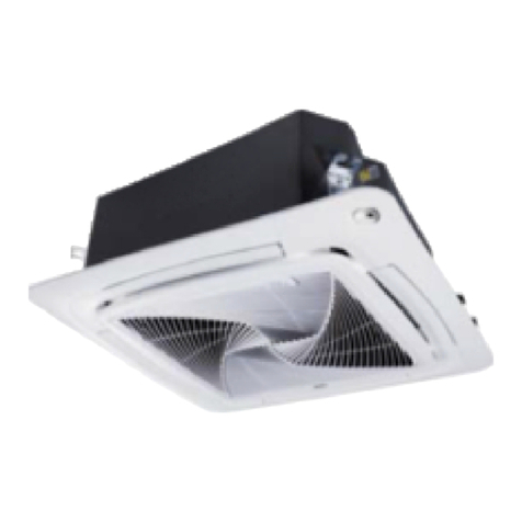
Airwell DVHA-280N-01M22 Guide

IMPORTANT NOTE:
Read this manual carefully before installing or operating your new air conditioning unit. Make sure to
save this manual for future reference.
22.AW.DVHA.072-096.R410A.UM+IM.EN.FR.DE.IT.SP.PO.01.21.Rev01
User & installation manual
DUC
TED UNIT (HIGH ESP 100~196Pa)
R410A
Multilingual Manual
(English
-
French - German -
Italiano -
Portugues
- Español
)

User & Installation Manual
IMPORTANT NOTE:
Read this manual carefully before installing or operating your new air conditioning unit. Make sure to
save this manual for future reference.
22.AW.DVHA.072-096.R410A.UM+IM.EN.FR.DE.IT.SP.PO.01.21.Rev01
DUCTED UNIT (HIGH ESP 100~196Pa)
R410A
English Manual
DVHA-280/220N-01M22

Contents
If the supply cord isdamaged, it must be
replacedbythemanufacturer,itsserviceagent
orsimilarlyqualified personsinorderto avoid
a hazard.
Thisappliance isnot intended foruse by
persons(including children)with reduced
physical,sensoryormentalcapabilities,orlack
ofexperienceandknowledge,unlesstheyhave
been givensupervisionorinstruction
concerninguse of the appliance bya person
responsible fortheirsafety.
Childrenshould be supervisedto ensure
that theydo not playwith the appliance.
Thisappliancecanbe used bychildren aged
from 8 yearsandabove and personswith
reduced physical, sensoryormental
capabilitiesorlackof experienceand
knowledgeiftheyhavebeengivensupervision
orinstructionconcerninguseoftheappliance
ina safe wayandunderstand thehazards
involved. Children shallnot playwith the
appliance. Cleaning and usermaintenance
shallnot be made bychildren without
supervision.
Theappliancesarenotintendedtobeoperated
bymeansof an externaltimerorseparate
remote-controlsystem.
Keeptheapplianceanditscordoutofreach
of children lessthan 8years.
Warning
Yourair conditioner maybesubjecttoany
change owing totheimprovementof
Airwell products.
VRF series multipleairconditioning systems
adopt the consistent runningmode,by
which, allindoor unitscanonlybeheating
or refrigerating operation at the same time.
Toprotect thecompressor, theair
conditioningunitshouldbe poweredonfor
over 12hours before usingit.
All indoorunitsof the samerefrigerating
systemshould use theunified powerswitch
toensure that allindoor unitsareinthe
stateofbeingpoweredonatthesametime
duringtheoperationofair conditioner.
UserManual
PartsandFunctions 1
Safety 2
6
Fault Checkup
7
InstallationProcedures
14
ElectricalWiring
20
TestRun&Fault Code
5
Maintenance
ProductFeatures
1.Functionof central control
(optional fromourcompany);
2.Automaticdisplayof fault detection;
3.Theairconditionerisprovidedwiththe
functionfocompensation forpowersupply.
During operation,whenthe powersupply
fails emergentlyand resumes again,theair
conditionerreturns totheworkingcondition
beforepowerfailure,if providedwith
compensationfunction.
4.Nowthisindoorunit onlyhaswired
controllerfunction,theindoorunit that has
remotecontrollerfunctionneedtosetin
factoryespecially.
cooling
dry
heating
indoor
outdoor
indoor
outdoor
max.
min.
max.
min.
max.
min.
max.
min.
DB: 32
WB: 15
DB: 18
DB: 43
DB: -5
DB: 27
DB: 15
DB: 21
DB: -15
WB: 23
WB: 14
WB: 26
Operating Range of Air Conditioner
21
Moveandscrap theairconditioning

1
Partsand Functions
indoorunit
airoutlet port
airinlet port
flue
flue
Condensated waterpan

2
Safety
If theairconditioneristransferredto a new user, thismanualshallbetransferred to the user,
togetherwith the conditioner.
Before installation, be sure to readSafetyConsiderationsin thismanualforproperinstallation.
Thesafetyconsiderationsstated below isdividedinto Warning”and Attention”.The
matterson severeaccidentscaused fromwrong installation, which islikelytolead to death or
seriousinjury, are listed in Warning”. However, the matterslisted in Attention”are also
likelycause thesevere accidents. In general, bothof them are the important itemsrelated to
the security, whichshouldbe strictlyabided by.
Afterthe installation, perform test run to makesure everything isin normalconditions,andthen
operate and maintain theairconditionerinaccordance with the UserManual.The UserManual
should be deliveredto theuserforproperkeeping.
!Warning
! !
! !
Pleaseaskthespecialmaintenance station forinstallation and repair. Waterleakage, electric
shocks orfireaccidentsmight be caused from improperinstallation ifyouconduct the installation
byyourown.
The installation should beconducted properlyaccording tothis manual.Waterleakage, electric
shocksorfireaccidentsmight be caused fromimproperinstallation.
Pleasemake sure to installthe airconditioneronthe place where can bearthe weight of the
airconditioner.The airconditionercan’t beinstalled on the gridssuch asthenon-specialmetal
burglar-proof net. The place with insufficient support strengthmight cause thedropdown of the
machine, which maylead to personalinjuries.
Theinstallation should beensured against typhoonsand earthquakes, etc.Theinstallation
unconformableto therequirementswilllead to accidentsdueto theturnoverof themachine.
Specificcablesshould beused forreliable connectionsof the wirings. Pleasefixthe terminal
connectionsreliablyto avoid theoutside forceapplied onthe cablesfrom being impressedon
the cables. Improperconnectionsand fixingsmight leadto suchaccidentsasheatingorfire
accidents.
Correctshapesof wiringsshouldbe kept while the embossed shape is not allowed. The wirings
should be reliablyconnected toavoidthe coverandthe plateof theelectricalcabinet lipping
the wiring. Improperinstallation might causesuch accidentsasheating orfire accidents.
While placingorreinstalling the airconditioner,exceptthe specificrefrigerant (R410A),don’t
let theairgo into therefrigerationcycle system. The airin the refrigerationcycle system might
lead to the cracking orpersonalinjuriesdue to abnormalhighpressure of therefrigerationcycle
system.
During installation, pleaseusethe accompanied spare partsorspecificparts. If not, water
leakage, electricshocks, fireaccidentsorrefrigerant leakagemight becaused.
Don’tdrain the waterfrom the drainpipeto the waterspout where mayexistharmfulgasessuch
assulfureted gasto avoidthe harmfulgasesentering intothe room.
During installation, if refrigerant leakageoccurs, ventilation measuresshouldbe taken, forthe
refrigerant gasmight generate harmfulgasesupon contacting theflame.
Afterinstallation, checkifanyrefrigerant leakage exists. Ifthe refrigerant gasleaksinthe room,
such thingsasairblowing heatersandstoves, etc. maygenerateharmfulgases.

3
Safety
Don’tinstallthe airconditionerat the placeswhere the flammable gasesmayleak. In casethe
gasleakage occursaround themachine, such accidentsasfiredisastersmaybe caused.
Thedrainpipe should be properly mounted according to thismanualasto ensure the smooth
drainage. In addition, heat preservation shouldbe taken to avoidcondensation. Improperdrainpipe
mountingmight cause waterleakage, whichwillget the articlesat home wet.
Therefrigerantgaspipeandliquidpipeshouldbe heatinsulatedtopreserveheat.Forinappropriate
heat insulation, the watercausedfrom the condensationwill drop to get thearticle at home wet.
!Attention
Theairconditionershouldbe effectivelygrounded. Electricshocksmayoccurifthe airconditioner
isungrounded orinappropriatelygrounded. The wire forearthingshouldn’t be connected to the
connectionsonthe gaspipe, waterpipe, lightningrod ortelephone.
The breakerforelectricityleakage shouldbemounted. If not, accidentssuchaselectricshocks
mayhappen.
Theinstalled airconditionershouldbe checked forelectricityleakage bybeingpowered.
If theambienthumiditybiggerthan80%, when thewaterdischargehole beblocked orthe filter
becomesdirty, orairflow speedchange, there maybe leadsto condensingwaterdropdown,
and at the same timethere maybe some dropsof waterspit out.

4
Safety
!Attention
Payattention to the
aeration condition
to avoid anoxic
symptom.
It isnot allowed to put anyheating
apparatusunderthe indoorunits,forthe
heat maycausedistortion of theunits.
Flammableapparatusshouldnot beplaced
inthe place where the airconditionerwind
could reachdirectly, orincomplete burning
of theapparatus
maybe caused.
3-minute protection
Toprotect the unit, compressorcan be
actuated with atleast 3-minute delayafter
stopping.
Close the window to avoid outdoorair
gettingin.
Curtainsorwindow
shutterscan be put
down to avoid the
sunshine.
Do not put flammable spraycloseto the air
conditioner.
Don’t inject flammablespraytowardsthe
airconditioner, which may
cause fire.
Stopping fan rotation
Theunit which stopsoperating willactuate
the fan fora 2-8 min swing every30-60
minutesforprotecting the unit while other
indoorunit arein the operating state.
Powershould be cut off when theair
conditioneris left unused fora long period.
Powerwill be consumed if the air
conditioneris not powered off. The power
switch of the outdoorunit switch should be
powered on 12 hoursin advance before
operation to protect the unitaftera long
period ofstorage.
Defrosting during heating
To improve the heating effect, the outdoor
unit willperformdefrosting automatically
when frost appearson the outdoorunit
during heating (approximately2-10 min).
During defrosting, the fan of the indoorunit
runsata low speed orstopswhile thatof
the outdoorunit stopsrunning.
Do not use waterheaterorlike next to the
indoorunit and the wired controller.
Water/powerleakage orshort circuit may
happen if the steamgenerating apparatus
isworking nextto machine.
Use the fuse with propercapacity.
Metalwiresand copperwires, etc.,
maycause fire orotherfaults.
It cannot be used forthe preservation of
food, living creature, precise instrument
and artworks, etc, otherwise damage
mayoccur.
Plantsand animalsshould not be put to
the placewhere wind of the airconditioner
blowsdirectly, otherwise damage to
themmaybe caused.
Checkthe mount table
of theairconditionerfordamage fora long
period ofoperation.
If placed on the damaged table, the
unit maydrop down causing damage.
Thisappliance isnotintended foruse by
persons(including children)with
reducedphysical, sensoryormental
capabilities, orlackofexperience and
knowledge, unlesstheyhave been given
supervision orinstruction concerning use
of the appliance bya person responsible
fortheirsafety.
Cleaning the unit with watermaycause
electricshock.
Do not touch the switch withthe wet
hand to avoid powershock.
Stop running and switch off the manual
powerswitch when cleaning the
unit.
During the operation of the controlunit,
don’t switch off the manualpowerswitch
and the controllercan be used. Please do
not pressthe liquid crystalzone of
controllerto prevent damage

5
Maintenance
Onlywhen the aircleanerisswitched offand disconnectedto the powersupply canitbe cleaned,
orelectricshockand injurymayappear.
Maintenance before and afterOperating Season
BeforeOperatingSeason:
1.Pleasemake the following checkup. If abnormalcondition occurs,consult the after-service
personnel.
There isnoblockagein inlet port and outlet port of outdoorand indoorunits.
The ground lineand the wiring areinthe properstate
2. Aftercleaning, the aircleanermust be mounted.
3. Switchon tothe power.
AfterOperating Season:
1. In sunnydays, blowing operation can beperformed forhalf adayto make the inside of
machine dry.
2. Electricalpowershould becut down toeconomize electricity, orthe machine willstill
consume power.Aircleanerand shellmust be mountedaftercleaning.
CleaningAirCleaner:
Don’t rinse the aircleanerwith hotwaterof above 50℃toavoid fading and distorting.
Don’t put theaircleaneron the fire to dryto avoid catching fire.
Attention
Wipedust with waterordustcollector.
(A)Wipedust withdust collector. (B)Cleanitwith soft bushinmilddetergent
if there istoomuch dust on it
Throwoffthewaterandairing
it inthe cooldrycondition.
CleaningWind Deflector:
Donot wipe the wind deflectorwith waterforciblyto avoid fallingoff.
Cleaningthe airoutlet port and the shell:
Don’t usegasoline, benzene, diluents, polishing powderorliquid insecticideto clean them.
Donot clean them with hot waterof above 50 to avoid fadingordistorting.
Attention
Wipethemwithsoftdrycloth.
Waterorneutraldrycleanserisrecommended if the dust cannot be removed.
TheWind Deflectorcan bedismantled to clean (asbelow).

6
Fault Checkup
Waterflow sound
Cracking sound
Terriblesmellin
outlet air
Flashing operating
indicator
Awaitingindication
Sound in
shutdown indoor
unit orwhite
steam orcold air
Clicking sound
when switching the
aircondition on
Start orstop working
automatically
Failure towork
Badcooling&
heatingeffects
Symptoms Reasons
Waterflow soundcan be heard when starting operation, during
operation orimmediatelyafterstopping operation. Whenit starts
to workfor2-3minutes, the sound maybecome louder, which is
the flowing sound ofrefrigerantorthe draining sound of condensed
water.
Duringoperation,the airconditionermaymakethecracking
sound, whichiscaused from the temperaturechangesorthe
slight dilation of heat exchanger.
The terriblesmell,causedfrom walls,carpet, furniture,clothing,
cigarette and cosmetics, attachesonthe conditioner.
Whenswitching itonagainafterpowerfailure,turnonthe manual
powerswitch andthe operating indicatorflashes.
Itdisplaystheawaitingindicationasitfailsto performrefrigerating
operation while otherindoorunitsare inheating operation. When
the operatorset itto the refrigerating orheating mode andthe
operation isoppositeto the setting, itdisplaysthe awaiting indication.
To prevent oiland refrigerant from blocking the shutdown indoor
units,refrigerantflowsinthe shorttime and makethesounds
ofrefrigerantflowing.Otherwise,whenotherindoorunitsperforms
heatingoperation, white steammayoccur;duringrefrigerating
operation, coldairmayappear.
When the conditioneris powered on, the soundismadedue
to the resetting of the expansion valve.
Checkif it isin thestateof Timer-ON andTimer-OFF.
Checkif there isa powerfailure.
Checkif the manualpowerswitchisturnedoff.
Checkif the supplyfuseandbreakerare disconnected.
Checkif the protectiveunit isworking.
Check ifrefrigerating and heating functionsareselected
simultaneouslywith the awaiting indicationon linecontrol.
Checkifairintakeportand airoutlet portofoutdoorunitsare
blocked.
Checkif the doorand windowsare open.
Check ifthefilteringscreenofaircleanerisblockedwithsludge
ordust.
Checkif the setting of windquantityisat low wind.
Checkif the setting of operation isat the Fan Operation state.
Checkif the temperaturesettingisproper.
When otherabnormalconditionsoccur.
Underthe following circumstances, immediately stop the operation, disconnect themanualsupply
switchand contact the after-servicepersonnel.
When buttonsare inflexibleactuated;
When itcannot stillbe operated afterremoving theoperationof protectiveunit;
When fuse and breakerhavebeenburnt overand over;
When thereare foreign objectsandwaterin therefrigerator;
Pleasecheck thefollowingwhenconsigningrepairservice:

7
InstallationProcedures
The standardattachedaccessoriesof theunitsof thisseriesrefertothe packing; prepare other
accessoriesaccording tothe requirementsof the localinstallation point of ourcompany.
Thereare two setsof pipesin theunit,pleaseusebranchpipewhen installation,the specis FQG-
B370,detailsplsasereferto theusingguide of the Branchpipe.
1. Before installation[beforefinishingtheinstallation,don tthrow away the attachedparts
requiredforthe installation]
Determine theroute tomove theunit to the installation site;
Don’t tearthe package open before moving theunit to the installation site. Whenunpacking is
needed, asoft materialorprotectorblockwithropescanbe usedto lift the unitto avoiddamaging
orscrapingof theunit.
2.Selecttheinstallation site
(1)The installation siteshould be selected according thefollowing conditions, whichshould be
approved byusers.
where an idealairdistributioncanbe ensured;
where there isnoblockagein the airpassage;
where the condensed watercan be drainedout properly;
where the strength canbearthe weight of the indoorunit;
where enough space can beensured formaintenance.The outside airshouldbe input from
the outdoordirectly from the blastpipe.If theblastpipecan’tbe jointed,the aircan’tbe input from
the suspended ceiling.
wherethelengthsof the piping between indoorunitsand outdoorunitsarewithinthe allowable
range (refertoInstallation of OutdoorUnits)
where the distanceof at least 1mbetween indoorunits,outdoorunits,mainssupply, connecting
wiresand television orradio shouldbe kept astoavoid the imagedisturbanceandnoisesof the
above electricalappliances. (Even if 1mcanbe ensured, noise might occurif there isstrong
electricwave.)Additionally, equipments, televisionorothervaluablescan’tbe put underthe unit
astoavoidthe condensed waterof theunitfrom dropping into the abovearticles,causing damaging.
(2)Height of Ceiling:The ceilingshould belocatedat theplace, where the centralposition
of airoutlet port islessthan 3mhigh abovethe ground.
(3)Hoistingstudsshouldbe usedduring installation. Checkif the locationcan bearthe weight
of the unit. Reinforceit before installation if necessary.
360 1610
1525
1510
upside Ceiling
(2)Locationrelationbetween inspectionhole onthe ceiling
and the unit and the hoisting studs(unit: mm).
3.Preparation before Installation
(1)Please referto thecooling systemdiagram of the unit
before installation,and connectthe pipesaccordingto the
diagram.
over100 over900
air inlet port
airoutletport
indoorheat exchanger
gaspipe
tiein
liquidpipe
tiein
liquid
segregator Mfan
environmental
temperature
electrical
expandtion
filter
electrical
expandtion
filter
TC1
TC2

8
InstallationProcedures
0~5mm
100 196
StandardStaticPressure Max. StaticPressure
StaticPressureRange
unit: Pa
NB:
Whenthe sizesofthe mainunitdon’tmatchthe holeonthe ceiling, regulate theslot onthe hanging
bracket.
(a)Adjust the levelwith a levelmeteroraccording to the followingways:
(b)Unlessit isregulated to the levelposition, faultsorerrorsmight occurforthe floaterswitch.
Adjusting thelevel
Make theadjustment asshown inthe figure below.
(3)If necessary, make ahole forinstallation and inspectionon the ceiling. (used forthesituation
with aceiling)
Forthe size of the inspection hole on the ceiling, please refertothe above drawing.
Before installation, finishall thepreparationsforallpiping connectedto indoorunits(refrigerant,
waterdrainage)and wiring (connection line of theline control, connection line between indoor
unitsand outdoorunit)so that theycan be connected with indoorunitsright afterinstallation.
Forthe inspectionhole, theceiling might be reinforced to keep the evennessof the ceiling
and avoid the vibration of the ceiling. Fordetails, please consult the construction contractor.
notchgrapping
notchplug plug
concrete
hoisting studM10
(4)Installthe hoisting studs(M10 bolts)
In orderto support theweight of the unit, use barb
boltsinthesituationwithaceiling.In the situationwith
the new ceiling, useinlaid bolts, embedded boltsor
otherpartsprovided onsite. Before proceeding the
installation, adjust the gap between the bolt and the
ceiling.
M10nut hoistingstud
M10shim
M10 springwasher
mainunit
(5)Installation of IndoorUnits
Fix the indoorunitwiththe hoistingstud.
Ifnecessary, the machine can be hanged
on thebeam with boltsinsteadof the
hoisting stud.
onesideofpiping
water supply
level
PVC tube
makeonesideofpipingalittlelower

9
InstallationProcedures
4. Drainpipes
(a)Keep agradient (1/50-1/100)of thedrainpipesand avoid lobingorcurving.
washport
washport
main unit
drainage hose
joint(purchasedat local shop)
sealingwasher [for insulation]
(accessory)
hardPVC tube(purchased atlocalshop)
sealingwasher [for insulation]
(accessory)
sealing washer [forinsulation]
(accessory)
threadclip
(accessory)
drainagehose
binding
ensurethe biggestheightdifference
(about 100mm)
gradientof1/100 or over
Thehard PVC tube in the room must be provided with theheatinsulating layer.(e)
Whenthe laid drain piping isusedformultiple equipments,the publicpipingshouldbe lower
about 100mm thanthe washportsof equipments, asshownin thefigure.Thickerpipesshould
be used forthisapplication.
(d)
1.5m~2m
ProperPiping
hangingbolt
heat insultor
gradientof1/100 or over
ImproperPiping
air outlet port
avoidlobing
avoidcurving
don't putpipe
intowater
(c) Forthedrainpipe, the generalpurposehardPVC tube canbepurchased atlocalshops.During
the connection, insertthe end ofPVC tubeinto the washportand fasten itwith drainage hose
andthread clip. Bindingagentsshouldn’tbe used toconnectthewashport and drainage hose.
(b)When connecting the drainpipe to the equipment, don’t applytoo much force on oneside of
theequipment. Meanwhile, thepipingshould be positionedascloseto theequipment as
possible.

10
InstallationProcedures
(a)Provide about 1000ccof watertothe equipment via airoutlet port withthe feed pump.
(b)During refrigerating operation, checkthe drainage system.
Procedures
(a)Afterfinishing theelectricalsystem, test thedrainagesystem.
(b)During testing, make sure that the waterflow passesthepipingcorrectlywithout anywater
leakage at the connection.
(c) In thecondition of new house, test thedrainagesystem before fittingup the ceiling.
(d)Evenif it isinstalled in theseason neededto heating, the testing shouldalso be performed.
Testing Drainage System
5. Installation ofAirReturn& AirExhaustPipes
Forthe choiceand installation of
airreturn port, airreturn pipe, air
exhaustportand exhaustpipe,
please consult service personnel
of Airwell company. Calculate
the design chartandexterior
static pressure, and select the
exhaust pipe with appropriate
length and shapes.
mainunit of air
conditioner
ceiling
suface
specialexhaust
port (purchased at
localshop)
exhaustpipe
(purchased
atlocal
shop) inspection
hole
air return
pipe
(purchase
datlocal
shop)specialairreturn
pipe(purchasedat
localshop) withair
cleaner
Don’t placethe drainpipesat the placeswhere there isirritant gas. Don’t put thedrainpipe
directlyinto thesewer,where there might be gaseswithsulfur.
(g)
Watertrap:
Because itiseasytocauseminuspressure at the waterdrainagehole, once the waterlevel
in drainage pan goesup, waterwillleak.To prevent waterleakage, we design a watertrap
here.
Watertrap shouldbe easy to be cleaned.Adopt T-shape connectorlikebelow figure. Itshould
be nearthe unit,asthe figure,itissetat themiddleof drainage hose.
(f)
indoor
H1=100mm orfanmotorstaticpressure
H2=H1(oramong 50mm~100mm)
1
2

11
InstallationProcedures
6. Account ofsimplerectangleduct
Assumethe friction resistance perunitis1Pa/m, when the sizeof one sideof airpipe is25omm,
like below figure:
The length differencebetween pipesshould belimited
to be lessthan 2:1;
Make the pipingasshort aspossible;
Keepthe min. elbow quantity;
Windthe heatinsulatingmaterialaroundtheflange
betweenthe mainunitandthe exhaust pipe forheat
insulation and sealing. Install the piping beforefitting
up theceiling.
incorrect incorrect correct
flux gaspipe
(mmxmm)
1200m3/h
(20m3/min)
300m3/h
(5m3/min)
250x310
250x120
B
A
unit
withfilter
(purchased additionally)
staticpressurebox
A 300m3/h
B 300m3/h
A 1200m3/h
A 1200m3/h
simple duct selection Note:1Pa/m
flux item
shape squarepipe
m3/h(m3/min)
100
200
300
400
500
600(10)
800
1,000
1,200(20)
1,400
1,600
1,800(30)
2000
2400
3,000(50)
3,500
4,000
4,500
5,000
5,500
6,000(100)
250 x60
size
(mmxmm)
250 x90
250 x120
250 x140
250 x170
250 x190
250 x230
250 x270
250 x310
250 x350
250 x390
250 x430
250 x470
250 x560
250 x650
250 x740
250 x830
250 x920
250 x1000
250 x1090
250 x1180
straight pipe account as1Papermeter,
1Pa/m
bended section eachbendregardedas3-4m
of straight pipe
airoutlet section
staticpressure box
inlet grille(with filter)
account as25Pa
50Pa perstaticpressure box
40Pa foreachone
Account of resistancein duct:

12
InstallationProcedures
7. CautionsinInstallationof AirReturnPipe & ExhaustPipe
8.Examples forBadInstallation
It isrecommended tousethe blast pipes, which
canbe anti-condensationandabsorbsound.
(purchasedat localshops)
Completetheinstallationoftheblastpipesbefore
fitting upthe suspended ceiling.
Heatinsulation shouldbemadefortheblast
pipes.
The specialexhaustport should be arranged at
the place wherethe airisdistributedevenly.
Aninspection holeshouldbelefton thesurface
of the ceiling forfuture maintenance.
specialexhaust port
positioningwithbolt
blast pipe
air
air
Theunitis notequippedwith theairreturn pipeand the innerside of the suspendingceiling is
usedastheblastpipe,causingthehumidityincreasing duetoirregularairmass,strongwind
orsunlight from the outside world.
Theremightbecondensatedropping downatthe outersideoftheblastpipe.The humidityis
high,even ifthe innerside ofthe suspendedceilingisn’tused asablastpipein new concrete
buildings.Atthistime,the wholebodyshouldusethe thermo woolforheatpreservation(the
thermo woolcanbe packed with asteelwire).
It is operated underthe conditionsbeyond the limits, leading to the overload of thecompressor.
Affected bythe capacityof theexhaust fan, and the strong wind and wind direction in the outer
flue, when the blowing quantityof the airconditionerexceedsthe limits,the drained waterof
the heat exchangerwilloverflow, causing waterleakage.
exhaust fan
example of bad installation
Piping
Material
Heat Insulating
Material
Hard PVC tube
VP31.5mm(innerbore)
Vesicant polythene
thickness: over7mm
Tubing Permissible Length&Height Difference
Pleasereferto the attached manualof outdoorunits.
9. RefrigerantTube
Piping Materials&Heat Insulating Materials
Asto prevent condensation, heat insulating treatment
should beperformed.The heat insulating treatment
forgasand liquidpiping shouldbedonerespectively.

13
InstallationProcedures
Tubing
Material
Model
Tubing Size
(mm) Gaspipe
Liquidpipe
Connecting
circularterminals:
1. Connecting circularterminals:
The connecting method of circularterminal
is shown in the Fig. Take off the screw,
connect itto the terminaltierafterheading
itthroughtheringatthe end ofthelead and
then tighten it.
2.Connecting straight terminals:
The connection methodsforthe circular
terminalsare shown asfollows: loosen the
screw before putting the line terminalinto
the terminaltier,tighten the screw and confirm
ithasbeenclamped bypullingthe line gently.
3.Pressing connecting line
Afterconnecting line iscompleted, pressthe
connectingline withclipswhich shouldpress
on the protectivesleeve ofthe connecting
line.
Proceed the flaretubeconnecting operation to connect allthe refrigerant tubes.
Add the refrigerantaccording totheinstallationinstruction of outdoorunit. TheadditionofR410A
refrigerantmustbe performedwith ameasuregageto ensurethespecified amount orcompressor
failure can be caused byfilling too muchorlittlerefrigerant.
Tubing Materials&Specifications
Phosphordeoxybronzeseamlesspipe (TP2)for airconditioner
Refrigerant FillingAmount
ConnectingProceduresof RefrigerantTubing
Dualwrenchesmustbeused inthe connection
of indoorunit tubing.
Mountingtorquerefers
to the right table
wrench
Cutting and Enlarging
Cutting orenlarging pipesshould be
proceeded byinstallation personnel
according to the operating criterion if the
tube istoo long orflareopening isbroken.
Checkif there isanyleakage at the
connecting partandbonnetwithhydrophone
orsoapsuds.
CheckupforAirLeakage
Openall the valvesofoutdoorunits.[NB:oil
balancing stop valve must be shut up
completely when connectedonemainunit.]
OpenAllValves
Vacuumizefromthe stop valve ofoutdoor
unitswith vacuumpump. Refrigerant sealed
inindoormachine isnotallowed to use for
vacuumization.
Vacuumizing
Connecting
correct
pressing terminal tier
pressing clip
wrong
pressing
25.4
9.52
Outer Diameter of Tubing(mm) MountingTorque
97.2~118.6N.m
9.52 32.7~39.9N.m
19.05
78.4~98.0N.m
15.88
DVHA-280/220N-01M22

14
Electrical Wiring
Warning
Attention
SupplyWiring Drawing
Electricalconstructionshould be madewith specific mainscircuitbythequalifiedpersonnelaccording
to the installation instruction.Electricshock and fire maybe caused if the capacityof powersupply
isnot sufficient.
Duringarranging the wiring layout, specifiedcablesshouldbeusedasthe mainsline,whichaccords
with the localregulationson wiring. Connecting and fastening should be performed reliablyto avoid
the externalforce of cablesfromtransmitting to the terminals. Improperconnection orfastnessmay
lead to burning orfireaccidents.
There must be the ground connection accordingto the criterion. Unreliable grounding maycause
electricalshocks. Do not connect the grounding line to the gaspipe,waterpipe, lightening rod and
telephone line.
Onlycopperwirecan be used. Breakerforelectricleakage should be provided, orelectricshock
mayoccur.
The wiring of the mainslineisof Ytype. The powerplug Lshould be connected to the livewire
and plug N connected to nullwire while should be connected to the ground wire. Forthe type
with auxiliaryelectrically heating function, the live wireandthe null wire should not bemisconnected,
orthe surface of electricalheating bodywillbe electrified. If the powerline isdamaged, replace it
bythe professionalpersonnelof the manufacturerorservice center.
The powerline of indoorunitsshould be arranged according tothe installation instruction of indoor
units.
The electricalwiring shouldbeout of contact with thehigh-temperature sectionsof tubing asto avoid
melting the insulating layerof cables, which maycause accidents.
Afterconnected totheterminaltier, the tubingshould becurved into be a U-type elbowand fastened
with the pressing clip.
Controllerwiring and refrigerant tubing can be arranged and fixed together.
The machine can’t be powered on before electricaloperation. Maintenance should be done while
the powerisshut down.
Sealthe thread hole with heat insulating materialsto avoid condensation.
Signalline and powerline areseparatelyindependent, which can’tshareoneline. [Note: the power
line, signalline are provided byusers.Parametersforpowerlinesareshown asbelow: 3×(1.0-1.5)
mm2;parametersforsignalline:2×(0.75-1.25)mm2(shielded line)]
5 butt lines(1.5mm)are equipped in the machine before delivery, which are used inconnection
between the valveboxand the electricalsystem of the machine. The detailed connectionisdisplayed
in the circuit diagram.
Indoorunitsandoutdoorunitsshouldbeconnectedtothepowersourceseparately.Indoorunits
mustshareonesingleelectricalsource,butitscapacityandspecificationsshouldbecalculated.
Indoor&outdoorunitsshouldbeequippedwith the powerleakagebreakerandthe overflow breaker.
Sub Unit 2of Outdoor
Unit
Supply:3N~,380-400V,50/60Hz
L1L2L3N G
Breaker for
Electricity Leakage
Overflow Breaker
Sub Unit1of Outdoor
Unit
Supply:3N~,380-400V,50/60Hz
L1L2L3N G
Breaker for
ElectricityLeakage
Overflow Breaker
Supply:3N~,380-400V,50/60Hz
L1L2L3N G
MainUnit of Outdoor
Unit
Breakerfor
Electricity Leakage
OverflowBreaker
IndoorUnit1
Supply:1PH,220-230V~,50/60Hz
wallmountedtype
Breaker for
Electricity Leakage
Overflow Breaker
L N1 2
TW3 TW1
Supply:1PH,220-230V~,50/60Hz
IndoorUnit2wallmountedtype
Breaker for
ElectricityLeakage
Overflow Breaker
L N1 2
TW3 TW1
Supply:1PH,220-230V~,50/60Hz
IndoorUnit2
except wallmountedtype
L N
Breaker for
Electricity Leakage
Overflow Breaker

15
Electrical Wiring
PQABC
PQABC PQABC PQABC PQABC PQABC
ABC
ABC ABC ABC ABC
PQABC PQABC PQABC PQABC PQABC
ABC
ABC ABC ABC ABC
ABC ABC
PQABC PQABC PQABC PQABC PQABC
ABC ABC ABC ABC
ABC
PQABC PQABC PQABC PQABC
wired
controller
ABC
control wireforwired controller
withpolarity
communication wirewithpolarity
outdoor1 outdoor2 outdoor3
PQABCABC
indoor1 indoor2 indoor3 indoor4 indoor 5
indoor6 indoor7 indoor8 indoor9 indoor10
indoor11 indoor12 indoor13 indoor14 indoor15
indoor16 indoor17 indoor18 indoor19 indoor 20
wired
controller
wired
controller
wired
controller
wired
controller
wired
controller
wired
controller
wired
controller
wired
controller
wired
controller wired
controller
wired
controller wired
controller wired
controller wired
controller
wired
controller wired
controller
SignalWiring Drawing
Outdoorunitsareofparallelconnection viathree lines withpolarity. The main unit, central controland all
indoor unitsareof parallelconnectionviatwolineswithout polarity.
Therearethreeconnecting waysbetween linecontrolandindoor units:
A.One linecontrolcontrolsmultipleunits,i.e. 2-16 indoorunits, asshowninthe abovefigure,(1-5indoor
units). Theindoor unit5istheline-controlledmain unit and othersaretheine-controlledsubunits. The
remoter controlandthe main unit (directlyconnectedtotheindoor unitoflinecontrol) areconnectedvia
threelineswithpolarity. Other indoorunitsandthemainunitareconnectedvia twolineswithpolarity.SW01
onthemainunitoflinecontrolissetto0whileSW01onother sub unitsoflinecontrolareset to1, 2, 3
andsoon in turn. (Pleaserefer tothecodesettingatpage17)
B.One linecontrolcontrolsoneindoor unit, asshowninthe abovefigure(indoorunit 6-19). Theindoor unit
andthe linecontrolareconnectedviathreelineswithpolarity.
C.Two line controls controloneindoorunit,asshowninthe figure (indoorunit20).Eitherof the line controls
can be set tobethemasterlinecontrolwhile theother isset tobetheauxiliaryline control.Themaster
linecontroland indoorunits, and themaster and auxiliarylinecontrolsareconnectedvia threelineswith
polarity.
Whentheindoor unitsarecontrolledbythe remotecontrol,switchoverthemodesbySwitching Mode of
Line-Controlled Main Unit/ Line-Controlled Sub Units/Remote-Controlled Types.The signal terminalsneedn’t
tobeequippedwithwiresandconnectedtothelinecontrol.

Switching Mode of Line-Controlled MainUnit/Line-ControlledSub
Units/ Remote-Controlled Typescan be used forswitchingover
16
Electrical Wiring
Thecombination ofmultiple indoorunitscan be controlledbywiredcontrollerorremote controller.
Theelectricalpowerline and signallinesmust be fastened tightly.
Everyindoorunit must have the ground connection.
Thepowerline should beenlargedif it exceedsthe permissible length.
Shieldedlays of alltheindoorand outdoorunitsshouldbeconnectedtogether,with the shielded
layat the sideof signallinesof outdoorunitsgrounded at onepoint.
It isnot permissible if the whole length of signalline exceeds1000m.
The wiringforthe powerlineofindoorunit, the wiringbetweenindoorand outdoorunitsaswell
asthe wiring between indoorunits:
Setting
Mode WirelessRemote
Controller
Socket/
Dip switch
SW01-[1][2][3][4]
CN21 Socket Null Connect to
remote receiver
AllOFF[0][0][0][1]
MasterRemoteWired
Controller 1#Remote Wired
Controller
TerminalBlock
(Control)
Null
A,B,C connectwithWireless
Remote Controller B,CconnectwithWireless
Remote Controller A,B,C Null
AllOFF
〈10 2 20 20 20 A,30 mA,0.1Sorbelow
≥10 and <15 3.5 25 30 30 A,30 mA,0.1Sorbelow
≥15 and <22 5.5 30 40 40 A,30 mA,0.1Sorbelow
≥22 and <27 10 40 50 50 A,30 mA,0.1Sorbelow
Items
Total
Current
of Indoor
Units(A)
Cross
Section
(mm2)Length
(m)
Rated
Current of
Overflow
Breaker(A)
Rated Current of Power
LeakageBreaker(A)
Leaking Current(mA)
Operating Period(S)
CrossSectional
Area of SignalLine
Outdoor
-indoor
(mm2)
Indoor
-indoor
(mm2)
2cores×0.75-2.0
mm2shielded line
SignalWiring of Wired controller
Lengthof SignalLine(m) 0.75mm2×3 core shielding line
Wiring Dimensions
Theshielding layof the signalline must be grounded at one end.
Thetotallength of the signalline shallnot bemore than 250m.
≤250
Note:DVHA modelsareset to remote-controlled typebeforedelivery

17
Electrical Wiring
Wiredcontrol
address
Wired
control
address
SW01_1
SW01_2
SW01_3
SW01_4
[1][2][3][4]
0 0 0 0
0 0 0 1
0 0 1 0
0 0 1 1
…………
1 1 1 1
Master unit in
groupcontrol
Slaveunit 1in
groupcontrol
Slaveunit 2in
groupcontrol
Slaveunit 3in
groupcontrol
……
Slaveunit 15 in
groupcontrol
Indoor unit
capacity
[5][6][7][8]
Indoor
unit
capacity
SW01_5
SW01_6
SW01_7
SW01_8
0 0 0 0
0 0 0 1
0 0 1 0
0 0 1 1
0 1 0 0
0 1 0 1
0 1 1 0
0 1 1 1
1 0 0 0
1 0 0 1
1 0 1 0
1 0 1 1
1 1 0 0
1 1 0 1
1 1 1 0
1 1 1 1
0.6HP
0.8HP
1.0HP
1.2HP
1.5HP
1.7HP
2.0HP
2.5HP
3.0HP
3.2HP
4.0HP
5.0HP
6.0HP
8.0HP
10.0HP
15.0HP
(1)Description of SW01
Note
1.0standsfor opencircuit,1standsfor socket
short circuitconnection.
2.CN41 mustbein short circuit, andSW03_1at
OFFwhenaddressingbywired controller.
3. Using wired controllermodifying physical address
or central controladdress, theother
correspondingaddress can change
automatically,meeting asfollows:Centralcontrol
addressequalstophysical addressplus0or
64.
Dipswitch setting
In the following table, 1 isON, 0 isOFF.
SW01 isusedforindoorunitgroupcontroladdress settingandcapacityselection.CN44,CN42,CN43
areused forindoorunit type selection. CN41 isused foraddressingbywired controller.SW03 is
used forindoorunit addresssetting (includingphysicaladdressand centraladdress). SW07is
used forrunningmodesetting. J1-J8 areused forfanmotorsetting.
(2)CN41,CN42,CN43,CN44 plug explanation
IndoorPCB
Set
address
bywired
controller
CN41
Set theaddresswith
wiredcontrolleris
unavailble(default)
Set theaddresswith
wiredcontrolleris
availble(When
SW03_1isoff)
0
1
CN42
CN43
CN44 Indoor
type
Indoor type
0 0 0
0 0 1
0 1 0
0 1 1
1 0 0
1 0 1
1 1 0
1 1 1
Normal
indoor
(default)
Wallmounted
Freshairunit
OEM(HRV)
Ceilingfloor
Reserve
(general
indoor unit)
CN
44 CN
42 CN
43
Reserve
(general
indoor unit)
Reserve
(general
indoor unit)
This manual suits for next models
1
Table of contents
Languages:
Other Airwell Fan manuals