AIWA VX-T1480
M101 S5-96P-480-010 MOTOR, LOAD(1) 1
M2001 S5-94J-980-040 CAPSTAN DD UNIT SP39BD 1
M2003 S5-89V-110-040 MICRO MOTOR EP14BA 1
R1042 87-029-165-060 RES, FUSE 2.7 - 1W
UN4001 S4-841-1B5-000 CYLINDER UNITASS’Y 1
IC1002 S0-7S0-902-9A0 JC, OEC9029A
TU6001 S1-447-070-200 TUNER UHF UE25-B01
R445 87-022-304-010 RES, M/O 1.5K - 3W
R446 87-022-304-010 RES, M/O 1.5K - 3W
R447 56-158-268-0J0 RES, FUSE 68 - 1/2W
R449 S5-K2C-E8R-2K0 RES, CEM 8.2 - 7W
R450 87-029-160-010 RES, FUSE 2.2 - 1W
R452 S6-358-11R-8J0 RES, FUSE 1.8 - 1W
R501 S5-K20-E2R-2K0 RES, CEM 2.2 - 7W
R505 S3-X28-B33-3J0 R, M/O 33K - 3W
R508 S3-X28-D47-3J0 RES, M/O 47K - 5W
R512 S3-U18-182-2J0 RES, M/O 8.2K - 1W
R513 87-022-623-010 RES, M/O 15 - 2W
R517 S6-148-12R-2J0 RES, FUSE 22 - 1W
R531 S3-X18-AR5-6J0 RES, M/O 0.56 OHM
R538 S0-11K-215-5J0 RES, 1.5M - 1/2W
R598 87-029-374-010 RES, FUSE 47 - 1/4W
C502 S0-JBB-07H-3K0 CAP, CER 0.0022 - 2KV
C503 S0-JBB-07H-3K0 CAP, CER 0.0022 - 2KV
C505 S2-222-B22-4K0 CMP, 0.22 - 250V
C506 S2-222-B10-4K0 CMP, 0.1 - 250V
C515 S0-E7T-B01-0M0 CAP, E 1-160V
C529 SB-393-0MH-3M0 CAP, CER 0.0022 - 250V
C530 SB-393-0MQ-2K0 CAP, CER 470PF - 250V
C533 SB-393-0M1-2K0 CAP, CER 100PF - 250V
C546 SB-393-0MH-3M0 CAP, CER 0.0022 - 250V
D411 S2-8T1-0EL-S60 DIODE, 10ELS6TA1
D501 S2-BTR-M11-C00 DIODE, RM11C
D502 S2-BTR-M11-C00 DIODE, RM11C
D503 S2-BTR-M11-C00 DIODE, RM11C
D504 S2-BTR-M11-C00 DIODE, RM11C
D508 S2-8TE-QS0-400 DIODE, 11EQS04TA1
D509 S2-8T1-0EL-S60 DIODE, 10ELS6TA1
D510 S2-811-5DF-600 DIODE,1SDF6-FC
D512 S2-8T1-DQ0-900 DIODE, 21DQ09-TA2B1
D519 S2-8T1-DQ0-900 DIODE, 21DQ09-TA2B1
IC401 S0-5SD-840-300 IC, TA8403K
IC501 S0-ED0-460-500 lC, TDA4605-3
IC502 S0-Q09-780-500 IC, NJM7805FD
IC506 S0-025-004-500 PHOTO, COUPLER TLP621 (GR)
Q406 SD-UQ0-208-900 TR, 2SD2089
Q500 S4-1FK-239-700 TR, 2SK2397 - 01
Q502 SA-3T1-371-A00 TR, 2SA1371
Q503 SC-300-416-000 TR, 2SC4160
Q511 SB-WT0-092-600 TR, 2SB926 (S,T)
Q516 SD-70D-239-600 TR, 2SD2396
L501 S2-9K0-000-010 COIL, LINE FILTER RB-20871
L502 S2-9K0-000-010 COIL, LINE FILTER RB-20871
FB401 S4-321-300-9F0 TR, 3213009
T501 S4-813-502-2W0 TR, 8135022W
F501 S8-0PT-040-020 FUSE, 4A-250V T
F502 S8-0PT-1R6-020 FUSE, 21801.6
RY501 S5-600-101-140 RELAY SDT-SS-109DM
ICP502 S8-3PC-030-020 MICRO FUSE, 251003
ICP503 S8-3PC-050-020 MICRO FUSE, 251005
ICP504 S8-3PC-030-020 MICRO FUSE, 251003
ICP505 S8-3PC-010-020 MICRO FUSE, 251001
R802 87-A00-164-060 R, M/O 12K - 2W
R805 87-A00-164-060 R, M/O 12K - 2W
R810 87-A00-164-060 R, M/O 12K - 2W
Q804 89-314-736-080 TR, 2SC1473A - TA
Q805 89-314-736-080 TR, 2SC1473A - TA
Q806 89-314-736-080 TR, 2SC1473A-TA
J801 S6-6X1-200-140 SOCKET, CRT HPS320
SW501 S5-302-050-010 SW, PLUSSDDFC3O56A
L503 S2-8Q1-400-180 COIL, DEGAUSS 8Q140018
CD501 S2-066-358-070 CORD, AC 1206635807
V801 S9-8Y1-404-640 CRT, W/DY14” A34JXV70X06N
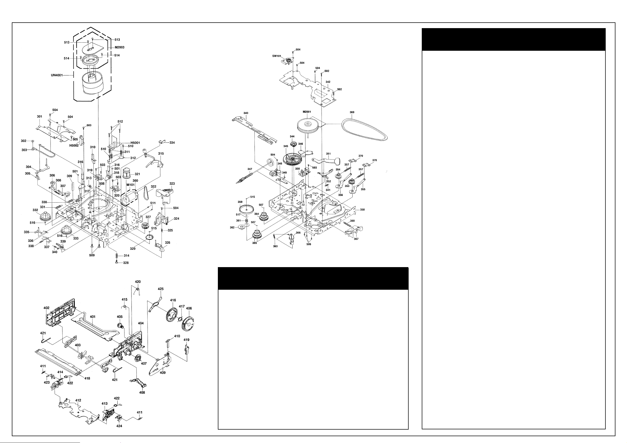
Disassembly Instructions
1-4: LOCATION OF PRINTED CIRCUIT
BOARDS
(Refer to Fig. 1-4)
CAUTION: BEFORE ATTEMPTING TO
REMOVE OR REPAIR ANY PCB, UNPLUG
THE POWER CORD FROM THE AC SOURCE.
Fig. 1-4
1-5: MAIN PCB (Refer to Fig. 1-5)
1. Remove the 5 screws (1).
2. Unlock the 2 supports (2) and remove the TV
Main PCB in the direction of the arrow.
Fig. 1-5
1-6: TOP SHIELD PLATE AND BOTTOM
SHIELD PLATE
(Refer to Fig. 1-6)
1. Remove the 4 screws (1).
2. Remove the Top Shield Plate in the direction
of arrow (A).
3. Remove the screw (2).
4. Remove the Bottom Shield Plate in the
direction of arrow (B).
Fig. 1-6
1-7: FRONT LOADING UNIT 6, CHASSIS
SECTION, JACK PLATE AND VCR MAIN PCB
(Refer to Fig. 1-7-A)
1. Remove the screw (1).
2. Remove the screw (2).
3. Remove the screw (3).
4. Remove the Front Loading Unit 6 in the
direction of arrow (A).
5. Remove the 3 screws (4).
6. Remove the 2 screws (5).
7. Remove the Chassis Section in the direction
of arrow (B).
8. Remove the 2 screws (6).
9. Unlock the 2 supports (7) and remove the
Jack Plate in the direction of arrow (C).
10.Unlock the support (8) and remove the VCR
Main PCB.
NOTE
When installing the Front Loading Unit 6, align
the timing marks and pull the Cassette Holder
Ass’y in the direction of arrow (D). (Refer to Fig.
1-7-B)
Fig. 1-7-A
Fig. 1-7-B
2. REMOVAL OF DECK PARTS
2-1: LINK GEAR (R) / CAM GEAR (Refer to
Fig. 2-1)
1. Unlock the support (1).
2. Remove the BOT Sensor Cover and BOT
Reflector.
3. Unlock the 3 supports (2).
4. Remove the Side Bracket R2 and Spring
Earth.
5. Remove the Flap Lever, Link Gear (R), Cam
Gear Ass’y and BOT Lever.
NOTES
When installing the Link Ass’y 2 and Link Gear
(R), align the timing Marks.
Fig. 2-1
2-2: TOP BRACKET / TAPE PIECE GUIDE
(Refer to Fig. 2-2)
1. Unlock the 2 supports (1).
2. Remove the Tape Piece Guide.
3. Unlock the 4 supports (2).
4. Remove the Top Bracket.
5. Remove the Side Bracket R1 and Side
Bracket L.
6. Unlock the support (3).
7. Remove the Joint Gear.
8. Remove the Bracket R Spring.
Fig. 2-2
2-3: LINK ASS’Y 2 (Refer to Fig. 2-3)
1. After removing in the direction (A) of Link
Ass’y 2, remove the Link Ass’y 2 in the
direction (B).
NOTE
Install the (B) first, then install the (A).
Fig. 2-3
2-4: CASSETTE SIDE R (Refer to Fig. 2-4)
1. Unlock the 2 supports (1).
2. Remove the Cassette Side R.
3. Remove the Pack Spring.
4. Remove the Locker Spring.
5. Unlock support (2).
6. Remove the Locker R.
Fig. 2-4
2-5: CASSETTE SIDE L (Refer to Fig. 2-5)
1. Unlock the 2 supports (1).
2. Remove the Cassette Side L.
3. Remove the Pack Spring.
4. Remove the Locker Spring.
5. Unlock the support (2).
6. Remove the Locker L.
Fig. 2-5
2-6: BRAKE BRACKET (Refer to Fig. 2-6)
1. Remove the Main Brake Spring, S-S Brake
Spring, Joint Arm Spring and T-S Brake
Spring.
2. Remove the 2 screws (1).
3. Remove the screw (2).
4. Remove the Brake Bracket.
5. Remove the Sub Brake S, Sub Brake T, Main
Brake S Ass’y and Main Brake TAss’y.
6. Remove the Joint Arm.
7. Remove the Reflector LED 2.
Fig. 2-6
2-7: TENSION BAND (Refer to Fig. 2-7)
1. Remove the Tension Arm Spring 1.
2. Remove the Tension Arm Spring 2.
3. Remove the Tension Adjust.
4. Remove the Tension Arm Ass’y.
5. Remove the Tension Band Ass’y.
6. Remove the Tension Lever 2 Ass’y.
Continues on next page.
Recommended Safety Parts
Item Part No. Description