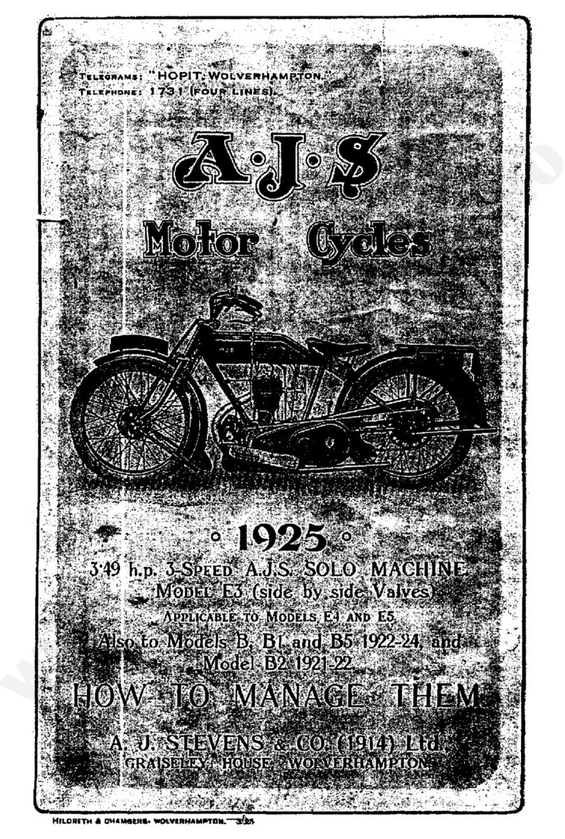
AJS 16M User manual

MAINTENANCE
MANUAL
INSTRUCTION
BOOK
AND
for
1951
350 c.c.
and 500 c.c.
A•J
SPRING FRAME AND RIGID
SINGLE CILINDER MODELS
PRICE 2/6 NETT
A J•S
M O T O R C Y C L E S
Proprietors: ASSOCIATED MOTOR CYCLE LIMITED
PLUMSTEAD • LONDON • S.E.18
EDITION CM-15
•
•S

WHEN CORRESPONDING REGARDING
SERVICE OR SPARES
ALWAYS QUOTE
THE COMPLETE ENGINE NUMBER
(
Including
all letters in it)
Including all letters in it)all letters in it)Including
THIS ENABLES US TO IDENTIFY THE MACHINE
EACH SERIAL OF FRAMES IS NUMBERED FROM ZERO
UPWARDS. THEREFORE THE QUOTATION OF A
FRAME NUMBER ONLY DOES NOT PERMIT A MACHINE
TO BE IDENTIFIED.

MAINTENANCE MANUAL
AND INSTRUCTION BOOK
for
A • J • S
1 9 5 1
SINGLE CYLINDER MOTOR CYCLES
Compiled and Issued by the Manufacturers :
A• J • SMOTOR CYCLES
(Proprietors: ASSOCIATED MOTOR CYCLES LIMITED)
Registered Offices :
PLUMSTEAD ROAD, PLUMSTEAD
LONDON, S.E.18 .. ENGLAND
Nearest Station :
WOOLWICH ARSENAL
(SouthernRegionRailway)
Factories :
BURRAGE GROVE and MAXEY ROAD
PLUMSTEAD, S.E.18
Telegrams and Cables: "ICANHOPIT, WOL-LONDON"
Telephone : WOOlwich 1 22 3 (5 Lines)
Codes : A.B.C. 5th and 6th Edition ; Bentley's; and Private Codes
All correspondence to :—
A• J • S MOTOR CYCLES, PLUMSTEAD ROAD, LONDON, S.E.18
Price : TWO SHILLINGS and
SIXPENCE
EDITION CM-15
A—A

1951 A•J•S MODELS
350 MODEL 16M RIGID FRAME
350 MODEL 16MS SPRING FRAME
350 MODEL 16MC COMPETITION RIGID FRAME
350 MODEL 16MCS COMPETITION SPRING FRAME
500 MODEL 18 RIGID FRAME
500 MODEL 18S SPRING FRAME
500 MODEL 18C COMPETITION RIGID FRAME
500 MODEL 18CS COMPETITION SPRING FRAME
350 — Bore 69 mm. Stroke 93 mm. Capacity 347 c.c.
500 — Bore 82·5 mm. Stroke 93 mm. Capacity 498 c.c.
Motorcycling is one of the most economical and pleasurable modes of
transport. It is our sincere wish that every " A . J . S " owner
should obtain, from his mount, the service, comfort and innumerable miles
of low-cost travel that we have earnestly endeavoured to build into it.
However, it must be remembered that, although a motor cycle is of simple
design and construction, it is, nevertheless, a highly specialised piece of
engineering. In consequence, it must be intelligently and efficiently
maintained in order to provide unfailing reliability.
In this book are non-technical instructions for carrying out all the mainten-
ance operations likely to be called for in strenuous service and illustrations
are provided to assist. Neglect to make essential adjustments, only casual
attention to lubrication and the lack of periodical maintenance attention
will soon neutralise the best efforts of the designers and may bring needless
trouble to the owner.
We are always pleased to give " A . J . S " owners the full benefit
of our wide experience in matters relating to motor cycles of our manu-
facture and elsewhere will be found details of the particulars that should
be given us when making such an enquiry.
A . J . S MOTOR CYCLES
INTRODUCTION
2

1951
RIGID
16M and 18
1951
SPRING
16MS and 18S
1951
RIGID
COMPETITION
16MC and 18C
1951
SPRING
COMPETITION
16MCS and 18CS
3

DATA
Make
A.J.S.
Models 350 c.c. 51/16M
51/16MS
51/16MC
51/16MCS
500 c.c. 51/18
51/18S
51/18C
51/18CS
Identity
Engine Number Scamped on left hand side of crankcase
Frame Number Stamped on seat lug of main frame, on right hand side (below the saddle)
Bore 350 c.c. Models—69 mm. (approx.) (2Fin.)
500 c.c. Models—82·5 mm. (approx.) (34in.)
Number of Cylinders (all models) One
Stroke All Models—93 mm. (approx.) (3·65625 in.)
Engine capacity, in cubic centimetres 350 Models—51/16M, 51/16MS, 51/16MC and 51/16MCS—347
500 Models—51/18, 51/18S, 51/18C and 51/18CS—498
Brake Liners
Length
6sin.
Width
d
in.
Thickness
x
in.
Radius
3½ in.
Quantity off
4 (2 per brake)
Part
number
010440 (3836-2)
Brake liner rivets
Diameter
8
in.
Length
a
in.
Material
Copper
Type
Tubular
Head
Tinmans No. 11
Quantity
per liner
6
Part
number
000113 (STD-113)
Capacities
Location
Engine 350 c.c.
Engine 500 c.c.
Gear box
Front fork (each side)
Rear leg (each leg)*
Rear wheel fork hinge bearing*
Fuel tank (Rigid and Spring frame)
Fuel tank (Competition)
Oil tank
*On Spring Frame Models only.
British
21·170 cub. in.
30·380 cub. in.
1 pint
6½
fl.
ozs.
3 fl. ozs.
1½
fl.
ozs.
3 gallons
2¼gallons
4 pints
Metric
347 c.c.
498 c.c.
568·2 c.c.
184·6 c.c.
85 c.c.
42·6 c.c.
13·638 litres
10·2285 litres
2·275 litres
Carburetter
Type
Main jet size (no air filter fitted)
Main jet size (air filter fitted)
Throttle valve size
Jet taper needle position
350
76AE/IAK
150
130
6/4
3rd notch
from top
500
89B/IAK
180
160
29/4
2nd notch
from top
Chain whip (all models)
Front chain Rear chain Dynamo chain
ain. a*.ni½ot .ni¼
*When no load on the saddle the rear chain whip on Spring Frame Models is 18in.
Magneto chain
¼
in.
… … … … … … … … … … … … …
… … … … … … … … … … …
… … … … … … … …
… … … … … … … …
… …
… … … … … … … … … …
… … … … … … … …
…………………………
… … … … … …
… … … … … …
… … … … … … … …
…………………
… … … … …
… … … … …
… … … … … …
… … … …
… … … …
………
… … … …
… … … … … …
… …
4

Chains
Models
350 Competition
350 Touring
500 Competition
500 Touring
All rigid models (Touring)
All spring models
All competition rigid models
All models
All models
Location
Front driving
Front driving
Front driving
Front driving
Rear driving
Rear driving
Rear driving
Dynamo
Magneto
Pitch
½ in.
½ in.
½ in.
½in.
s
in.
s
in.
s
in.
a
in.
a
in.
Width
·305 in.
·305 in.
·305 in.
·305 in.
·380 in.
·380 in.
·380 in.
·225 in.
·225 in.
Number
of Links
65
66
66
67
94
98
90
49
58
Part
number
110046-65
110046-66
110046-66
110046-67
110056-94
110056-98
110056-90
110038-49
110038-58
DYNAMO AND MAGNETO CHAINS ARE ENDLESS. " NUMBER OF
LINKS " OF FRONT AND REAR DRIVING CHAINS INCLUDE ONE
SPRING CONNECTING LINK PER CHAIN.
Compression ratios
Model
350
500
With no
compression plate
6·35 to 1
7·24 to
With one
compression plate
5·88 to 1
6·00 to 1
Gear box ratios
Standard
Competition (Rigid)
Competition (Spring)
First gear
1 to 2·67
1
to 3·16
1 to 2·67
Second gear
1
to 1·76
1 to 2·09
1
to 1·69
Third gear
1 to 1·28
1 to 1·28
1 to 1·25
Fourth gear (top)
1
to 1
1
to 1
1
to 1
Gear ratios (models 16M-16MS-18-18S)
Engine sprocket size
15 teeth
16 teeth
17 teeth
18 teeth *
19 teeth
20 teeth
21 teeth †
First gear
18·69 to 1
17·5 to 1
16·44 to 1
15·57 to 1
14·6 to 1
14·01 to 1
13·35 to 1
Second gear
12·32 to 1
11·54 to
1
10·84 to 1
10·26 to 1
9·6 to 1
9·24 to 1
8·8 to 1
Third gear
8·96 to 1
8·39 to 1
7·88 to 1
7·47 to 1
7·0 to 1
6·72 to 1
6·4 to 1
Fourth gear
(top)
7 to 1
6·56 to 1
6·16 to
1
5·83 to 1
5·49 to 1
5·25 to 1
5·0 to 1
Part
number
014015
014016
014017
014018
014019
014020
014021
*Standard Solo sprocket for Models 16M and 16MS.
†Standard Solo sprocket for Models 18 and 18S.
Gear ratios (models 16MC-18C)
Engine sprocket size
15 teeth
16 teeth *
17 teeth
18 teeth †
19 teeth
20 teeth
21 teeth
First gear
22·12 to 1
20·72 to 1
19·46 to 1
18·44 to 1
17·34 to 1
16·59 to 1
15·8 to 1
Second gear
14·63 to 1
13·71 to 1
12·87 to 1
12·20 to 1
11·47 to
1
10·97 to 1
10·45 to 1
Third gear
8·96 to 1
8·39 to 1
7·88 to 1
7·47 to 1
7·0 to 1
6·72 to 1
6·4 to 1
Fourth gear
(top)
7 to
1
6·56 to 1
6·16 to
1
5·83 to 1
5·49 to 1
5·25 to 1
5·0 to 1
Part
number
014015
014016
014017
014018
014019
014020
014021
* Standard Solo sprocket for Model 16MC.
† Standard Solo sprocket for Model 18C.
… … …
… … …
… … …
… … …
… … … …
… … … …
… … … …
… …
…
………
………
………
………
………
………
………
………
… …
…
………
………
………
………
………
………
………
5

Gear ratios (models 16MCS and 18CS)
Engine sprocket size
15 teeth
16 teeth *
17 teeth
18 teeth †
19 teeth
20 teeth
21 teeth
First gear
18·69 to 1
17·5 to 1
16·44 to 1
15·57 to 1
14·6 to 1
14·01 to 1
13·35 to 1
Second gear
11·83 to 1
11·08 to
1
10·41 to 1
9·85 to 1
9·27 to 1
8·87 to 1
8·45 to 1
Third gear
8·75 to 1
8·2 to 1
7·7 to 1
7·28 to 1
6·86 to 1
6·56 to 1
6·25 to 1
Fourth gear
(top)
7 to 1
6·56 to 1
6·16 to
1
5·83 to 1
5·49 to 1
5·25 to 1
5.0 to 1
Part
number
014015
014016
014017
014018
014019
014020
014021
* standard Solo sprocket for Model 16MCS.
† standard Solo sprocket for Model 18CS.
Ignition (magneto)
Model
16M-16MS-18
18S
16MC-18C
16MCS-18CS
Make
Lucas
Lucas
Type
N1-4
NR1
Rotation
Anti-clock
Anti-clock
Point gap
·012 in.
·012 in.
Ignition point before top
dead centre (with control
in fully advanced position)
½
in.
(39°)
½
in.
(39°)
Ignition (sparking plug)
Model
All Make
K.L.G. Type
FE80
Thread
14 mm.
Reach
¾ in.
Point gap
·015 to ·018 in.
Lighting (dynamo)
Make
Lucas
Type
E3-N Voltage
6Rotation
Anti-clock Part number
20028-A
Lighting (bulbs)
Location
Head lamp (Pre-focus)
Pilot
Rear lamp
Speedometer
Type
Double filament
Single contact
Single contact
Single contact
Voltage
6
6
6
6
Wattage
30X24
3
3
1·8
Cap
Special
M.B.C.
M.B.C.
M.B.C.
Part
number
312
988
988
53205
Oversize parts
The following are the only " oversize " variations provided for the 350 and 500 c.c. Single Cylinder machines.
Big-end rollers :
·001 in. oversize
Cylinder re-bore :
·020 in. and ·040 in. oversize
Pistons and rings :
·020 in. and ·040 in. oversize
Pistons
Model
350
500
Top of skirt diameter
2·7176 in.
3·2490 in.
Bottom of skirt diameter
2·7180 in.
3·2494 in.
Part number
013504
013505
All above measurements are subject to a toleration limit of + or — ·0005 in.
Piston rings
Piston ring gap—Normal
Permissible maximum
Piston ring clearance in groove
·006 in.
·030 in.
·002 in.
… … … … … … … … … …
… … … … … … … …
… … … … … … … … …
… …
… …
… … …
… … …
… …
… …
… …
… …
… …
…
… …
… … …
… … …
… … …
… … …
… … …
… … …
… … …
6

Spokes (350 and 500 rigid and spring frame models)
Location
Front, left side
Front, right side
Rear, left side
Rear, right side
Type
Butted
Butted
Butted
Butted
Gauge
8 x10
9 x 11
7 x 9
7x 9
Length
underhead
5xin.
88in.
88in.
88in.
Quantity
20
20
20
20
Part
number
011018 (37-X-H51)
011014 (12399)
011012 (39-8-H54)
011012 (39-8-H54)
Spokes (350 and 500 Competition models)
Location
Front, left side
Front, right side
Rear, left side
Rear, right side
Type
Butted
Butted
Butted
Butted
Gauge
8 x 10
9 x 11
6
6
Length
underhead
6¼ in.
9xin.
88in.
88in.
Quantity
20
20
20
20
Part
number
012786
017111 (38-18T-H51)
017097 (36-2-H51)
017097 (36-2-H51)
Sprockets (engine)
Model
16MC
16MCS
16M
16MS
18C
18CS
18
18S
Number
of teeth
16
18
21
Chain
pitch
½ in.
½ in.
½ in.
Chain
width
·305 in.
·305 in.
·305 in.
Part
number
014016
014018
014021
Sprockets
Location
Clutch
Clutch
Gear box
Gear box
Rear wheel
Number
of teeth
40
40
16
16
42
Chain
pitch
½ in.
½ in.
s
in.
s
in.
s
in.
Chain
width
·305 in.
·305 in.
·380 in.
·380 in.
·380 in.
Part
number
7-X-28
G4-2
179-X-7
22BA-14
010293
Models
All except Competition Spring Frame
Competition Spring Frame
All except Competition Spring Frame
Competition Spring Frame
All
Valve timing (with ·016 inch rocker clearance)
INLET VALVE
Opens before top dead centre
Closes after bottom dead centre 32°
63°
EXHAUST VALVE
Opens before bottom dead centre
Closes after top dead centre 65°
30°
Valve timing pinion
Retained by nut, threaded vin. by 26 threads per in. Left hand thread. Part number 000221 (STD-221).
Weight
Weight of machine with empty tanks
Model
350
500
Standard
Rigid frame
344 lbs.
353 lbs.
Spring frame
375 lbs.
386 lbs.
Competition
Rigid frame
300 lbs.
303 lbs.
Wheels (bearing end play)
Bearing end play ·002 in.
… … … …
… … … …
… … … …
… … … …
… …
… …
… …
… …
… … … …
… … … …
… … … …
… … …
… … …
… …
… …
… …
… …
…… …
… … …
… … …
… … …
7

CONTROLS
(1)
(2)
(3)
(4)
(5)
(6)
(7)
(8)
(9)
(10)
(II)
(12)
(13)
(14)
(15)
(16)
(17)
Throttletwistgrip.Onrighthandlebar.Twistinwardstoopen.When
fullyclosedengineshouldjustidlewhenhot.
Airlever.Smallleveronrighthandlebar.Pullinwardstoincreaseairsupply
tocarburetter.Onceset,whenenginehaswarmedup,requiresnoalteration
fordifferentroadspeeds.Shouldbefullyclosedwhenstartingenginefromcold.
Ignitionlever.Smallleveronlefthandlebar.Advancesandretardsignition
point.Pullinwardstoadvanceontouringmodels(retardoncompetitionmodels).
Retardtwo-fifthsoftotalmovementforstarting.
Valvelifterlever.Smallleverclosetoclutchlever.Liftsexhaustvalvefrom
seat,releasingcompressionincombustionchamber,enablingenginetobeeasily
rotatedforstarting.Alsousedforstoppingengineifthrottlestopissetas
advisedabove.
Clutchlever.Largeleveronlefthandlebar.Griptoreleaseclutchsothat
drivetorearwheelisdisconnected.Usedwhenmovingawayfroma standstill
andwhenchanginggear.
Frontbrakelever.Largeleveronrighthandlebar.Griptooperatefront
wheelbrakeand,fornormalbraking,useinconjunctionwithrearbrakeapplication.
Rearbrakelever.Pedalclosetoleftsidefootrest.Depresswithleftfootto
applyrearbrake.Applygentlyanduseincreasingpressureastheroadspeed
decreases.
Gearchangelever.Pedalinhorizontalpositionclosetorightfootrest.Con-
trolsselectionofthefourspeeds,orratios,betweenengineandrearwheel
revolutions,witha " free,"orneutral,position.Seeillustration3.
Kick-starterlever.Verticalpedalonrighthandsideofgearbox.Operated
tostarttheengine.
Lightingswitch.Intopofheadlamp.Controlslampsbya rotatingleverwhich
hasthreepositions:
(1)"OFF"Lampsnoton.
(2)" L " Pilotbulbinheadlampandrearlampandspeedometerlampon.
(3)" H " Headandrearlampandspeedometerlampon.
Ammeter.Intopofheadlamp.Indicatesflowofelectriccurrent,in,orout,
ofbattery.("Charge" or" Discharge.")
Hornswitch.Pressswitchonrighthandlebar.Depressbuttontosoundhorn.
Gearboxfillercap.Locatedontopedgeofkick-startercasecover.Allows
insertionoflubricantandaccesstoclutchinnerwire.
Footrestforrider.Onelocatedeachsideofmachine.
Petroltankfillercap.Locatedintopoffueltank.Torelease,slightlydepress,
turnfullytotheleft,andthenliftaway.Therearetwolockingpositions.The
middleposition,betweenthefullytighteneddownand" liftaway" positions,
isinthenatureofa " safety" devicetopreventlossthatmightbeoccasionedby
unauthorisedmeddling.
Oiltankfillercap.Locatedontopedgeofoiltank.Theconstructionand
operationisexactlyasthepetroltankfillercap.
Dippingswitch.Triggerswitchonlefthandlebar.Usedtoselectnormalor
"dipped" beamof headlampwhenmainlightingswitchleveris in the" H "
position.(Theheadlampbulbhastwofilaments.)
8

Ifanyadjustmentismadetotherearbrakepedalmakecertainthebrakedoesnotbind
andalsoseethereisnotexcessivefreepedalmovementbeforethebrakecomes" on."
Illustration1
ShowingControls
Beforeusingthemachine,sitonthesaddleandbecomefamiliarwiththepositionand
operationofthevariouscontrols.Payparticularattentiontothegearpositions.
B—A
9

DRIVING
FUEL
At the time of publishing this instruction book only one grade of motor fuel (Pool Spirit)
is on sale, but it may be that soon the various grades of pre-war petrol will again be avail-
able when the use of best quality fuel is recommended because the small amount of
economy that might be considered to accrue by using the cheaper grades is more than
offset by the advantages obtained by using only Number One grades.
FUEL SUPPLY
Two fuel feed taps are situated underneath the rear end of the petrol tank. (One each
side.) Both must be shut off when the machine is left standing for more than a few
minutes.
The tap plungers work horizontally. To open, the hexagon knob (marked " push on ")
is pushed towards the body of the tap. To close, press the round milled knob (marked
" push off ").
Normally, only use the tap on the right hand side of the machine and then the other
side will act as a reserve supply. Always re-fuel as soon as possible after being forced
to call upon the reserve, and then, at once, close the " reserve " tap.
It will be noted that, by fitting two petrol feed taps, it is possible to remove the petrol
tank from the machine without the necessity of first draining it of fuel.
Illustration 2
Kick-starter
quadrant and ratchet pinion
10

STARTINGTHEENGINE
(a) Seethatthereissufficientfuelinthepetroltank.
(b) Seethatthereissufficientoilintheoiltank.
(c) Seethatthegearpedalisintheneutralposition.
(d) Pushinwardthehexagonalendofoff-sidepetroltapslide.
(e) Seethattheaircontrolleverisinthefullyclosedposition.
(f) Fullyadvancetheignitionandthenslackbackthecontrollever two-fifthsofits
totalmovement.
(g) Openthethrottlenotmorethanone-sixthofthetotalmovementofthetwistgrip.
(h)Depresstheplungeronthetopofthecarburetterfloatchamberuntilitcanbe
feltthechamberisfullofpetrol.
(i) Raisethevalvelifterlever and,whilekeepingitraised,turnovertheengineseveral
timesbydepressingthekick-starterpedal,threetimes,theobjectbeingtofree
theengine.(Thisonlyappliesiftheengineiscold.)
(j) Depressthekick-starteruntilcompressionisfelt,thenraisethevalvelifterlever
andeasetheenginejustovercompression.Then,afterallowingthekick-starter
pedaltoreturnnearlytoitsnormalposition,giveita longswingingkickwiththe
valveclosedandtheengineshouldimmediatelyfire.
Thekick-startermechanismmustbeallowedtoengageproperlybeforeputtingheavy
pressureonthekick-startercrankpedalpin.Thatmeanstherearetwodefinite
andseparatemovementswhenoperatingthemechanismbydepressingthecrank.
Thefirstisa slowandgentlemovementwhichendswhenitisfeltthequadranthas
engagedwiththeteethontheratchetpinion.(Seeillustration2.)
Illustration3
Showingtherelative
positionstakenupbythe
movinggearindicator
whenthevariousgearsare
engaged.
Themovinggearindicator
isattachedtothecontrol
spindleandthefixedgear
indicatorislocatedonthe
kick-startercasecover.
Thetwoindicatorsare
onlyinlinewitheach
otherwhenthefootgear
changepedalisinthe
neutralposition.
Thefirstslowandgentlemovementisessentialtoavoiddamagetotheteethofthe
kick-starterquadrant.
Aftertheenginehasstarted,slowlyopentheairlever untilitrunsevenly. Thenset
thethrottlesothattheengineisrunningata moderatespeed(neitherracingnorticking
over)andallowtowarmup.Whiledoingthis,checktheoilcirculationasdetailedin
page14.Themachinecanthenbetakenontheroad,
NOTE—Donotraceuptheenginefromcoldanddonotfloodthecarburettertosuch
anextentthatpetrolisdripping,becausethen,intheeventofa backfire,there
isa dangerofsuchloosepetroligniting.Thiscannotpossiblyhappenifthe
startinginstructionsarecarefullyfollowed,but,intheeventofa fire,thereis
nocauseforpanic.Merelyturnoffthepetroltaptoisolatethemainsupply,
openwidethethrottleandturnovertheenginebyoperatingthekick-starter
pedalwhensuctionwillextinguishthefire.
11

STOPPINGTHEENGINE
Tostoptheengine,closethethrottle,raisethevalvelifterleverandkeepitraised
untiltheenginehasceasedtorevolve.
ONTHEROAD
Havingstartedandwarmeduptheengine,takethemachineoffthestand,sitastrideit,
freetheclutchbypullingupthelargelever ontheleftbarandengagethelowestgear.
Next,slowlyreleasetheclutchlever andthemachinewillcommencetomoveforward.
Asitdoesthis,theenginespeedwilltendtodropasitpicksuptheloadsoitwillbe
necessarytoincreaseslightlythethrottleopening,bitbybit,tokeeptheenginespeed
gentlyrising.
Whenwellunderway,disengagetheclutch,slightlyclosethethrottle,engagesecond
gearandreleasetheclutchlever,thenopenupthethrottletoincreasethespeedof
themachine.Repeattheseoperationsinordertoengagethirdandtopgears.
Toengagea highergearthepedalispresseddownwardwiththetoeanda lowergearis
obtainedbyraisingthepedalwiththeinstep.Toengagefirstgearfromtheneutral
position,thepedalisthereforeraised.Aftereachpedalmovement,internalsprings
returnthepedaltoitsnormalhorizontalposition.
Thepedalmustbemovedtothefullextentofitstravelwhenselectinga gear,either
upordown.Itmustnotbe" stampeddown" orjabbed,butfirmlyanddecisively
movedtillitstops.A half-heartedmovementmaynotgivefullengagement.Keep
thefootoffthepedalwhendrivingandbetweeneachgearchangebecause,unlessthe
levercanfreelyreturntoitsnormalcentralposition,thenextgearcannotbeengaged.
Finally,fullyadvancetheignitionandleaveitinthatpositionunlessitisnecessaryto
retardinordertoeasetheengineandsoprevent" pinking" whenpullinghardona
gradient.
STOPPINGTHEMACHINE
Tostopthemachine,closethethrottle,declutchbyliftingthelargeleverontheleft
handlebar,andgentlyapplybothbrakes,increasingthepressureonthemastheroad
speedofthemachinedecreases.Placethegearchangefootpedalintheneutralposition
andstoptheengine.
Beforeleavingthemachine,turnoffthefuelsupply.
IMPORTANTNOTICE
NEVERDRIVEAWAYATHIGHSPEEDWHENSTARTINGA RUNWITHA
COLDENGINE.GIVETHEOILA CHANCETOWARMUPANDTHINOUT,
PARTICULARLYWHENTHEMACHINEISCOLD.UNTILTHEOILREACHES
ITSNORMALRUNNINGTEMPERATURETHECIRCULATIONIS
RESTRICTED.SEIZURESCANBEAVOIDEDBYTAKINGTHISSIMPLE
ESSENTIALPRECAUTION.
RUNNINGIN
Althoughitiscustomarytoquotepermittedmaximumspeedsonthevariousgears
duringtheperiodofrunningin,thesearereallynoguidetooverdriving,theonlyessential
thingtoavoidbeingtheuseoflargethrottleopening.
Iftheprecautionistakenoflimitingtheuseofthethrottletoaboutone-thirdofits
openingduringthefirst1,000miles,irrespectiveoftheroadspeed,andwhetheronthe
levelorclimbing,thenecessaryconditionsforrunninginwillhavebeenobserved.
12

Specialattentionmustbegiven,duringtherunninginperiod,tosuchdetailsasvalve
rockeradjustment,chains,brakes,contactbreakerpoints,andsteeringheadbearings,
allofwhichtendtobeddowninthefirsthundredmilesorso.Particularnotemustbe
madeoftheadjustmentofsteeringheadbearings,which,ifrunina slackcondition,will
bequicklyruined.Afterthisbeddingdownprocesshastakenplace,adjustmentsto
suchdetailswillprobablyonlybenecessaryatlengthyintervals.
Afterabout1,000mileshavebeencoveredlargerthrottleopeningsmaybegradually
indulgedinforshortburstsonly.
Untilatleast2,000mileshavebeencoveredtheownerofa newmachineisstrongly
advisedtocurbhisnaturaldesiretolearnthemount'smaximumcapabilities.Restraint
inthisdirectionwillbeamplyrepaidlater.
NOTESONDRIVING
If,atfirst,thelowestgearwillnotengage,releasetheclutchleverandaftera secondor
two,makeanotherattempt.Thisconditionmayexistina newmachine,butittendsto
disappearaftera littleuse,
Alwaysendeavourtomakethemovementsofhand(ontheclutch)andfoot(onthegear
pedal)assimultaneousaspossible,andremember,inallgearchanges,a steadypressure
ofthefootisdesirable.Thispressureshouldbemaintaineduntiltheclutchisfully
released.Itisnotsufficientjusttojabthefootpedalandthenreleasetheclutchlever.
Whenactuallyinmotion,itwillbefoundsufficienttomerelyfreetheclutcha trifle,
toeasethedrivewhenchanginggearand,withreasonablecare,changesofgearthen
canbemadewithouta sound.
Donotunnecessarilyracetheengineorletintheclutchsufficientlysuddenlytocause
therearwheeltospin.Takea prideinmakinga smoothget-away.
Whenchanginguptoa highergear,astheclutchisfreed,thethrottleshouldbeslightly
closedsothattheenginespeedmaybereducedtokeepinstepwiththehighergearratio.
Conversely,whenchangingdowntoa lowergear,thethrottleshouldberegulatedso
thattheenginespeedisincreasedtokeepinstepwiththelowergearratio.
Donotsliptheclutchtocontroltheroadspeed.
Theclutchmustonlybeusedwhenstartingfroma standstillandwhenchanginggear
ItmustNOTbeoperatedtoeasetheengine,insteadofchanginggear,orbeheldout,
inorderto" free-wheel."
TheexhaustvalvelifterisNOTusedinnormaldrivingonmainandsecondaryroads.
Whentravellingslowly,suchasmayoccurintrafficorona hill,andtheenginecommences
tolabour,itisthennecessarytochangetoa lowergear.Engine" knocking" or
"pinking" anda harshnessinthetransmissionaresymptomsofsuchlabourandalthough
reliefcansometimesbefoundbyretardingtheignition,itisgenerallymuchbetterto
changedown.A gooddriverisabletosensesuchconditionsandwillmakethechange
beforetheenginehasreachedthestageofdistress.Thegearboxisprovidedtobe
usedandconsequentlyfulluseshouldbemadeoftheintermediategearstoobtain
effortlessrunningandsmoothhillclimbing.
Keepthefeetclearofthebrakeandgearpedalswhennotactuallyusingthemandkeep
thehandofftheclutchlever whennotinuse.
Driveasmuchaspossibleonthethrottle,makingtheminimumuseofthebrakes.
Whenusingthemachineonwetorgreasyroads,itisgenerallybettertoapplyBOTH
brakestogether,becausesuddenorharshapplicationofeitherbrakeonly,undersuch
conditions,mayresultina skid.
Inallconditions,itisadvisabletomakea habitofalwaysusingbothbrakestogether
ratherthanhabituallyusingtherearbrakeandreservingthefrontbrakeforemergency.
13

CHECKINGOILCIRCULATION
Provisionismadetoobservetheoilincirculationanditisadvisabletodothisbefore
eachrun.
Ifthefillercapontheoiltankisremovedthebentoverendoftheoilreturnpipewill
benoticedsometwoinchesbelowthelevelofthefillercaporificeandthereturning
oilcanbeseenrunningfromit.ThischeckshouldbemadeImmediatelyafterstarting
theenginefromcold.Thisisbecausewhiletheengineisstationary,oilfromallparts
oftheinterioroftheenginedrainsbackintothecrankcasesump,sothat,untilthissurplus
iscleared,thereturnflowisverypositiveandcontinuous.Therefore,iftheoilcircula-
tionisderanged,thefactisapparentatoncebythelackofa steadyreturnflow.
Illustration4
Showingtheoiltankwiththefelt
filterinitscylindricalhousingand
themetalstrainermountedonthe
entryendofthefeedpipeunion.
Alsoshowsthedirectionofflowof
oilfromtanktoengineandreturn
flowfromenginetotankviathesmall
spout,locatedsothatitcanbe
inspectedbyremovingthetank
fillercap.Anairventpipeislocated
inthebackoftheoiltanktoensure
freedomfromair-locks.
FortheconvenienceofOwners,SPARES
STOCKISTSareappointedformostdistricts.
Tosavedelay,andthedeliverysurcharge,
customersarerecommendedtoapplytotheir
nearestAgentorsparesstockist.
14

LUBRICATION
LUBRICANTSTOUSE
Efficientlubricationisofvitalimportanceanditisfalseeconomytousecheapoilsand
greases.
Werecommendthefollowinglubricantstouseinmachinesofourmake:
FORENGINELUBRICATION
SUMMERWINTER
MobiloilD
Castrol"GrandPrix"
Price'sEnergol60
Essolube"Racer"
TripleShell
(SAE-50)
(SAE-60)
(SAE-60)
(SAE-60)
(SAE-50)
MobiloilA
CastrolXL
Price'sEnergol30
Essolube30
DoubleShell
(SAE-30)
(SAE-30)
(SAE-30)
(SAE-30)
(SAE-30)
FORGEARBOXLUBRICATION
MobiloilD
CastrolGrandPrix
Price'sEnergol60
Essolube50
TripleShell
(SAE-50)
(SAE-60)
(SAE-60)
(SAE-50)
(SAE-50)
FORHUBLUBRICATIONANDALLFRAMEPARTSUSINGGREASE
MobilgreaseNo.2
CastroleaseMedium
Price'sBelmolineC
EssoGrease
ShellRetinaxGreaseC.D.
FORTELEDRAULICFRONTFORKSANDTELEDRAULICREARLEGS
MobiloilArctic
Castrolite
Price'sEnergol20
Essolube20
SingleShell
(SAE-20)
(SAE-20)
(SAE-20)
(SAE-20)
(SAE-20)
FORREARCHAINS
Tallow
WhenbuyingoilsandgreasesitisadvisabletospecifytheBrandaswellasthegrade
and,as an additionalprecaution,to buyonlyin sealedcontainersorfrombrandedcabinets.
15

FILLINGTHEGREASEGUN
Thestandardgreasegunconsistsofa barrelhavinga springloadedendcap,towhich
isfixeda centralsteelpistonintheshapeofa longrod.Thispistonfitsintoa small
cylindermadeinonewiththescrewedtopcap,ontheendofwhichisthecuppednozzle
thatfitsoverthegreasenipples.Inthebarrelofthegun,andslidingonthecentral
pistonrod,isa corkpiston.
ThegreasemustbefilledontheTOPofthecorkpiston.Thegunmaybefilledby
insertingthegreaseinthebarrelofthegunbymeansofa lathorsimilar" spoon."
However,itisbettertoobtainthegreasepackedinthespecialcontainersthatare
supplied,havingloosecollarsinwhichareholessothat,byplacingthebarrelofthegun
overtheholeofthecentralfloatingplateandpressingdownwards,thegunisinstantly
chargedwithgrease.Twistingthegun,and,atthesametime,takingitawayfromthe
floatingplate,leavesthetopofthegunbarrelflushwithgrease,andthenallthatremains
tobedoneistoreplacethescrewedtopcap.
ENGINELUBRICATIONSYSTEM
Thisisbydrysumpsystem.Oilfeeds,bygravity,fromtheoiltanktothepumpinthe
crankcase.Thepumpforcesoiltovariousparts,whichthendrainstothebottomof
crankcasesump.Thepumpthenreturnsoiltothetank.Thisprocessiscontinuous
whiletheengineisrevolving.Thepumpisdesignedtoreturnmoreoiltothetank
thanitcanforceintotheengine.Thereforethecrankcasesumpiskeptclearofexcessoil.
Afeltcartridgefilter,intheoiltank,removesforeignmattercollectedbytheoilinits
passagethroughtheengine.A metalgauzestrainerisfittedtotheoilfeedpipeinthe
oiltanktopreventpiecesoffluff,etc.,whichmayfindtheirwayintothetankwhen
replenishing,fromenteringtheoilpump.(SeeIllustration4.)
Feltfilterandmetalstrainershouldbecleanedinpetroleachtimetheoiltankisdrained.
ENGINEOILPUMP
Thepumphasonlyonemovingpart.Thisistheplungerwhichrevolvesandreciprocates.
Rotationiscausedbythewormgearonthetimingsideflywheelaxle.Reciprocation
Itcausedbytheguidepinwhichengagesintheprofiledgroovecutontheplunger.
Oilisfedtothepumpthroughthelowerofthetwooilpipesbetweentankandcrank-
caseandIsreturnedthroughtheupperpipe.
If,foranyreason,thecrankcasehalvesareseparated,theoilpumpplungermust
beremovedfromitshousingbeforeattemptingtoseparatethecrankcase
helves.
ENGINEOILCIRCULATION
Theoilpumpforcesoilthrough:—
(a) A passagecutthroughthetimingsideflywheelaxle,timingsideflywheelandcrank
pintolubricatethebig-endbearing.Thesplashpassestointeriorofcylinder,to
lubricatethecylinderandpiston,andthenfallsintothecrankcasesump.
(b)A passageincrankcase,controlledbyballvalve,directtothecylinder,toassistin
cylinderandpistonlubricationandthenfallsintothecrankcasesump.
(c) A passageintiminggearcasewhereit" buildsup" toa predeterminedlevelto
lubricatethetiminggearsandthenfallsintothecrankcasesump.
(d) Througha pipefromthefrontofoilpumphousingtotherockerboxbywhich
allrockergearandvalvestemsarelubricatedandthenfallsthroughthepushrod
covertubesandtappetguidestothetiminggearcaseand,fromthere,drainsinto
thecrankcasesump,asdetailedinPara.(c).
Theoilpumpextractsoilinthecrankcasesumpandreturnsittooiltank.Onitsway
Itpassesthroughthefeltcartridgefilterlocatedintheoiltank.
16

Illustration5
EngineOilCirculation
THEOILTANKANDFILTERS
Thelevelofoilinthesupplytankshouldneverbeallowedtofallbelowthelowlevel
markand,uponreplenishment,shouldnotbehigherthanoneinchfromthefillercap
orifice,otherwise,whenstartingtheengine,thebulkofoilinthecrankcasesumpmaybe
greaterthanthespaceavailableinthetank.
Theoilfilterismadeincylindricalformofthickfeltandissupportedbya tubularwire
cage.Thefeltisnotdetachablefromthecage.
C—A
17

Ametalgauzestrainer(securedtothefeedpipeunion)standsintheoiltank.
Afterthefirst500miles,againat1,000miles,andsubsequentlyat5,000mileintervals,
itisrecommendedthattheoiltankisdrained,theoilfilterscleanedinpetrolandthe
tankreplenishedwithnewoil.
Foraccesstooilfilter:—
Unscrewthehexagonalheadedcapontopofoiltankandwithdrawthedishedwasher
andspring.Theninserta fingerinthefeltfilterandgentlyraisesameuntilthe
topendtouchestheunderneathofsaddle.Thenbyencirclingthefilterwiththehandit
willbefoundpossibletoexertsufficientupwardpressureontheflexiblesaddletopto
permitthefiltertobecompletelywithdrawnwithoutdistortion.Careisneededto
avoidkinkingthefilter.
Tore-fitfilter:—
Reverseaboveinstructions.
NOTE—If,afterthefilterhasbeenremovedfromthetank,itisdamaged,sothatthe
feltisperforated,ortheendsdistorted,itisessentialtodiscarditandtofita
newfilter.
Becarefultoavoiddamagingthefilterorthecorkwasherunderthehexagonal
cap.
Foraccesstometalstrainer(afteroilhasbeendrainedfromtank):—
Removeoilfeedpipefromunionscrewedintobottomofoiltank.Thisispipenearer
torearwheelandisremovedbyunscrewingitsunionnut.
Springawaypipefromunion.
Unscrewunionfrombottomofoiltank.Metalstrainerisintegralpartofthisunion.
Tore-fitmetalstrainer:—
Reverseaboveinstructions.
ADJUSTMENTOFOILFEED
Theinternalflowofoilisregulatedbyfixedrestrictions.Noadjustmentisprovided
exceptfortheoilfeedtotheinletvalvestem.Thisadjustmentismadebya needle
pointedscrewlocatedintherightsideofcylinderhead.(SeeIllustration6.).Itis
lockedinpositionbya nut.Theapproximatecorrectsettingisone-sixthofa complete
turnfromthefullyclosedposition.Oncesetitrequireslittle,orno,adjustment.
Inletvalvesqueakindicatestheoilfeedadjustmentisnotopenenough.Excessiveoil
consumption,a smokyexhaustoranoiledsparkingplug,generallyindicatestheoil
feedadjustmentisopentoomuch.
EXHAUSTVALVESTEMLUBRICATION
Theexhaustvalvestemislubricatedbyoilfedthrougha passagedrilledinthecylinder
head.Noadjustmentisprovided.Allexcessoilisby-passedbacktothetiminggear
case.
LUBRICATIONPOINTSTOREMEMBER
Adirty,orchoked,feltoilfiltercausesheavyoilconsumption.Thisisbecausethe
returnflowofoiltotheoiltankisslowed,orevenalmostcompletelystopped,thereby
allowinganexcessofoilto" buildup" inthecrankcasesump,muchofwhichpasses
tothepiston.
Acloggedmetalstrainer,inthegravityfeedpipe,willalsocauseimproper,orno,oil
circulation.Thiscanonlyoccurastheresultofaddingdirtyoilwhenreplenishingthe
tank.
Bothendcapsonpumpplungerhousingmustbeair-tight.
Checkoilcirculationbeforestartingeachrun.
18
This manual suits for next models
7
Table of contents
Other AJS Motorcycle manuals